If you need assistance, please send an email to forum at 4hv dot org. To ensure your email is not marked as spam, please include the phrase "4hv help" in the subject line. You can also find assistance via IRC, at irc.shadowworld.net, room #hvcomm.
Support 4hv.org!
Donate:
4hv.org is hosted on a dedicated server. Unfortunately, this server costs and we rely on the help of site members to keep 4hv.org running. Please consider donating. We will place your name on the thanks list and you'll be helping to keep 4hv.org alive and free for everyone. Members whose names appear in red bold have donated recently. Green bold denotes those who have recently donated to keep the server carbon neutral.
Special Thanks To:
Aaron Holmes
Aaron Wheeler
Adam Horden
Alan Scrimgeour
Andre
Andrew Haynes
Anonymous000
asabase
Austin Weil
barney
Barry
Bert Hickman
Bill Kukowski
Blitzorn
Brandon Paradelas
Bruce Bowling
BubeeMike
Byong Park
Cesiumsponge
Chris F.
Chris Hooper
Corey Worthington
Derek Woodroffe
Dalus
Dan Strother
Daniel Davis
Daniel Uhrenholt
datasheetarchive
Dave Billington
Dave Marshall
David F.
Dennis Rogers
drelectrix
Dr. John Gudenas
Dr. Spark
E.TexasTesla
eastvoltresearch
Eirik Taylor
Erik Dyakov
Erlend^SE
Finn Hammer
Firebug24k
GalliumMan
Gary Peterson
George Slade
GhostNull
Gordon Mcknight
Graham Armitage
Grant
GreySoul
Henry H
IamSmooth
In memory of Leo Powning
Jacob Cash
James Howells
James Pawson
Jeff Greenfield
Jeff Thomas
Jesse Frost
Jim Mitchell
jlr134
Joe Mastroianni
John Forcina
John Oberg
John Willcutt
Jon Newcomb
klugesmith
Leslie Wright
Lutz Hoffman
Mads Barnkob
Martin King
Mats Karlsson
Matt Gibson
Matthew Guidry
mbd
Michael D'Angelo
Mikkel
mileswaldron
mister_rf
Neil Foster
Nick de Smith
Nick Soroka
nicklenorp
Nik
Norman Stanley
Patrick Coleman
Paul Brodie
Paul Jordan
Paul Montgomery
Ped
Peter Krogen
Peter Terren
PhilGood
Richard Feldman
Robert Bush
Royce Bailey
Scott Fusare
Scott Newman
smiffy
Stella
Steven Busic
Steve Conner
Steve Jones
Steve Ward
Sulaiman
Thomas Coyle
Thomas A. Wallace
Thomas W
Timo
Torch
Ulf Jonsson
vasil
Vaxian
vladi mazzilli
wastehl
Weston
William Kim
William N.
William Stehl
Wesley Venis
The aforementioned have contributed financially to the continuing triumph of 4hv.org. They are deserving of my most heartfelt thanks.
Registered Member #152
Joined: Sun Feb 12 2006, 03:36PM
Location: Czech Rep.
Posts: 3384
Udo, the output is just 150V, at one instant positive, at the other negative. The output voltage from a full bridge is the same as DC link voltage, with a half bridge it is half.
zzz_julian_zzz: Looks ok to me, except for the current burst at the beginning. That might jump start the arc instead of growing it slowly. I don't think it explains large primary currents but possibly not so straight and long arcs. Possibly the bus voltage is too high, when you turn the interrupter on.
Dr. Dark Current: Ok, you're thinking of a single +150V DC supply and I was thinking about a dual one, i.e. +150V and -150V.
Registered Member #195
Joined: Fri Feb 17 2006, 08:27PM
Location: Berkeley, ca.
Posts: 1111
Hi Julian nice wave form. if you are using a half wave doubler from the line and your reference connection is the center of the caps it will never be more than 150v but you could play games like connecting it to a boost transformer or connect it to 220. I herd Steve Ward say that the power factor is better with full wave rectification with filter caps.
It has been several months since I worked on my QCW.
Started to get busy with other things and new projects, including getting sidetracked on a pair of reasonably sized DRSSTCS (see project here , but I thought it was time to continue tinkering on the small QCW. Since then I've had a few ideas I wanted to try out while still keeping the coil the same. I finally got around to start putting things together.
This revision (I'm calling it v1.5) includes a fancy Bluetooth controller. I did it mostly for fun since I thought it was a bit gimmicky, but it turned out to be very useful indeed! So I can now use my phone to control the coil from a safe distance and not have to carry around a controller anymore. Also, I've upgraded the bus modulator to using a brick IGBT, and I've lowered the resonant frequency by 100kHz (but still using a 6" secondary), so it now oscillates around 360kHz on the upper pole.
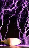
Here's a very early test of the coil in action. I've got the ramp going to just over 200V for about 10ms and it's making around 4+ feet of spark to air. In this test the coil resonates at 360kHz to 340kHz with the buck switching frequency of around 8.5 to 20kHz. Each pulse here is just about 75J.
Here's a video of the coil in action together with the temporary setup!
One thing I noticed with this setup compared to my v1.0 was that the sparks were more knarly. This could also be due to the lower switching frequency where higher frequencies seem to produce straighter sparks; also my toroid is pretty small (8x2") - a bigger one might be better in directing sparks.
Right now have a few ideas in continuing to push the coil to make straighter sparks. For example, a bigger toroid, a higher impedance primary or one with higher coupling, as well as perhaps faster buck switching for a smoother ramp (which may be causing the sparks to break up) and a longer ramp duration.
The next step is of course, to step up the voltage! More to come soon and would appreciate any comments and suggestions!
great development! The bluetooth interface made this coil astoundingly controllable 😄 is the signal all the same? In terms of magnitude and length?
I emailed you on your gmail, waiting for your response. 😄
Right now I'm running just about a 10ms pulse with a ramp peak of about 200V. I didn't receive a mail from you though, are you sure you sent it to the right place?
There's still a bunch of tidying up I need to do - the wires are all over the place and are quite messy, so I'll be tidying it up. Next step is to do some tuning to see what I can get out of this coil
I thought I’d continue to update with some new results from the small QCW project. As always, been trying new things as I figure out what works. I’ve also since made a simple box case for the coil so I can move everything around easily, and have also been experimenting new ‘FAT TOROID’ for the coil .
After discussing with uspring and many other more experienced coilers than I am, I had a few new ideas to try out with the coil. Based on the measured results from the coil so far, it seems that my first few setups had a poor impedance match resulting in less than ideal power transfer. Consequently I had relatively high current in my primary circuit. Two main issues which seem to affect this the most are arc loading and coupling. With my small toroid, heavy arc loading caused significant detuning of my secondary circuit, which decreased Qpri leading to a lower effective load on the inverter side. There are other ways to achieve a similar effect, e.g. increasing primary impedance. However, I wanted to use the same MMC I had and I was running out of turns on my primary coil, so I made a new resonator setup. To summarize, I there exists an ideal effective impedance which the coil should be set to limit the maximum current just below the OCD limit at the peak of the ramp.
The new “Fat Toroid†setup uses my original 5.5†secondary with the new toroid made out of 3†aluminum ducting (it’s actually closer to 3.4†in diameter though). This gave me a resonant frequency of around 330kHz. I also made a new higher coupling primary with a k around 0.39, and tapped such that the coil has an upper pole around 420kHz. With a maximum of 400V on my bus (limited by my variac and my 400V bus cap), I designed the setup to run with a ~300++V peak ramp to hit a 150A limit. This paid off with just over 5 feet of spark (measured around 11.5x secondary length), at a ~310V peak at around 150+A as designed.
Registered Member #3964
Joined: Thu Jun 23 2011, 03:23AM
Location: Valenzuela City
Posts: 332
loneoceans wrote ...
I thought I’d continue to update with some new results from the small QCW project. As always, been trying new things as I figure out what works. I’ve also since made a simple box case for the coil so I can move everything around easily, and have also been experimenting new ‘FAT TOROID’ for the coil .
After discussing with uspring and many other more experienced coilers than I am, I had a few new ideas to try out with the coil. Based on the measured results from the coil so far, it seems that my first few setups had a poor impedance match resulting in less than ideal power transfer. Consequently I had relatively high current in my primary circuit. Two main issues which seem to affect this the most are arc loading and coupling. With my small toroid, heavy arc loading caused significant detuning of my secondary circuit, which decreased Qpri leading to a lower effective load on the inverter side. There are other ways to achieve a similar effect, e.g. increasing primary impedance. However, I wanted to use the same MMC I had and I was running out of turns on my primary coil, so I made a new resonator setup. To summarize, I there exists an ideal effective impedance which the coil should be set to limit the maximum current just below the OCD limit at the peak of the ramp.
The new “Fat Toroid†setup uses my original 5.5†secondary with the new toroid made out of 3†aluminum ducting (it’s actually closer to 3.4†in diameter though). This gave me a resonant frequency of around 330kHz. I also made a new higher coupling primary with a k around 0.39, and tapped such that the coil has an upper pole around 420kHz. With a maximum of 400V on my bus (limited by my variac and my 400V bus cap), I designed the setup to run with a ~300++V peak ramp to hit a 150A limit. This paid off with just over 5 feet of spark (measured around 11.5x secondary length), at a ~310V peak at around 150+A as designed.
HOLY COW! this is impressive ! :D nice work! could you share your way on how to measure impedance (Pri-Sec) and how to match them properly ? :)
This site is powered by e107, which is released under the GNU GPL License. All work on this site, except where otherwise noted, is licensed under a Creative Commons Attribution-ShareAlike 2.5 License. By submitting any information to this site, you agree that anything submitted will be so licensed. Please read our Disclaimer and Policies page for information on your rights and responsibilities regarding this site.


 Small QCW