If you need assistance, please send an email to forum at 4hv dot org. To ensure your email is not marked as spam, please include the phrase "4hv help" in the subject line. You can also find assistance via IRC, at irc.shadowworld.net, room #hvcomm.
Support 4hv.org!
Donate:
4hv.org is hosted on a dedicated server. Unfortunately, this server costs and we rely on the help of site members to keep 4hv.org running. Please consider donating. We will place your name on the thanks list and you'll be helping to keep 4hv.org alive and free for everyone. Members whose names appear in red bold have donated recently. Green bold denotes those who have recently donated to keep the server carbon neutral.
Special Thanks To:
Aaron Holmes
Aaron Wheeler
Adam Horden
Alan Scrimgeour
Andre
Andrew Haynes
Anonymous000
asabase
Austin Weil
barney
Barry
Bert Hickman
Bill Kukowski
Blitzorn
Brandon Paradelas
Bruce Bowling
BubeeMike
Byong Park
Cesiumsponge
Chris F.
Chris Hooper
Corey Worthington
Derek Woodroffe
Dalus
Dan Strother
Daniel Davis
Daniel Uhrenholt
datasheetarchive
Dave Billington
Dave Marshall
David F.
Dennis Rogers
drelectrix
Dr. John Gudenas
Dr. Spark
E.TexasTesla
eastvoltresearch
Eirik Taylor
Erik Dyakov
Erlend^SE
Finn Hammer
Firebug24k
GalliumMan
Gary Peterson
George Slade
GhostNull
Gordon Mcknight
Graham Armitage
Grant
GreySoul
Henry H
IamSmooth
In memory of Leo Powning
Jacob Cash
James Howells
James Pawson
Jeff Greenfield
Jeff Thomas
Jesse Frost
Jim Mitchell
jlr134
Joe Mastroianni
John Forcina
John Oberg
John Willcutt
Jon Newcomb
klugesmith
Leslie Wright
Lutz Hoffman
Mads Barnkob
Martin King
Mats Karlsson
Matt Gibson
Matthew Guidry
mbd
Michael D'Angelo
Mikkel
mileswaldron
mister_rf
Neil Foster
Nick de Smith
Nick Soroka
nicklenorp
Nik
Norman Stanley
Patrick Coleman
Paul Brodie
Paul Jordan
Paul Montgomery
Ped
Peter Krogen
Peter Terren
PhilGood
Richard Feldman
Robert Bush
Royce Bailey
Scott Fusare
Scott Newman
smiffy
Stella
Steven Busic
Steve Conner
Steve Jones
Steve Ward
Sulaiman
Thomas Coyle
Thomas A. Wallace
Thomas W
Timo
Torch
Ulf Jonsson
vasil
Vaxian
vladi mazzilli
wastehl
Weston
William Kim
William N.
William Stehl
Wesley Venis
The aforementioned have contributed financially to the continuing triumph of 4hv.org. They are deserving of my most heartfelt thanks.
Hi loneoceans, the pictures Are not showing up on your thread can you try again. I am building QCW to and I am always looking for ideas. thanks
The photos are uploaded on flickr and I think they do seem to be having some issues (I get the ocassional image which doesn't load). Maybe wait a bit and try again?
Graham Armitage wrote ...
This is impressive. Never tried a QCW coil, but this is inspiring me. Thanks for sharing. You do some awesome work - neat construction. As always your photos are incredible too. Any video of it in operation?
Thanks. I'll go record some short clips and post them up soon!
Dr. Dark Current wrote ...
So are you running on the upper or lower pole?
I haven't really played around with anything but it's running at the upper pole at the moment starting around 465kHz and dropping to 430kHz at the end of the pulse. Both the secondary and primary are about 400kHz independently of each other. Definitely more investigation to follow here. I was also thinking of making a slightly lower frequency secondary, closer to 350khz or so. I suspect this might also help in reducing side-spark breakouts. I could run it in the lower pole by setting the primary to be lower frequency (this is just a normal feedback drivier so it automatically nudges itself to the upper or lower pole), but my reasonaing was that by running it on the upper pole, the spark will drop the frequency causing the coil to become more and more in tune as the spark grows, as opposed to the other case where it would become out of tune as the spark grows. This isn't the case with a normal DRSSTC because they do not have such high coupling. Ideally I'd like to run the coil at the upper pole but tune the primary lower freq than the secondary.
Mads Barnkob wrote ...
Good results. While you think you are late for the QCW party, you are wrong, it would rather seem that you is the first to do a full documentation on your work and from the look of your boards you also have a simpler setup than the first experimental and developing versions we saw from other members :) Could you please post some more photos of the rest of the setup, like the buck converter bridge, primary coil and capacitor etc
Thanks! Been a bit busy these few days but I'll continue to post more. I tried to make the setup as simple as I could, and I'm glad to see it working out.
Here's an overview of the current setup. The only change I made so far is replacing the two bus caps (which were in series) to a single one. I was originally using them as a doubler but it was not enough capacitance, so I replaced it with a single cap with FWR input. Other things visible include my red UD2.7, my 12.8nF capacitor, as well as the buck converter on a grey plastic board. Also visible is the signal transformer for the electronics, the buck inductor and capacitor. Controller is the fiber optic controller by an ATtiny45 in a metal box at the bottom right. Probably not as tidy as a phase-shifted bridge, but I think a bus modulator is more versatile and easier to scale up. I'm not sure how happy my TO247 IGBTs are being hard switched in the buck so I'll push them to see if they can handle it! The bridge should be good to 300A I think, so my buck is probably the limiting factor at the moment.
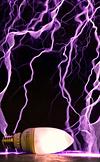
Here's another photo at 150V ramp but in square format :) More to come soon!
Registered Member #3414
Joined: Sun Nov 14 2010, 05:05PM
Location: UK
Posts: 4245
Following on from Mads' comments above, regarding QCW 'documentation', could someone (loneoceans, maybe?) post a 'waveform' of Quasi-Continuous Wave operation, please?
Following on from Mads' comments above, regarding QCW 'documentation', could someone (loneoceans, maybe?) post a 'waveform' of Quasi-Continuous Wave operation, please?
I have a waveform capture of a single ~7ms ramp from 30V to about 150V with a peak current of just about 120A.
Above shows a capture of the primary current in yellow and the buck (blue) output into the inverter in a single shot. Here you can see the interrupter pulse about 7.8ms long (probably a bit too long at the end after it ramps down, so I'll fix my interrupter code soon). In this particular pulse, the current goes up to about 126A just below my current OCD limit. The bus floats at about 30V. Note how at the end of the ramp (where the primary current is about 30A), when the interrupter cuts, the current in the inductor causes the jump in the bus voltage (remember this is an async buck), which then decays through my 4.7k bleeder resistor across my output cap. This has a 3RC value of 406ms, which is sufficient for the low BPS I am currently running at. I plan to improve the bleeder circuit for cleaning up the spike (or simply dropping the ramp to 0 before going up to 30V again, or a small transistor to discharge the filter cap after each pulse).
Another note - I was never really sure what sort of load a high-Z tesla coil would be. The trace above of the primary current may provide some insight. I realized that the envelop looked very much quadratic, and sure enough, I fitted a quadratic line to it and it looks almost perfect (pink line). Now with normal resonance at a fixed bus input, I noticed that the current rises basically linearly. Since the voltage in the primary tank goes up linearly, this implies the load should be constant. With the voltage now increasing from our buck converter, we can think of the voltage increase as a sum of an arithmetic series, which is quadratic (n^2+n /2), again suggesting that the load (tesla coil) is somewhat constant like a resistor. Not sure if this makes sense. This implies that an open-loop control might just work for an even simpler design.
Dr. Dark Current wrote ...
quasi-continuous wave... its a somewhat misleading name, I would call it "ramped SSTC"
Indeed QCW is somewhat of a misnomer I guess. It's interesting to compare it with what I got for my Ramped SSTC 3 (or 'fake QCW!'). See my thread for that coil here:
The way I see how a 'QCW DRSSTC' is different from a ramped SSTC is that the QCW is simply a ramped SSTC employing a resonant capacitor which allows for much greater primary current. An easy way is to think of it canceling the impedance of the primary coil.
This little coil made about foot long sparks with about 3.5ms ramp about 30A peak in sync with 208V mains (it's just a normal half bridge SSTC), so it really is kind of like a baby QCW I guess. But much of the fun in a QCW is getting the buck converter (or your phase shift) working! This also allows for longer ramps and more fun in making your own ramp profiles.
Registered Member #3964
Joined: Thu Jun 23 2011, 03:23AM
Location: Valenzuela City
Posts: 332
Nice work there my friend ! good results indeed. I'm currently building my QCWDRSSTC too at the moment and having similar results with yours :) sooner i'll be posting my results too :) the only difference I think is that I don't have plan on selling anything heheh :) again nice QCW coil!
This site is powered by e107, which is released under the GNU GPL License. All work on this site, except where otherwise noted, is licensed under a Creative Commons Attribution-ShareAlike 2.5 License. By submitting any information to this site, you agree that anything submitted will be so licensed. Please read our Disclaimer and Policies page for information on your rights and responsibilities regarding this site.


 Small QCW


 As others have said, you will be the first to actually document a QCW build.


