If you need assistance, please send an email to forum at 4hv dot org. To ensure your email is not marked as spam, please include the phrase "4hv help" in the subject line. You can also find assistance via IRC, at irc.shadowworld.net, room #hvcomm.
Support 4hv.org!
Donate:
4hv.org is hosted on a dedicated server. Unfortunately, this server costs and we rely on the help of site members to keep 4hv.org running. Please consider donating. We will place your name on the thanks list and you'll be helping to keep 4hv.org alive and free for everyone. Members whose names appear in red bold have donated recently. Green bold denotes those who have recently donated to keep the server carbon neutral.
Special Thanks To:
Aaron Holmes
Aaron Wheeler
Adam Horden
Alan Scrimgeour
Andre
Andrew Haynes
Anonymous000
asabase
Austin Weil
barney
Barry
Bert Hickman
Bill Kukowski
Blitzorn
Brandon Paradelas
Bruce Bowling
BubeeMike
Byong Park
Cesiumsponge
Chris F.
Chris Hooper
Corey Worthington
Derek Woodroffe
Dalus
Dan Strother
Daniel Davis
Daniel Uhrenholt
datasheetarchive
Dave Billington
Dave Marshall
David F.
Dennis Rogers
drelectrix
Dr. John Gudenas
Dr. Spark
E.TexasTesla
eastvoltresearch
Eirik Taylor
Erik Dyakov
Erlend^SE
Finn Hammer
Firebug24k
GalliumMan
Gary Peterson
George Slade
GhostNull
Gordon Mcknight
Graham Armitage
Grant
GreySoul
Henry H
IamSmooth
In memory of Leo Powning
Jacob Cash
James Howells
James Pawson
Jeff Greenfield
Jeff Thomas
Jesse Frost
Jim Mitchell
jlr134
Joe Mastroianni
John Forcina
John Oberg
John Willcutt
Jon Newcomb
klugesmith
Leslie Wright
Lutz Hoffman
Mads Barnkob
Martin King
Mats Karlsson
Matt Gibson
Matthew Guidry
mbd
Michael D'Angelo
Mikkel
mileswaldron
mister_rf
Neil Foster
Nick de Smith
Nick Soroka
nicklenorp
Nik
Norman Stanley
Patrick Coleman
Paul Brodie
Paul Jordan
Paul Montgomery
Ped
Peter Krogen
Peter Terren
PhilGood
Richard Feldman
Robert Bush
Royce Bailey
Scott Fusare
Scott Newman
smiffy
Stella
Steven Busic
Steve Conner
Steve Jones
Steve Ward
Sulaiman
Thomas Coyle
Thomas A. Wallace
Thomas W
Timo
Torch
Ulf Jonsson
vasil
Vaxian
vladi mazzilli
wastehl
Weston
William Kim
William N.
William Stehl
Wesley Venis
The aforementioned have contributed financially to the continuing triumph of 4hv.org. They are deserving of my most heartfelt thanks.
Eric, I think you somehow added input and output power instead of subtracting them. Also, you should run your simulation longer. At the end of the burst you will see, that there are positive and negative components to the difference, which will on the average be zero. Initially there is a difference between input and output power due the charging up of the tanks. Once they have gotten to their final value, the difference will on the average go to zero. In BSVis coil, the amount of energy in the primary and secondary tank is small compared to the total bang energy, so most of the time input and out power should be equal. That is, of course, only so if there aren't copper losses in the primary.
EDIT:
Here is what I’m doing. I measure the L , C, and R values of the secondary using a high frequency LCR bridge at resonance. (Calculated values would also work) This gives me the base resonant frequency of the secondary with no spark loading. Then what I do is look at the frequency/phase shift of the secondary (via a base current CT) with various lengths of spark loading down the secondary.
Interesting stuff, do you measure the phase shift between primary and secondary current?
Registered Member #1637
Joined: Sat Aug 16 2008, 04:47AM
Location: Kiev, Ukraine
Posts: 83
BSVi, would you be interested in doing a measurement of frequency/phase shit for various lengths of sparks on your system? In addition provide your secondary parameters? I would be interested to do a comparison.
I can measure both freq and phase (as i suspect, of secondary current, relatively to what?), but I dont have high-speed camera to compare results to spark length.
do you try to sync the phasing to the ring up in the primary
I don't understand what are you mean by "ring up in the primary". If the question is "do I synchronize phase shift to primary current", then yes, I do. It's also questionable why some streamers are much smaller than others. I suspect it's some glitch in control circutry or, maybe, good streamers happens on the peak of line voltage.
Question, should the energy lead
I have tried different ramp profiles (I suspect that is what you mean by "lead"), and results are pretty obvious - if you raise equalent voltege too fast, streamer explodes into branches. Linear ramp works best.
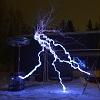
I just wanted to tell you this is one awesome great super-coil!!!
Thank you!
Want proof?
Outstanding!
By the way, guys. Due to war in the Ukraine, I'm looking for a job abroad. If your company needs full-stack electronics engeneer and consider foreigner, feel free to contact me via PM. I'm 28 y/o and mainly do MCU programming, but I'm also good at hardware design, pcb layout, FPGA and PC programming.
Registered Member #195
Joined: Fri Feb 17 2006, 08:27PM
Location: Berkeley, ca.
Posts: 1111
BSVI do you use a FPGA to control the bridge half's and do you have pictures of the driver and its controller. thanks for the reply I would like to build my own QCW I haven't decided whether to phase shift the bridges or use a ramp generator and there advantages.
I live near silicon valley and I would think that there would be a big demand for your skills hear in California. How far do you want to go? Europe or the US. Has any of the fighting affected life in Kiev
Registered Member #1637
Joined: Sat Aug 16 2008, 04:47AM
Location: Kiev, Ukraine
Posts: 83
BSVI do you use a FPGA to control the bridge half's and do you have pictures of the driver and its controller.
No, I'v decided to move away from FPGAs for this project. You can do a lot of cool things with them, but for hobby use it takes too long to write code/testbenches. Now I'm a little sorry for this decision, because phase shifting requires corrections that you can't do in analog without lots of excess circutry. For example, I think it would be better to adjust QCW ramp for transient frequency. I have pretty much all FPGA code to redo this project with it, but I see no sense.
In this project I'm using xc9572 with analog comparator to do phase shifting. One input of comparator is driven with current source+capacitor to make linear ramp. This current source is reset on feedback edges to synchronize with feedback. Other comparator's input is feed with filtered PWM. In this way comprator changes it's output with phase shift from feedback and this shift is determined by PWM value.
I'v ordered 10 boards from china. When they arrive, I'll sell them for all who interested. Those board should be able to drive regular DRSSTC as well. I also have to write documentation. Hate to write documentation :(
Current setup looks as messy as this:
How far do you want to go?
Ideally, I want to go somewere near - Poland or Czech Republic as an example, but really, you dont think much when enemy is at your borders. Also, the only foreign language I know is english. As I know, it's hard to get US visa, for those who havent travelled alot so I didnt think about US. Anyway, to move I need some kind of job offer with relocation sponsorship. I can't do it myself.
Has any of the fighting affected life in Kiev
There is no actual fighting in Kiev, but economical effects affects life and expectations are really bad. I can tell all the uplesanties in separate thread or via PM if you wish.
Registered Member #599
Joined: Thu Mar 22 2007, 07:40PM
Location: Northern Finland, Rovaniemi
Posts: 624
BSVi wrote ...
BSVI do you use a FPGA to control the bridge half's and do you have pictures of the driver and its controller.
No, I'v decided to move away from FPGAs for this project. You can do a lot of cool things with them, but for hobby use it takes too long to write code/testbenches. Now I'm a little sorry for this decision, because phase shifting requires corrections that you can't do in analog without lots of excess circutry. For example, I think it would be better to adjust QCW ramp for transient frequency. I have pretty much all FPGA code to redo this project with it, but I see no sense.
In this project I'm using xc9572 with analog comparator to do phase shifting. One input of comparator is driven with current source+capacitor to make linear ramp. This current source is reset on feedback edges to synchronize with feedback. Other comparator's input is feed with filtered PWM. In this way comprator changes it's output with phase shift from feedback and this shift is determined by PWM value.
I'v ordered 10 boards from china. When they arrive, I'll sell them for all who interested. Those board should be able to drive regular DRSSTC as well. I also have to write documentation. Hate to write documentation :(
Registered Member #2292
Joined: Fri Aug 14 2009, 05:33PM
Location: The Wild West AKA Arizona
Posts: 795
Steve,
What you said agrees with my simulation. Stored reactive energy in the primary circuit = higher losses. Lowering coupling makes these losses higher, because the energy stays sloshing in the primary circuit longer.
Also I didn’t neglect either resistance in the simulation; both are included as part of the inductor models, both primary and secondary. LT SPICE allows you to add these parameters to the inductor it’s self.
Lastly why does modeling the secondary as a series circuit confuse the simulation? I’m genially not sure why you woudn't model it in this way? In real life this circuit apparels like a series circuit with Ctop in series with the secondary. Only the secondary parasitic C should be in parellel with the secondary in my mind. (Which in this simulation it is, also incorporated in the secondary L parameters).
BTW Steve awesome photo!
Udo,
I used the RMS values of the primary and secondary side currents for my calculations.
On the subject of secondary spark parasitic, the idea is to measure phase/frequency shift from the beginning to the end of the burst in secondary current. If the system was coupled loose enough it could also be seen in the phase shift between the primary and secondary as you mentioned.
BSVi,
What I want to look at specifically is the phase/frequency shift of the secondary current in relation to its self over the period of one burst. No high speed photography needed. All that needs to be done is to capture one whole burst (secondary and primary current) on a DSO. Then we can expand and look at the difference in frequency and phase (in relation to phase and frequency at the start of the burst) over the period of one whole burst.
Basically my running theory is that the frequency at the end of the burst should be much lower than when it started, because as the spark gets bigger, it gradually adds more surface area to the toroid side of the capacitor, lowering the resonant frequency. This should be observable as a gradual change in frequency from start to finish. What my aim is to find out how to model this change is it: linear, logarithmic, sqrt, etc.
Now I have yet to see this operation but, it’s consistent with what others have claimed. Maybe Steve can also shed some light on what’s going on, he would probably knows better than I would, as he has many more hours into experimentations and measurement on the QCWs.
Registered Member #152
Joined: Sun Feb 12 2006, 03:36PM
Location: Czech Rep.
Posts: 3384
Just for comparison: In a VTTC running from a half-wave doubled voltage (which is somewhat close in operation to a QCW coil), the unloaded Q of the primary coil is around 200-300 and the loaded Q is around 10 (6x30cm secondary coil produces 60cm sparks). So the losses in the primary circuit are about 5% of the input power or less. Of course here we are running higher peak powers, but I don't believe the loss in the primary could be higher than 10-20%. The loaded Q of the primary tank circuit in a high peak-power coil could actually be lower than 10 and I believe the unloaded Q of our primary coils is higher than 100. I will stop here, take anything you want out of it
Let’s start with input power: 0.1k = 12.448Kw 0.4k=3.282Kw
Next output power: 0.1k= 6.742Kw 0.4k=3.114Kw
Reactive Power: 0.1k= 5.706Kw 0.4k=0.168Kw
I've typed in your schematic and can confirm these values. My interpretation is different, though: For e.g. the k=0.1 case, the total input energy for the simulation is 1ms * 12.448kW = 12.448J, total output energy 6.742J, missing energy 5.706J. At the end of the burst, the primary cap has ramped up in peak voltage to about 10kV, so the primary tank contains about 5J. The secondary cap is at 90kV. It contains then about 0.24J. Together this is 5.24J, which accounts for most of the missing energy.
If you run the simulation for 20ms, input energy would be 531J and output energy 507J. The difference is almost negligible and cannot explain the poorer performance for the lower coupling. Adding a significant resistance into the primary tank could explain that, but it must be quite a bit higher, than the 0.2 ohms, that I estimated by wire diameter, length and skin effect for BSVis coil.
You'd need to use BSVis tank parameters for a quantitative estimate when adding primary resistance. Your choice of tank capacitances and inductances is illustrative but BSVi has different values.
Registered Member #2292
Joined: Fri Aug 14 2009, 05:33PM
Location: The Wild West AKA Arizona
Posts: 795
Uspring wrote ...
Let’s start with input power: 0.1k = 12.448Kw 0.4k=3.282Kw
Next output power: 0.1k= 6.742Kw 0.4k=3.114Kw
Reactive Power: 0.1k= 5.706Kw 0.4k=0.168Kw
I've typed in your schematic and can confirm these values. My interpretation is different, though: For e.g. the k=0.1 case, the total input energy for the simulation is 1ms * 12.448kW = 12.448J, total output energy 6.742J, missing energy 5.706J. At the end of the burst, the primary cap has ramped up in peak voltage to about 10kV, so the primary tank contains about 5J. The secondary cap is at 90kV. It contains then about 0.24J. Together this is 5.24J, which accounts for most of the missing energy.
If you run the simulation for 20ms, input energy would be 531J and output energy 507J. The difference is almost negligible and cannot explain the poorer performance for the lower coupling. Adding a significant resistance into the primary tank could explain that, but it must be quite a bit higher, than the 0.2 ohms, that I estimated by wire diameter, length and skin effect for BSVis coil.
You'd need to use BSVis tank parameters for a quantitative estimate when adding primary resistance. Your choice of tank capacitances and inductances is illustrative but BSVi has different values.
Udo,
I agree with you in the fact that given unlimited amounts of time to transfer energy and no copper losses (DC or AC) coupling probably wouldn’t make any difference, because the reactive energy I talk about in my simulation would eventually be transferred. This is defiantly evident if you look at your interpretation using overall energy rather than energy per unit time like I did.
However, in a practical sense we have to deal with copper losses (both DC resistive and AC). In addition when we make sparks we have to do it in a finite amount of time. QCWs are a great example of this. Making the power ramp longer even by 5ms or so doesn’t make the sparks longer, rather chubbier. This principle of power per time is important.
Just as an example, let’s use the SPICE sim we have been playing with. Let’s say this SPICE coil needed to drive 12.448Kw on the output to produce a spark of X length. Now we can’t change the burst length because the burst length is already optimal for X length of spark. So in order to achieve this we have two options, use 0.1k with a higher reactive power of 5.7Kw or use the higher coupling with a lower reactive power and only have 0.168Kw additional.
Now to your point Udo, yes the remaining energy in both cases (5.7J and 0.168J) would simple recycle into the bus cap at the end of the burst. However during the burst the: bridge, primary capacitor, and other parts all have to deal with that extra 5.7J of energy.
What this means is that if your bridge’s max power handing is say already 12.448Kw then with 0.1k you have reached your limit. Were if you increased your coupling to 0.4K you now have an addition 5.53Kw of headroom, while still transferring the same amount of energy to the output in the same amount of time.
The best thing I can relate this to is PFC, when you use a PFC the total power doesn’t change, your only making the reactive part of it smaller so that you have more room for real power.
This site is powered by e107, which is released under the GNU GPL License. All work on this site, except where otherwise noted, is licensed under a Creative Commons Attribution-ShareAlike 2.5 License. By submitting any information to this site, you agree that anything submitted will be so licensed. Please read our Disclaimer and Policies page for information on your rights and responsibilities regarding this site.


 Increasing QCW streamer length