If you need assistance, please send an email to forum at 4hv dot org. To ensure your email is not marked as spam, please include the phrase "4hv help" in the subject line. You can also find assistance via IRC, at irc.shadowworld.net, room #hvcomm.
Support 4hv.org!
Donate:
4hv.org is hosted on a dedicated server. Unfortunately, this server costs and we rely on the help of site members to keep 4hv.org running. Please consider donating. We will place your name on the thanks list and you'll be helping to keep 4hv.org alive and free for everyone. Members whose names appear in red bold have donated recently. Green bold denotes those who have recently donated to keep the server carbon neutral.
Special Thanks To:
Aaron Holmes
Aaron Wheeler
Adam Horden
Alan Scrimgeour
Andre
Andrew Haynes
Anonymous000
asabase
Austin Weil
barney
Barry
Bert Hickman
Bill Kukowski
Blitzorn
Brandon Paradelas
Bruce Bowling
BubeeMike
Byong Park
Cesiumsponge
Chris F.
Chris Hooper
Corey Worthington
Derek Woodroffe
Dalus
Dan Strother
Daniel Davis
Daniel Uhrenholt
datasheetarchive
Dave Billington
Dave Marshall
David F.
Dennis Rogers
drelectrix
Dr. John Gudenas
Dr. Spark
E.TexasTesla
eastvoltresearch
Eirik Taylor
Erik Dyakov
Erlend^SE
Finn Hammer
Firebug24k
GalliumMan
Gary Peterson
George Slade
GhostNull
Gordon Mcknight
Graham Armitage
Grant
GreySoul
Henry H
IamSmooth
In memory of Leo Powning
Jacob Cash
James Howells
James Pawson
Jeff Greenfield
Jeff Thomas
Jesse Frost
Jim Mitchell
jlr134
Joe Mastroianni
John Forcina
John Oberg
John Willcutt
Jon Newcomb
klugesmith
Leslie Wright
Lutz Hoffman
Mads Barnkob
Martin King
Mats Karlsson
Matt Gibson
Matthew Guidry
mbd
Michael D'Angelo
Mikkel
mileswaldron
mister_rf
Neil Foster
Nick de Smith
Nick Soroka
nicklenorp
Nik
Norman Stanley
Patrick Coleman
Paul Brodie
Paul Jordan
Paul Montgomery
Ped
Peter Krogen
Peter Terren
PhilGood
Richard Feldman
Robert Bush
Royce Bailey
Scott Fusare
Scott Newman
smiffy
Stella
Steven Busic
Steve Conner
Steve Jones
Steve Ward
Sulaiman
Thomas Coyle
Thomas A. Wallace
Thomas W
Timo
Torch
Ulf Jonsson
vasil
Vaxian
vladi mazzilli
wastehl
Weston
William Kim
William N.
William Stehl
Wesley Venis
The aforementioned have contributed financially to the continuing triumph of 4hv.org. They are deserving of my most heartfelt thanks.
Registered Member #1956
Joined: Wed Feb 04 2009, 01:22PM
Location: Jersey City
Posts: 172
I have been playing for a while with nixie displays. This is my attempt to create a DMM using IN-12s, a IN-15A and a IN-15B as display. I used my nixie clock board as base, so it can double as a clock when not used as multimeter =)
The uC is a Atmel Atmega328p. I downloaded arduino bootloader on it. I am using supertex HV5522 as drivers for the nixies. Two of them for 64bits. A friend of mine wrote a library for it that includes brightness control via the HV5522 blank pin.
Power consumption is around 3W. DC power supply from 9 to 12V. The voltage for the tubes is boosted from the input voltage using a switch-mode power supply based on the TubeHobby one.
The pictures and video shows voltage reading: is the only measurement I implemented on the software so far. Still thinking how to approach the scales/units.
I have a shunt resistor on the board and I plan on having voltage, current, power, frequency and duty cycle for DC. I am using a I2C A/D with a PGA, measuring voltage on both sides of the shunt. This was a fairly cheap solution, but the way I did it only works for DC and the range is 0 to 32V.
I plan on implementing resistance, capacitance, inductance and AC voltage/current capabilities. Suggestions will be greatly appreciated!
I am facing a problem with the IN15-A. It does not fully light up while all others do. Probably is because it has a higher min voltage rating. I will have to play with the limiting resistors as the voltage source is the same for all tubes.
Still trying to find some IN-12B as those include the dot.
Video:
Maximum measuring error at the 0 to 10V range is 1,2%, when compared to a non-calibrated DMM.
Registered Member #1334
Joined: Tue Feb 19 2008, 04:37PM
Location: Nr. London, UK
Posts: 615
Hi Tobias,
Very nice - you should show that off over on neonixie-l!
The problem with the IN-15A may well be cathode poisoning - the uneven glow is an indicator of that, though it may be an artefact of the photography. It needs quite a high current - 3mA - to ensure an even glow, but I'd run it at 6mA for an hour or so to burn off any cathode impurities - that should sort it!
There is a LC meter based on frequency measure originally for the PIC, and there is a similar design for the Atmega chip. You just have to google for it.
I built the PIC version. What I found is that the L measurement seems to be reasonable. For small C values, it seems to be okay. It is very inaccurate when the values get to 0.1uF (like 60% lower!). My multimeter can measure capacitance very well, so that's what I normally use.
For more accurate C measurement, you can probably take a look at ELM-Chan's website: The only issue is that the firmware is in assembly, but he does cover the theory and comments his code well.
Registered Member #1956
Joined: Wed Feb 04 2009, 01:22PM
Location: Jersey City
Posts: 172
Thanks guys!
@Nicko: Waiting for approval on the neonixie now =) I am currently doing the burn at the nixie. Or trying to. I went down to 1k on the anode resistor and had to crank the anode voltage up to 190V to have a even glow. It is even bluish at some points! While the time is passing current is slowing going up, and then bringing the voltage down. From 3 mA at the beginning to 4 mA now, past 15min. I will have to do this multiple times and probably will have to stop it to change the resistor before finishing each cathode so tomorrow I post the results.
@Neet Studio: Thanks for posting this link. This guy has awesome projects. I would like to study how it works and program it anyway. Here to learn ;) I think I will breadboard his cap meter, plug the oscilloscope and start from there. I need to figure it out how to protect my circuit against over-voltage, and how to have all the possible measurements at the same three probes, like a regular DMM.
L measurement would be just great, as I do not own a instrument to measure it.
By the way, there are a couple of capacitor measurement projects for the AtMega88 from a Japanese webpage:
You can google to translate the Japanese webpage. C source codes (AVRStudio4 WINAVR GCC) are commented and is in English.
Capacitor ESR meter:
Capacitance meter:
The capacitance meter seems to be a variant of Elm-chan's design, but is in C. I have rarely seen any DIY ESR measurement project. I feel that the 4hv crowd might be interested in that.
Edit: You might want to take a look at MAX133/134. It has all the range selection mux and the analog parts for a basic multimeter for AC/DC Voltage/Current/Resistance measurement. 40,000 Count Resolution * 0.025% Accuracy * 20 Conversions per Second * Microprocessor Interface One of my multimeters uses that chip as the A/D and added extra circuits for RMS measurement, capacitance, temperature, frequency measurement, TTL signal generator etc.
Registered Member #1956
Joined: Wed Feb 04 2009, 01:22PM
Location: Jersey City
Posts: 172
Finish the cathode burn out. Now it is working better. The glow is a little different from the other nixies when using same power supply and limit resistor, but at least it is glowing even now.
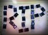
During the burn out the current would slowly rise. I used multiple resistors in series to keep the current close to 6mA but not over it. When it finally stabilized around 6mA I left it on for another 30min. Some cathodes went to 6mA right away and others (m, M and P) took more half hour just to get there. One of the resistors was always 1k so I could measure current by voltage drop:
@Neet Studio
MAX133/134 is a nice option but it requires a AC to DC circuit. It rectifies the AC and measures it as DC. I can do that, but it would work only with 50 or 60Hz sinusoidal and nothing else. But the datasheet has good information on how to protect the multimeter inputs! On my project I only have a fuse and filter.
I think I will have to include other circuits to enable all the measurements I want but I need to study on how to connect everything to the same jacks, change between the measurement circuits (some relays, maybe!?) and offer protection in case you plug 20V trying to measure capacitance or something like that.
I will check the websites you sent me tomorrow. Thanks!
Today I am able to read voltage at both sides of the shunt resistor, and then get current and power from there. Current has positive or negative signal depending on which side of the shunt has the lower voltage. The screen shows only the last one for 'voltage'.
Registered Member #1956
Joined: Wed Feb 04 2009, 01:22PM
Location: Jersey City
Posts: 172
I found this one very interesting mr. Destroyer
He states that for resistance and capacitor measurements the error is quite big, as much as 10% for capacitance! But it is just so neat to be able to just plug the component and the software recognizes what you plug in and how =)
For most of the non-RMS meters, the rectification is how they implement the AC scale. My old Beckman DMM and even the Fluke that I replaced it with has something very similar.
There are RMS converter chips out there. That's how my other multimeter does it conversion with the MAX133/134. Don't dismiss a chip because it is not built-in. Just the mux and the ADC in that chip is well worth the effort.
Linear Tech has a few of those converters: Analog Device:
There are DMM chip out there that does everything including LCD drivers, but that's not what you can interface: >In R/D/C (passive component) mode, resistance (including continuity), capacitance or diode measurements are allowed by fully automatic detection.
Take a look at the True RMS sample schematic and how they do it with an external chip and switch different functions to the 3 pole inputs.
Registered Member #1956
Joined: Wed Feb 04 2009, 01:22PM
Location: Jersey City
Posts: 172
Another small step: select measurement being displayed using a rotary encoder =)
Neet Studio: I look at the price for the MAX133: $12 per each! I am using the INA219, less than $3. I am trying some of the simpler circuits on the breadboard.
I have some IV-22 here (7-seg) and this IC you found it is giving me some ideas, involving a lot of smd transistors to solder =)
This site is powered by e107, which is released under the GNU GPL License. All work on this site, except where otherwise noted, is licensed under a Creative Commons Attribution-ShareAlike 2.5 License. By submitting any information to this site, you agree that anything submitted will be so licensed. Please read our Disclaimer and Policies page for information on your rights and responsibilities regarding this site.


 Nixie Digital MultiMeter