If you need assistance, please send an email to forum at 4hv dot org. To ensure your email is not marked as spam, please include the phrase "4hv help" in the subject line. You can also find assistance via IRC, at irc.shadowworld.net, room #hvcomm.
Support 4hv.org!
Donate:
4hv.org is hosted on a dedicated server. Unfortunately, this server costs and we rely on the help of site members to keep 4hv.org running. Please consider donating. We will place your name on the thanks list and you'll be helping to keep 4hv.org alive and free for everyone. Members whose names appear in red bold have donated recently. Green bold denotes those who have recently donated to keep the server carbon neutral.
Special Thanks To:
Aaron Holmes
Aaron Wheeler
Adam Horden
Alan Scrimgeour
Andre
Andrew Haynes
Anonymous000
asabase
Austin Weil
barney
Barry
Bert Hickman
Bill Kukowski
Blitzorn
Brandon Paradelas
Bruce Bowling
BubeeMike
Byong Park
Cesiumsponge
Chris F.
Chris Hooper
Corey Worthington
Derek Woodroffe
Dalus
Dan Strother
Daniel Davis
Daniel Uhrenholt
datasheetarchive
Dave Billington
Dave Marshall
David F.
Dennis Rogers
drelectrix
Dr. John Gudenas
Dr. Spark
E.TexasTesla
eastvoltresearch
Eirik Taylor
Erik Dyakov
Erlend^SE
Finn Hammer
Firebug24k
GalliumMan
Gary Peterson
George Slade
GhostNull
Gordon Mcknight
Graham Armitage
Grant
GreySoul
Henry H
IamSmooth
In memory of Leo Powning
Jacob Cash
James Howells
James Pawson
Jeff Greenfield
Jeff Thomas
Jesse Frost
Jim Mitchell
jlr134
Joe Mastroianni
John Forcina
John Oberg
John Willcutt
Jon Newcomb
klugesmith
Leslie Wright
Lutz Hoffman
Mads Barnkob
Martin King
Mats Karlsson
Matt Gibson
Matthew Guidry
mbd
Michael D'Angelo
Mikkel
mileswaldron
mister_rf
Neil Foster
Nick de Smith
Nick Soroka
nicklenorp
Nik
Norman Stanley
Patrick Coleman
Paul Brodie
Paul Jordan
Paul Montgomery
Ped
Peter Krogen
Peter Terren
PhilGood
Richard Feldman
Robert Bush
Royce Bailey
Scott Fusare
Scott Newman
smiffy
Stella
Steven Busic
Steve Conner
Steve Jones
Steve Ward
Sulaiman
Thomas Coyle
Thomas A. Wallace
Thomas W
Timo
Torch
Ulf Jonsson
vasil
Vaxian
vladi mazzilli
wastehl
Weston
William Kim
William N.
William Stehl
Wesley Venis
The aforementioned have contributed financially to the continuing triumph of 4hv.org. They are deserving of my most heartfelt thanks.
Registered Member #72
Joined: Thu Feb 09 2006, 08:29AM
Location: UK St. Albans
Posts: 1659
With the resonant charger, could I connect multiple ones in series? The output capacitor from one would feed into the other. I imagine that the capacitance would have to decrease as more sections were added to preserve the total energy stored in each stage. I really like the resonant charger.
You could, but it would be a waste of complexity. A DC power supply and a pulsed cap charger are really two very different animals. Use the round peg in the round hole, and the square peg in the square one.
What size of inductor would I need? Will it need to be iron core?
The energy storage of the inductor is governed by the energy going into the output caps, it must store 25% of the final output energy.
The value in uH governs the the length of the charging pulse, and the peak current that flows during charging. Fewer uH, more amps for the same energy storage, and the shorter the total length of the pulse.
Given that 100 shots/second = 100 half cycles = 50 full cycles per second, the freuqency is low enough in this application to use commercial mains iron, and it will certainly reduce the losses and size compare to trying to do it all air-core. Given that transformer cores and light ballasts are readily available, and have the right sort of inductance and voltage withstanding, why use anything else? Because a light ballast has to survive being connected to mains 24/7, its insulation must be good enough for the 2kV transients that hit from time to time.
The more I think about this application, the more I think that the output switch is a pain in the ace. Nice though the semi-resonant concept is, it really comes into its own when the voltage is higher. A vaguely related supply is the flyback, which also has a nice current output characteristic suitable for charging caps. The three advantages are that a) you could use a single switch, b) your primary supply could be recitified mains to save the space of a mains transformer, c) you still have transformer isolation, but executed at a small ferrite component rather than a big iron one. A further advantage for general purpose use is that it could form the basis for a more normal power supply.
So I'm thinking rectify mains, maybe through a doubler, to 320ish volts. Use a single 1600v IGBT as the primary switch, raising the 160 or 320 to say 1000v (a bit of headroom for the switch) at the primary through flyback action, which would give you 6kV on a 6:1 secondary winding. Use ferrite and several kHz switching. As the cap would need many cycles to charge, you would have the opportunity of pulse to pulse regulation.
Registered Member #543
Joined: Tue Feb 20 2007, 04:26PM
Location: UK
Posts: 4992
Turkey9 wrote ...
Thanks for all the replies!
A few questions:
With the resonant charger, could I connect multiple ones in series? The output capacitor from one would feed into the other. I imagine that the capacitance would have to decrease as more sections were added to preserve the total energy stored in each stage. I really like the resonant charger.
What size of inductor would I need? Will it need to be iron core?
It seems now the issue is generating the 2.5kV for the resonant charger. This could be a smps type of design, correct? As long as it can provide the current needed. I really would like to stay away from using a MOT as a power source as it is very big and bulky. However, it can be used as a step as I learn more of how to miniaturize everything.
For resonant charging to happen, the PRF must be double the resonant frequency of the LC tuned circuit formed by the charging choke combined with the capacitive element in the PFN.
In a word, there can be no hit and miss bodge with this kind of circuit.
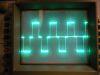
Richie Burnett gives a blow-by-blow account of resonant charging as it applies to TCs, but you'll see that even here there is no escape from timing accuracy if the technique is to work properly. There is only a brief instant on every cycle when the voltage is actually double, and the circuit must be made to fire then:
Registered Member #1064
Joined: Tue Oct 16 2007, 05:04PM
Location:
Posts: 42
The schematic shown uses D7 and D8. This circuit does not require that that the PFN be discharged at a specific frequency. The frequency can be as low as desired provided that the PFN capacitors are not discharge by leakage. Charging reactors with de-quing are sometimes used to obtain regulated voltage on the PFN capacitors.
Registered Member #543
Joined: Tue Feb 20 2007, 04:26PM
Location: UK
Posts: 4992
Carl Pugh wrote ...
The schematic shown uses D7 and D8. This circuit does not require that that the PFN be discharged at a specific frequency. The frequency can be as low as desired provided that the PFN capacitors are not discharge by leakage. Charging reactors with de-quing are sometimes used to obtain regulated voltage on the PFN capacitors.
Ah yes, I have mistakenly described conditions required for DC resonant charging without blocking diode, where PRF = 2fr
Registered Member #1451
Joined: Wed Apr 23 2008, 03:48AM
Location: Boulder, Co
Posts: 661
So if the power supply feeding the resonant charger can supply infinite current, then the inductor would change the charging frequency?
So far it seems like the main limitation of the resonant charger is the input voltage. I can see the the advantages go up exponentially as the input voltage increase, because there would be more voltage gained each cycle.
With the flyback method, would an input voltage of 12V be crippling, or would it just mean a larger primary to secondary ratio?
The application I'm looking at has to do with a project I've mentioned on 4hv a couple times. It's a electric propulsion system that I'm trying to shrink down to cubesat sizes. This means that the power supply needs to be able to fit in a 10cm cube. Lets assume that there is a magical 12V supply input that doesn't need to be accounted for. Would it be best to use a flyback charging circuit to reach the 5.5kV needed?
Registered Member #543
Joined: Tue Feb 20 2007, 04:26PM
Location: UK
Posts: 4992
I'm sorry that my suggestions haven't been of any use at all, Turkey, being more suited to rack mounting in steel cabinets....
However, it now seems to me that your best approach would be to first calculate the power density needed for your application, and then find out if any electrochemical or other energy sources of sufficient power density can be made to fit in your box with space to spare. Once you know that, but not before, you can make decisions about your high voltage generator.
Registered Member #56
Joined: Thu Feb 09 2006, 05:02AM
Location: Southern Califorina, USA
Posts: 2445
A flyback converter would work well for your application, and you would just have a comparator measuring the voltage on your capacitor (through a suitable resistive divider) that shuts down your gate drive when you reach the target voltage.
Registered Member #162
Joined: Mon Feb 13 2006, 10:25AM
Location: United Kingdom
Posts: 3141
From my point of view;
100mm x 100mm x100mm is plenty for a 150 W capacitor charger,
Some more detail is needed; - voltage, current, power rating of supply - type of current waveform allowed (if part of a system) (e.g. drawing power in low duty cycle pulses may not be allowed) - remote control? - cooling - connectors - ..........
I too would go for a 'flyback' design, the main problem being the switching transistor; - very low Rds(on) and switching losses - Voltage rating >= 10x Vdc (Toff/Ton) > (Vdc/Vflyback) for discontinuous mode and voltage rating > (Vdc + Vflyback) and you want (Toff/Ton) to be small (high duty cycle) to minimise peak switch current. Ipk > (Pav/Vdc) x 2 x (Ton + Toff)/Ton
The ferrite flyback transformer (e.g. ETD49) should be quite straightforward but at 5.5 kV should be in oil/wax/epoxy etc. with the rectifier.
For the control part, cycle-by-cycle control of the switch current (common in UC38xx controllers) would be best due to the nature of the load. (charging capacitance from 0V to Max dc repeatedly)
I would be concerned about the output rectifier being damaged by the discharge process, especially if there's any inductance in the load.
(I used the > sign a lot because efficiency <100%)
P.S. Despite the wealth of information and expertise available, smps design is non-trivial / many careers / a source of many failures.
Registered Member #1451
Joined: Wed Apr 23 2008, 03:48AM
Location: Boulder, Co
Posts: 661
Sulaiman wrote ...
Some more detail is needed; - voltage, current, power rating of supply - type of current waveform allowed (if part of a system) (e.g. drawing power in low duty cycle pulses may not be allowed) - remote control? - cooling - connectors - ..........
Ok here are some preliminary ideas... *Power supply can provide at least double the charger supply at 12V
*Any current waveform is allowed as the supply will be highly filtered and decoupled
*The charger will be monitored and controlled by an on-board micro that will receive commands from a computer
*Cooling will be by convection for now (normal heatsinks)
*Everything will be soldered together except the main supply input which will have connectors rated for the total supply power (binding posts most likely)
*switches would preferably be surface mount but larger TO-247 can be used
The caps that get charged will be discharged into an inductive load that will have a pretty small inductance (<10uH, more likely ~1uH). I'm playing with a design idea that will allow the capacitor voltage to swing to the full negative voltage with the RLC oscillations. I would think that this would not make the rectifiers from the charger happy, so it will probably be isolated from the pulse section somehow. Possibly with a string of avalanche rated switches? If my idea is even physically possible is still to be seen.
What kind of voltage increase per pulse on the caps will I see as the charger reaches the final voltage? I'm wondering how critical the speed of the comparator circuit cutting off the controller is.
Registered Member #162
Joined: Mon Feb 13 2006, 10:25AM
Location: United Kingdom
Posts: 3141
What kind of voltage increase per pulse on the caps will I see as the charger reaches the final voltage? I'm wondering how critical the speed of the comparator circuit cutting off the controller is. ............................. Assuming 150 W power output at 25 kHz, energy per pulse = 6 mJ 400nF @ 6kV = 7.2 J the next step in voltage would be from 7.2 J to 7.206 J sqrt(7.206/7.2) = 1.00041658 (E = 0.5.C.Vsquared) 6kV x 0.00041658 = 2.5 Volts per step, (flyback 'pulse' )
at 25 kHz the comparator should be faster than 40us to stop within one pulse but even a slow comparator would regulate the voltage to the limit of it's jitter.
This site is powered by e107, which is released under the GNU GPL License. All work on this site, except where otherwise noted, is licensed under a Creative Commons Attribution-ShareAlike 2.5 License. By submitting any information to this site, you agree that anything submitted will be so licensed. Please read our Disclaimer and Policies page for information on your rights and responsibilities regarding this site.


 Best regulation for 5.5kV power supply