
10KVA DRSSTC (Complete)
Goodchild, Wed Sept 22 2010, 04:03PMI'm starting this project thread for my newest project. The dead line for this project is The Winter Western Teslaton 2011, as I hope to be demoing it there with my other musical coils. This is the fifth DRSSTC I have built so far.
Well Ill start with some specs (as we all do with these project threads
 ):
): Secondary:
12.75 x 45 inches
24 AWG double build magnet wire
1/16 epoxy coating
Primary LC:
10 turns 3/8 copper tube water cooled
0.5uF 16Kv MMC (940C 1uF 2kv caps)
Topload:
12 x 45 inch tube/ring toroid very similar to Finn's and Steve's
System Fo (With topload):
40KHz
Power electronics:
Full bridge CM600HA-24H
GDT gate drive (no high side gate drive junk
 )
)650VDC bus (for now, later on I plan to have a PFC boost convert for this system at 750VDC)
Controller:
Steve Ward's UD 2.0
Interrupter:
My custom digital regular/MIDI Interrupter
OK now for some photos!
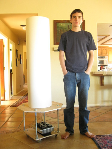
Me standing next to the un-wound secondary + the bare bones CM600 H bridge
Secondary end caps
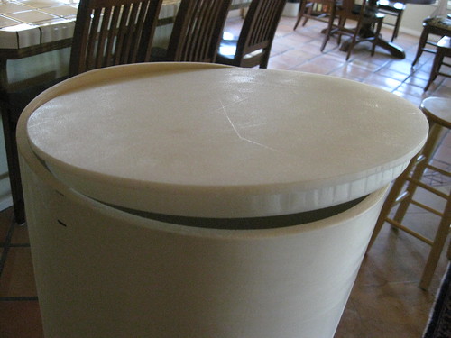
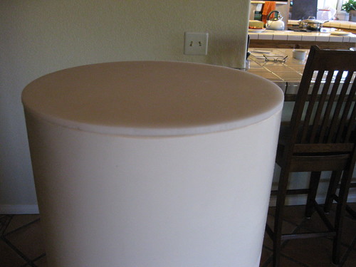
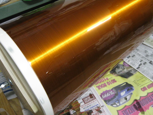
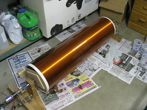
Winding the secondary:
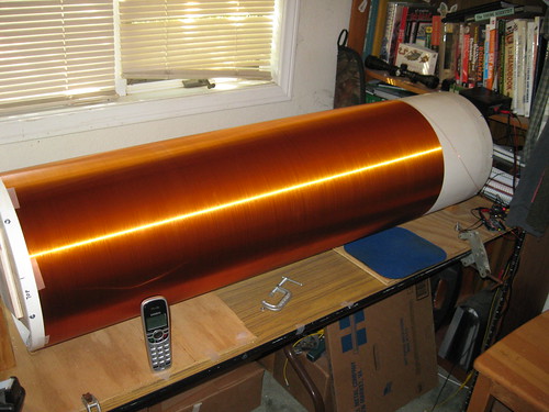
Epoxy on secondary:
Well that's all I have for now, I will update my progress as the build progresses. Don't hold your breath it's a long processes
More build photos here:

Re: 10KVA DRSSTC (Complete)
ScotchTapeLord, Wed Sept 22 2010, 04:21PM
That's a beautiful secondary. I'm working on a ~12" secondary with low Fres (26 gauge wire) that I'm eventually going to convert to solid state, but I could only get cardboard with dimensions like those. Where did you find PVC that wide?
ScotchTapeLord, Wed Sept 22 2010, 04:21PM
That's a beautiful secondary. I'm working on a ~12" secondary with low Fres (26 gauge wire) that I'm eventually going to convert to solid state, but I could only get cardboard with dimensions like those. Where did you find PVC that wide?
Re: 10KVA DRSSTC (Complete)
Goodchild, Wed Sept 22 2010, 04:54PM
I have a friend that got me this pipe at a local Irrigation supply. I did try Sono tube at one point, but it's just so much work to prep and never comes out the same as just strait PVC.
Goodchild, Wed Sept 22 2010, 04:54PM
I have a friend that got me this pipe at a local Irrigation supply. I did try Sono tube at one point, but it's just so much work to prep and never comes out the same as just strait PVC.
Re: 10KVA DRSSTC (Complete)
Jrz126, Wed Sept 22 2010, 05:35PM
wow, that is a smooth secondary. I have a similar sized one made with Sonotube. Now I wish I would've used PVC.
How do you plan on water cooling the primary? I'm in the process of converting mine to a DRSSTC, and using 3/8 would make things a lot easier and cheaper.
Re: 10KVA DRSSTC (Complete)
Goodchild, Wed Sept 22 2010, 05:57PM
Water cooling is easier than you mite think. I just got a small fountain pump, that will sit in a bucket of water next to the coil. I will pump water into one end of the primary tube and another tube will let the water flow back into the bucket. I will have some pics of this setup in a week or so when I build the primary.
Just wondering how much primary current do you plan on running?
Re: 10KVA DRSSTC (Complete)
Jrz126, Wed Sept 22 2010, 08:06PM
That's how I figured it'd be done. Seems like the conductivity of water would be an issue though.
As for my primary current, haven't really figured it out yet. I'm using some Uber-igbts, (2500V, 1200 Arms). So I think I can run just about anything.
Jrz126, Wed Sept 22 2010, 08:06PM
That's how I figured it'd be done. Seems like the conductivity of water would be an issue though.
As for my primary current, haven't really figured it out yet. I'm using some Uber-igbts, (2500V, 1200 Arms). So I think I can run just about anything.
Re: 10KVA DRSSTC (Complete)
Coronafix, Wed Sept 22 2010, 11:14PM
You might consider adding a old heat exchanger out of a fridge into your water cooling circuit. Some cpu fans would also greatly help.
Otherwise after a while, probably not very long, your pump will be pumping hot water back to the IGBTs.
Fantastic looking secondary.
Re: 10KVA DRSSTC (Complete)
Goodchild, Thu Sept 23 2010, 12:39AM
Ive seen the same thing done with 1/4 primary and the same current (even more heat) and only used a bucket of water, and it ran with almost no heating of the water.
Goodchild, Thu Sept 23 2010, 12:39AM
Coronafix wrote ...
You might consider adding a old heat exchanger out of a fridge into your water cooling circuit. Some cpu fans would also greatly help.
Otherwise after a while, probably not very long, your pump will be pumping hot water back to the IGBTs.
Fantastic looking secondary.
You might consider adding a old heat exchanger out of a fridge into your water cooling circuit. Some cpu fans would also greatly help.
Otherwise after a while, probably not very long, your pump will be pumping hot water back to the IGBTs.
Fantastic looking secondary.
Ive seen the same thing done with 1/4 primary and the same current (even more heat) and only used a bucket of water, and it ran with almost no heating of the water.
Re: 10KVA DRSSTC (Complete)
Dr. Drone, Thu Sept 23 2010, 04:24PM

Dr. Drone, Thu Sept 23 2010, 04:24PM

Re: 10KVA DRSSTC (Complete)
Goodchild, Thu Sept 23 2010, 05:10PM
On top of running at 40KHz the system will also use phase lead so there will we almost no voltage spikes or ringing.
Goodchild, Thu Sept 23 2010, 05:10PM
On top of running at 40KHz the system will also use phase lead so there will we almost no voltage spikes or ringing.

Re: 10KVA DRSSTC (Complete)
Steve Ward, Thu Sept 23 2010, 05:42PM
About water cooled primaries:
My research (both computer models and real tests) showed that going from 5/8" conductor to 3/8" conductor would be no efficiency hit (says computer FEM analysis), but real testing says *water cooled* 3/8" is less AC resistance, so more efficient, though the difference is small. Anyway, that result depends on keeping the conductor cool, whereas the 5/8" was not actively cooled so ran hotter (and thus, more resistive). The RAC (at a given temp) is basically the same despite the large reduction in surface area, because its in fact the large surface area that tends to have an unwanted effect of more eddy currents due to the coil's own magnetic flux. This is the reason why ribbon is generally not as good as tubing, though sort of for different reasons (namely, you can crowd the turns too densely).
So, our latest systems designed for our tesla coil shows use 3/8" copper with water pumped via $10 fountain pump from harbor freight tool. My attempt at measuring the leakage current through the water hose via CT was suggesting something like 500mA with 9kV peak on the primary. The same measurement repeated *without* the tube going through the CT, also said 500mA... so even the pearson 411A suffers from CM rejection issues in the presence of the primary coil. Anyway, the leakage current through a few feet water with a 1/2" diameter hose is negligible. As a precaution, i used a shielded power cable to the pump, and let the ground braid make contact with the water in my bucket/reservoir. Using about 3-4 gallons of water keeps the primary cool for about 30-45 minutes of constant running. Since our show is usually not more than an hour long, and the coils dont run 100% of the time, this works out to be plenty adequate, so no real need for a heat exchanger.
Re: 10KVA DRSSTC (Complete)
Goodchild, Thu Sept 23 2010, 08:32PM
This is very interesting, so basically you are grounding the water to earth to prevent primary current from getting into the water bucket and into the pump and into the mains AC and such.
Just wondering Steve ware your test with regular tap water or distilled water? Because with my tests with water and high voltage, distilled water actually makes a good isolator for the most part.
None the less all good information to take into account.
Re: 10KVA DRSSTC (Complete)
Shrad, Thu Sept 23 2010, 09:22PM
just use distilled water if you don't want electrolysis to occur
you also want a big flow so if you can, make a closed loop circuit and use a chiller and fan from a car or a shop fridge (easy to grab)
they use water cooling in laser power supplies, involving CW 300V 30A, sometimes pulsed or different voltages, and these issues are overcome with distilled water or deionized water
just my piece of advice from my personal field ;)
Re: 10KVA DRSSTC (Complete)
Steve Ward, Fri Sept 24 2010, 06:17PM
I used tap water. Also have used well water and other stuff that I bet most people wouldnt want to use for water cooling electronics. Even if the leakage current was an amp, it'd hardly matter since the bridge duty cycle is so low. I wouldnt bother with distilled water since its gonna get a bunch of stuff in it anyway once you run it through the primary.
The grounding of the water bucket was mainly in case i got a streamer hit to it, rather than have it inject current into the primary or pump, it could get back to RF ground as needed.
Re: 10KVA DRSSTC (Complete)
Goodchild, Mon Dec 20 2010, 05:27AM
Over the past week Steve Caton and my self got a lot of work done on this coil and also a twin that Steve is building. Yes you heard it right twin 10KVA DRSSTC.
Over some free time that we had over winter break we constructed the toroids, primarys, bases, and also finished both secondarys. It didn't hit me till now how big of a coil this really was until the toroid was finished and got put up top.
Here are some photos of the build:
Bending the tube for the toroid
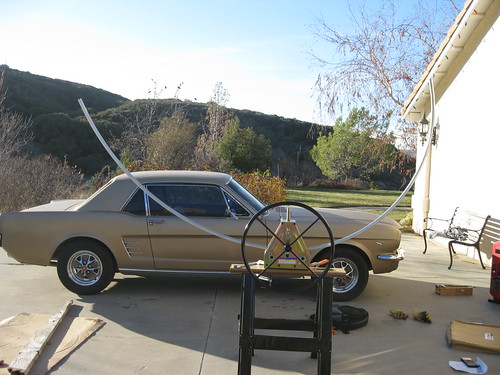
building the toroids
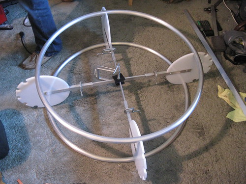
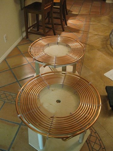
The primarys
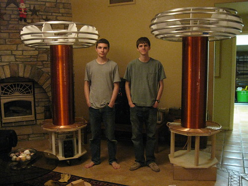
and finally Steve and my self standing next to our coils
Steve and his coil are on the right and my coil and I on the left
More images can be found here:
Goodchild, Mon Dec 20 2010, 05:27AM
Over the past week Steve Caton and my self got a lot of work done on this coil and also a twin that Steve is building. Yes you heard it right twin 10KVA DRSSTC.
Over some free time that we had over winter break we constructed the toroids, primarys, bases, and also finished both secondarys. It didn't hit me till now how big of a coil this really was until the toroid was finished and got put up top.
Here are some photos of the build:
Bending the tube for the toroid

building the toroids

The primarys

and finally Steve and my self standing next to our coils
Steve and his coil are on the right and my coil and I on the left

More images can be found here:

Re: 10KVA DRSSTC (Complete)
Finn Hammer, Mon Dec 20 2010, 06:14AM
Great work you are doing. I saw your photos on flickr, nice to see someone posting scope shots, keep doing that here as well.
Looking forward to seeing your solution when it comes to driving those CM600 gates!
Cheers, Finn Hammer
Finn Hammer, Mon Dec 20 2010, 06:14AM
Great work you are doing. I saw your photos on flickr, nice to see someone posting scope shots, keep doing that here as well.
Looking forward to seeing your solution when it comes to driving those CM600 gates!
Cheers, Finn Hammer
Re: 10KVA DRSSTC (Complete)
Ruben, Mon Dec 20 2010, 12:14PM
Really nice looking work so far.
I'm curious, what did you use to machine those toroid supports and secondary end caps?
Ruben, Mon Dec 20 2010, 12:14PM
Really nice looking work so far.
I'm curious, what did you use to machine those toroid supports and secondary end caps?
Re: 10KVA DRSSTC (Complete)
Goodchild, Mon Dec 20 2010, 06:08PM
We plan to use some rather large gate drive transformers to drive the gates of the CM600s. We came to this solution because of it's simplicity compared to high side gate drive. Ive driven large bricks in the past (such as CM300s) with GDTs and with great success, so I figured why could it not be applied here?
Yeah those end cap were a pain to make. I don't have access to a CNC or machine shop. We machined all of the parts for these coils using only hand tools, drill press, and a band saw.
Goodchild, Mon Dec 20 2010, 06:08PM
Great work you are doing. I saw your photos on flickr, nice to see someone posting scope shots, keep doing that here as well.
Looking forward to seeing your solution when it comes to driving those CM600 gates!
We plan to use some rather large gate drive transformers to drive the gates of the CM600s. We came to this solution because of it's simplicity compared to high side gate drive. Ive driven large bricks in the past (such as CM300s) with GDTs and with great success, so I figured why could it not be applied here?
Really nice looking work so far.
I'm curious, what did you use to machine those toroid supports and secondary end caps?
Yeah those end cap were a pain to make. I don't have access to a CNC or machine shop. We machined all of the parts for these coils using only hand tools, drill press, and a band saw.
Re: 10KVA DRSSTC (Complete)
RickR, Mon Dec 20 2010, 07:05PM
Nice looking coil(s)!
I've got a question though. Are you planning to connect the separate rings that constitute your topload together electrically? Otherwise it would seem to me that they would constitute independent single turn secondaries. If you are going to tie them together, how do you plan to do it? I'm asking because I'm planning to construct similar toroids but was going to use a continuous piece of copper tube wound in step fashion to produce the toroid. That way, individual rings wouldn't have to be connected together. I just couldn't think of a way to connect the individual rings that looked decent and at the same time was easy to assemble.
Thanks,
Rick
Re: 10KVA DRSSTC (Complete)
Dr. Drone, Mon Dec 20 2010, 07:22PM

Dr. Drone, Mon Dec 20 2010, 07:22PM

Re: 10KVA DRSSTC (Complete)
Goodchild, Mon Dec 20 2010, 10:28PM
RickR, yes connecting the rings electrically is a must! It's still on the todo list.
Dr. Spark I had a question for you. What do you use for your MMC parameters in Fatboy? I was particularly interested in the voltage rating of your MMC as it seems to have held up a long time at the power level you run at. Was just looking for a general comparison.
Also I'm doing my best to have it finished by WWT, if not you can be sure to see both of these coils at WWT 2012
Goodchild, Mon Dec 20 2010, 10:28PM
RickR, yes connecting the rings electrically is a must! It's still on the todo list.

Dr. Spark I had a question for you. What do you use for your MMC parameters in Fatboy? I was particularly interested in the voltage rating of your MMC as it seems to have held up a long time at the power level you run at. Was just looking for a general comparison.
Also I'm doing my best to have it finished by WWT, if not you can be sure to see both of these coils at WWT 2012
Re: 10KVA DRSSTC (Complete)
Sulaiman, Mon Dec 20 2010, 11:40PM
Lost for words, almost .. GREAT !
Thanks for sharing.
Sulaiman, Mon Dec 20 2010, 11:40PM
Lost for words, almost .. GREAT !
Thanks for sharing.
Re: 10KVA DRSSTC (Complete)
Dr. Drone, Tue Dec 21 2010, 12:26AM

Dr. Drone, Tue Dec 21 2010, 12:26AM

Re: 10KVA DRSSTC (Complete)
Arcstarter, Tue Dec 21 2010, 12:34AM
Nerdgasm.
Yours almost looks as good as Steve's... You just need that one last ring for the topload
Man, keep it up, i wanna see some sparks!
Arcstarter, Tue Dec 21 2010, 12:34AM
Nerdgasm.
Yours almost looks as good as Steve's... You just need that one last ring for the topload

Man, keep it up, i wanna see some sparks!
Re: 10KVA DRSSTC (Complete)
Goodchild, Tue Dec 21 2010, 12:40AM
Thanks every one for the complements, gives me more motivation to finish the thing
So DR Spark you use a 28KvDC bank? 14 x 2kv?
I am not looking to break any records with this coil. The goal of this coil is to have a supper reliably big DR that can reliably push out 10 or 11 feet. I'm looking foreword to seeing how well phase lead works out with CM600HA-24H at 40KHz it should be near perfect ZCS!
It would be way cool to see a FATBOY 2! There's nothing like running two very large DRSSTC at the same time.
Goodchild, Tue Dec 21 2010, 12:40AM
Dr. Spark wrote ...
I must say am a bit envious of your build however, as flat primary and phase compensation but think will keep the antique DRSSTC (FATBOY) and just start over on a new super design FATBOY 2 using Finn’s new phase controller. Kind of fun looking at old coils and reflecting where we were five years ago.
The MMC is a string of five times 14 banks. Have fans on both sides of MMC keeping them cool in Arizona summers. The area that will focus on FATBOY 2 is the bus between caps. There is a lot more RF than first designed for and get a bit of heating on the MMC bus @ 240vac in @ 185us duration. Have added a second bus over first but not a clean design. Get a big fat copper bus between banks as hard to go back and add more.
Great work guys, thanks for sharing!
Dr. Spark
Thanks every one for the complements, gives me more motivation to finish the thing

So DR Spark you use a 28KvDC bank? 14 x 2kv?
I am not looking to break any records with this coil. The goal of this coil is to have a supper reliably big DR that can reliably push out 10 or 11 feet. I'm looking foreword to seeing how well phase lead works out with CM600HA-24H at 40KHz it should be near perfect ZCS!
It would be way cool to see a FATBOY 2! There's nothing like running two very large DRSSTC at the same time.
Re: 10KVA DRSSTC (Complete)
Dr. Drone, Tue Dec 21 2010, 01:00AM

Dr. Drone, Tue Dec 21 2010, 01:00AM

Re: 10KVA DRSSTC (Complete)
Goodchild, Tue Dec 21 2010, 05:55AM
Cool, thanks, that give me a good comparison of my MMC value.
Goodchild, Tue Dec 21 2010, 05:55AM
Dr. Spark wrote ...
String of five 942c20p15k gives me 10kv DC; here is a pic as 7 banks of five on one side and 7 banks of five on back side @ .
.
Rgs,
Dr. Spark
String of five 942c20p15k gives me 10kv DC; here is a pic as 7 banks of five on one side and 7 banks of five on back side @
 .
. Rgs,
Dr. Spark
Cool, thanks, that give me a good comparison of my MMC value.
Re: 10KVA DRSSTC (Complete)
Finn Hammer, Tue Dec 21 2010, 07:12AM
I am certainly not suggesting it can't. Thumper is driven by gate transformers, and did 13+ feet doing so. Even a 4:1 stepdown design, on 2 inch OD cores.
Somehow, I felt I didn't have the same fine controll over the turn on and off of the bricks, and had to use gate resistors to get there. To me, it was a step back from active gate drive, and that is why I am presently going back.
Still, good luck with yours, as a super reliable 10-11 footer machine you can´t loose with that design.
A note about designing the MMC:
Voltage across the MMC: Calculate impedance Z, of cap @ Fres. Then voltage across is ohms law @Ipeak.
Example:
Fres: 40kHz, Cpri. 1.5uF, Z=2.65ohm
Voltage across @1700Apeak: 4505Apeak
Steve Conner is the originator of this formula to estimate RMS current, a key parameter in MMC design,
Irms = 0.5*Ipk*sqrt(Ton*BPS)
I have had good results using the CD 940C12W1P5K-F.
I have used them for Museum OLTC running now for 5 years on end, and Thumper logging a more modest hours.
When I test the motor on the bench, I do so with only one of these caps, in series with suitable coil, and it begins to break down at 3500V, passing 1000Apeak! It is the voltage that kills them.
Cheers, Finn Hammer
Finn Hammer, Tue Dec 21 2010, 07:12AM
Goodchild wrote ...
We plan to use some rather large gate drive transformers to drive the gates of the CM600s. We came to this solution because of it's simplicity compared to high side gate drive. Ive driven large bricks in the past (such as CM300s) with GDTs and with great success, so I figured why could it not be applied here?
Great work you are doing. I saw your photos on flickr, nice to see someone posting scope shots, keep doing that here as well.
Looking forward to seeing your solution when it comes to driving those CM600 gates!
We plan to use some rather large gate drive transformers to drive the gates of the CM600s. We came to this solution because of it's simplicity compared to high side gate drive. Ive driven large bricks in the past (such as CM300s) with GDTs and with great success, so I figured why could it not be applied here?
I am certainly not suggesting it can't. Thumper is driven by gate transformers, and did 13+ feet doing so. Even a 4:1 stepdown design, on 2 inch OD cores.
Somehow, I felt I didn't have the same fine controll over the turn on and off of the bricks, and had to use gate resistors to get there. To me, it was a step back from active gate drive, and that is why I am presently going back.
Still, good luck with yours, as a super reliable 10-11 footer machine you can´t loose with that design.
A note about designing the MMC:
Voltage across the MMC: Calculate impedance Z, of cap @ Fres. Then voltage across is ohms law @Ipeak.
Example:
Fres: 40kHz, Cpri. 1.5uF, Z=2.65ohm
Voltage across @1700Apeak: 4505Apeak
Steve Conner is the originator of this formula to estimate RMS current, a key parameter in MMC design,
Irms = 0.5*Ipk*sqrt(Ton*BPS)
I have had good results using the CD 940C12W1P5K-F.
I have used them for Museum OLTC running now for 5 years on end, and Thumper logging a more modest hours.
When I test the motor on the bench, I do so with only one of these caps, in series with suitable coil, and it begins to break down at 3500V, passing 1000Apeak! It is the voltage that kills them.
Cheers, Finn Hammer
Re: 10KVA DRSSTC (Complete)
Patrick, Tue Dec 21 2010, 07:56AM
If you wanted total isolation, you could pump corn oil through the primary, then into a car/van transmission radiator, the radiator would sit in a large mass of water...that would give you absolute confidence of zero electrolysis, and 100% isolation. but, maybe you dont need it.
Re: 10KVA DRSSTC (Complete)
Goodchild, Tue Dec 21 2010, 05:12PM
You know Finn one other option I looked into that would give individual control back to each brick would be to use 4 GDTs one for each brick similar to how DR Spark dose it on FATBOY. In that way you could drive each GDT differently giving each brick it's own dead time phase shift ect... This way you would keep isolation and do away with all the extra isolated PSU circuity.
Just an idea.
Goodchild, Tue Dec 21 2010, 05:12PM
Finn Hammer wrote ...
I am certainly not suggesting it can't. Thumper is driven by gate transformers, and did 13+ feet doing so. Even a 4:1 stepdown design, on 2 inch OD cores.
Somehow, I felt I didn't have the same fine controll over the turn on and off of the bricks, and had to use gate resistors to get there. To me, it was a step back from active gate drive, and that is why I am presently going back.
Still, good luck with yours, as a super reliable 10-11 footer machine you can´t loose with that design.
A note about designing the MMC:
Voltage across the MMC: Calculate impedance Z, of cap @ Fres. Then voltage across is ohms law @Ipeak.
Example:
Fres: 40kHz, Cpri. 1.5uF, Z=2.65ohm
Voltage across @1700Apeak: 4505Apeak
Steve Conner is the originator of this formula to estimate RMS current, a key parameter in MMC design,
Irms = 0.5*Ipk*sqrt(Ton*BPS)
I have had good results using the CD 940C12W1P5K-F.
I have used them for Museum OLTC running now for 5 years on end, and Thumper logging a more modest hours.
When I test the motor on the bench, I do so with only one of these caps, in series with suitable coil, and it begins to break down at 3500V, passing 1000Apeak! It is the voltage that kills them.
Cheers, Finn Hammer
Goodchild wrote ...
We plan to use some rather large gate drive transformers to drive the gates of the CM600s. We came to this solution because of it's simplicity compared to high side gate drive. Ive driven large bricks in the past (such as CM300s) with GDTs and with great success, so I figured why could it not be applied here?
Great work you are doing. I saw your photos on flickr, nice to see someone posting scope shots, keep doing that here as well.
Looking forward to seeing your solution when it comes to driving those CM600 gates!
We plan to use some rather large gate drive transformers to drive the gates of the CM600s. We came to this solution because of it's simplicity compared to high side gate drive. Ive driven large bricks in the past (such as CM300s) with GDTs and with great success, so I figured why could it not be applied here?
I am certainly not suggesting it can't. Thumper is driven by gate transformers, and did 13+ feet doing so. Even a 4:1 stepdown design, on 2 inch OD cores.
Somehow, I felt I didn't have the same fine controll over the turn on and off of the bricks, and had to use gate resistors to get there. To me, it was a step back from active gate drive, and that is why I am presently going back.
Still, good luck with yours, as a super reliable 10-11 footer machine you can´t loose with that design.
A note about designing the MMC:
Voltage across the MMC: Calculate impedance Z, of cap @ Fres. Then voltage across is ohms law @Ipeak.
Example:
Fres: 40kHz, Cpri. 1.5uF, Z=2.65ohm
Voltage across @1700Apeak: 4505Apeak
Steve Conner is the originator of this formula to estimate RMS current, a key parameter in MMC design,
Irms = 0.5*Ipk*sqrt(Ton*BPS)
I have had good results using the CD 940C12W1P5K-F.
I have used them for Museum OLTC running now for 5 years on end, and Thumper logging a more modest hours.
When I test the motor on the bench, I do so with only one of these caps, in series with suitable coil, and it begins to break down at 3500V, passing 1000Apeak! It is the voltage that kills them.
Cheers, Finn Hammer
You know Finn one other option I looked into that would give individual control back to each brick would be to use 4 GDTs one for each brick similar to how DR Spark dose it on FATBOY. In that way you could drive each GDT differently giving each brick it's own dead time phase shift ect... This way you would keep isolation and do away with all the extra isolated PSU circuity.
Just an idea.
Re: 10KVA DRSSTC (Complete)
Goodchild, Sun Jan 02 2011, 06:44AM
UPDATE:
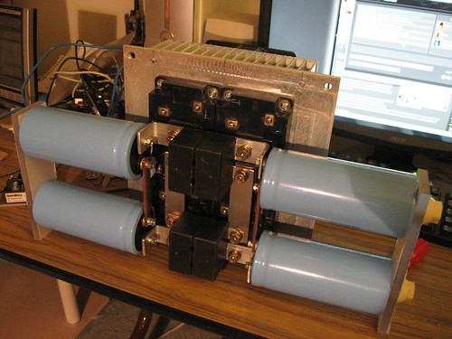
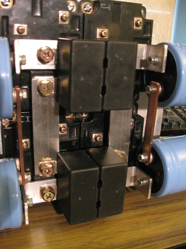
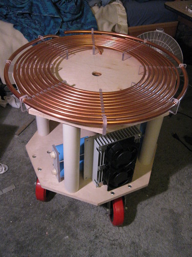
Well after some more work, the bridge and base are now mostly complete. The bus structure is 1/8" thick aluminum at the moment may swap it out for copper in the future. Also large casters added to base for easy movement. When complete I expect the coil to weigh a couple hundred lb, so those large caster will come in very handy.
I can get the toroid on without a ladder "thank god" but just barely. The next think to build is the MMC and all that is left after the MMC is final assembly and testing can't wait!
with the new casters the top of the secondary is about the same height as my head "about 6 feet" with the toroid on the coil will stand about 7.5 feet tall.


Re: 10KVA DRSSTC (Complete)
Steve Conner, Sun Jan 02 2011, 11:47AM
You seem to have a snubber cap across each IGBT. Are you sure you want to do that? In DRSSTCs, they're usually only placed across the DC bus.
Steve Conner, Sun Jan 02 2011, 11:47AM
You seem to have a snubber cap across each IGBT. Are you sure you want to do that? In DRSSTCs, they're usually only placed across the DC bus.
Re: 10KVA DRSSTC (Complete)
Gregory, Sun Jan 02 2011, 05:12PM
with a phase lead modern drive, the snubber capacitor in each igbt will be used???
Gregory, Sun Jan 02 2011, 05:12PM
with a phase lead modern drive, the snubber capacitor in each igbt will be used???
Re: 10KVA DRSSTC (Complete)
Goodchild, Sun Jan 02 2011, 05:42PM
The snubber caps are still technically across the DC bus but at 1/2 there value. Is there something wrong with having them across each IGBT?
Even though I am using phase lead I like to have snubbers just as insurance.
Goodchild, Sun Jan 02 2011, 05:42PM
The snubber caps are still technically across the DC bus but at 1/2 there value. Is there something wrong with having them across each IGBT?
Even though I am using phase lead I like to have snubbers just as insurance.
Re: 10KVA DRSSTC (Complete)
Gregory, Sun Jan 02 2011, 07:38PM
wrong no, but i think that the result isnt the best.. are you using steve ward ud2 driver? where can i get the schematic??
Gregory, Sun Jan 02 2011, 07:38PM
wrong no, but i think that the result isnt the best.. are you using steve ward ud2 driver? where can i get the schematic??
Re: 10KVA DRSSTC (Complete)
Goodchild, Sun Jan 02 2011, 08:38PM
Oh wait I see why having the snubber there can be bad, correct me if I'm wrong but this how I see it. some of the AC from the tank could find it's way back to the bus threw the snubber caps?
Just I thought. come to think of it ive never hooked a snubber up this way in a DR and ive built a lot of DRs.

Re: 10KVA DRSSTC (Complete)
Wolfram, Sun Jan 02 2011, 09:07PM
Yes, this is completely wrong, and will most likely explode the second you turn it on. Think of what happens when the lower IGBT in one leg of the bridge turns off and the upper one turns on.
Wolfram, Sun Jan 02 2011, 09:07PM
Gregory wrote ...
wrong no, but i think that the result isnt the best.. are you using steve ward ud2 driver? where can i get the schematic??
wrong no, but i think that the result isnt the best.. are you using steve ward ud2 driver? where can i get the schematic??
Yes, this is completely wrong, and will most likely explode the second you turn it on. Think of what happens when the lower IGBT in one leg of the bridge turns off and the upper one turns on.
Re: 10KVA DRSSTC (Complete)
Goodchild, Sun Jan 02 2011, 10:26PM
I see what you are saying thanks for pointing that out! will have to do a bit of updating on the bridge.
Goodchild, Sun Jan 02 2011, 10:26PM
I see what you are saying thanks for pointing that out! will have to do a bit of updating on the bridge.
Re: 10KVA DRSSTC (Complete)
Goodchild, Mon Mar 21 2011, 05:37PM
Ok I have not updated in a long time, but we had a very large jump in progress! Thus far I have completed the bridge, MMC, toroid, secondary, controller, and primary. All that is left to do is to mount it all to the base of the DR, for first light it was just sitting under the coil.
Steve Caton and my self standing next to my coil (I'm on right Steve on left) ready for first light!
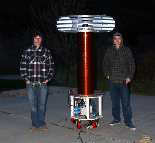
for reference I'm 5' 11" and my head just touches the bottom of the toroid. The coil is 7 feet tall.
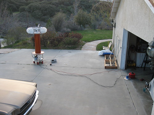
The overall first light set up on drive way with 30A 240VAC variac and doubler on the right.
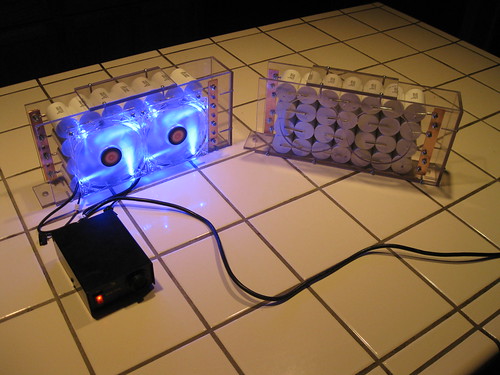
The MMCs for both Steve and my coils. One MMC is missing fans that will go on soon. We did our MMC Dr. Spark style
It makes sparks wooot!
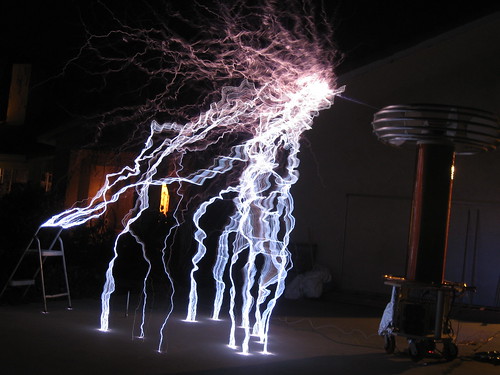
For reference that step stool is about 3 feet tall.
Good quality large spark photo:
Are expectation for first light were exceeded greatly! We expected this sort of performance from the coil after we had a tweaked system, but first light provided some nice juicy 10+ foot arcs in 20mph wind. We were also amazed at how efficient this system is, we had the OCD in the system set to 800Apk and we only occasionally tripped it when did burst mode. You heard me right <800Apk for 10+ feet. We thought this was an error at first but we confirmed that it was running less than 800Apk the whole time.
We powered the coil from the 240VAC line using a 30A variac and a voltage doubler, so that we would get 680VDC on the bridge. The coil really seemed to favor break rates between 100 bps to 200 bps. We also ran the PW at about 250uS - 300uS on average. With more tuning and tweaking we expect to see 12, 13 maybe even 14 feet out of this coil. We will have to put the coil up on a stand for longer arc, because as of now it loves to hit the ground
Here is a video of the coil running 10+ feet
More photo's of the build and running of the big coil:
We also plan to test run Steve Caton's coil in the coming summer which is basically a twin of this coil. It will be really awesome to see these two coil doing MIDI.
Goodchild, Mon Mar 21 2011, 05:37PM
Ok I have not updated in a long time, but we had a very large jump in progress! Thus far I have completed the bridge, MMC, toroid, secondary, controller, and primary. All that is left to do is to mount it all to the base of the DR, for first light it was just sitting under the coil.
Steve Caton and my self standing next to my coil (I'm on right Steve on left) ready for first light!

for reference I'm 5' 11" and my head just touches the bottom of the toroid. The coil is 7 feet tall.
The overall first light set up on drive way with 30A 240VAC variac and doubler on the right.

The MMCs for both Steve and my coils. One MMC is missing fans that will go on soon. We did our MMC Dr. Spark style


It makes sparks wooot!

For reference that step stool is about 3 feet tall.
Good quality large spark photo:

Are expectation for first light were exceeded greatly! We expected this sort of performance from the coil after we had a tweaked system, but first light provided some nice juicy 10+ foot arcs in 20mph wind. We were also amazed at how efficient this system is, we had the OCD in the system set to 800Apk and we only occasionally tripped it when did burst mode. You heard me right <800Apk for 10+ feet. We thought this was an error at first but we confirmed that it was running less than 800Apk the whole time.
We powered the coil from the 240VAC line using a 30A variac and a voltage doubler, so that we would get 680VDC on the bridge. The coil really seemed to favor break rates between 100 bps to 200 bps. We also ran the PW at about 250uS - 300uS on average. With more tuning and tweaking we expect to see 12, 13 maybe even 14 feet out of this coil. We will have to put the coil up on a stand for longer arc, because as of now it loves to hit the ground

Here is a video of the coil running 10+ feet

More photo's of the build and running of the big coil:

We also plan to test run Steve Caton's coil in the coming summer which is basically a twin of this coil. It will be really awesome to see these two coil doing MIDI.
Re: 10KVA DRSSTC (Complete)
Finn Hammer, Tue Mar 22 2011, 06:54AM
Extraordinary performance! Congratulations!
Long on-times you are running. Looks like it is a good idea to keep inductance high/current low. Another contender..
Cheers, Finn Hammer
Finn Hammer, Tue Mar 22 2011, 06:54AM
Extraordinary performance! Congratulations!
Long on-times you are running. Looks like it is a good idea to keep inductance high/current low. Another contender..
Cheers, Finn Hammer
Re: 10KVA DRSSTC (Complete)
Linas, Tue Mar 22 2011, 04:13PM
can you show how you mounted 1000V 2uF snubber's ?
Linas, Tue Mar 22 2011, 04:13PM
can you show how you mounted 1000V 2uF snubber's ?
Re: 10KVA DRSSTC (Complete)
Goodchild, Tue Mar 22 2011, 05:30PM
Sure, I decided to use 2 snubbers in parallel for 4uF at 1000V
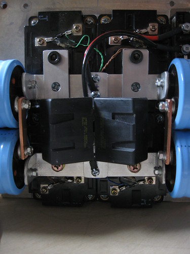
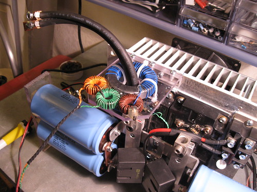
Also Finn, I believe there are two reasons why my primary current is so low. One the tank impedance is kinda high (12ohm) and also the coupling is high (0.25k) as a result of this I run longer on times at low peak currents, which I personal think is the better way to go, believe it or not currently I am running the CM600s lower than there datasheet rating of 1200A for 1mS. I think that it is better to run the IGBTs with slightly longer pulses at low peak current, my experience with the QCW is what lead me to this conclusion.
Also I am using a single 2 inch OD ferrite core for my GDT to drive all 4 CM600s this gate drive setup is working flawlessly so far, ill have to post some scope shots of the bridge output soon.
This coil also needs more C on the bus currently 2700uF is just not cutting it, we get some voltage sag at higher PW, I plan to double the C on the bus to 5400uF.
Goodchild, Tue Mar 22 2011, 05:30PM
Linas wrote ...
can you show how you mounted 1000V 2uF snubber's ?
can you show how you mounted 1000V 2uF snubber's ?
Sure, I decided to use 2 snubbers in parallel for 4uF at 1000V


Also Finn, I believe there are two reasons why my primary current is so low. One the tank impedance is kinda high (12ohm) and also the coupling is high (0.25k) as a result of this I run longer on times at low peak currents, which I personal think is the better way to go, believe it or not currently I am running the CM600s lower than there datasheet rating of 1200A for 1mS. I think that it is better to run the IGBTs with slightly longer pulses at low peak current, my experience with the QCW is what lead me to this conclusion.
Also I am using a single 2 inch OD ferrite core for my GDT to drive all 4 CM600s this gate drive setup is working flawlessly so far, ill have to post some scope shots of the bridge output soon.
This coil also needs more C on the bus currently 2700uF is just not cutting it, we get some voltage sag at higher PW, I plan to double the C on the bus to 5400uF.
Re: 10KVA DRSSTC (Complete)
Patrick, Tue Mar 22 2011, 07:57PM
Please forgive my ignorance, but why have you put those two large awg black wires through that blue wound toroid? Is that blue toriod for current measurement, or gate drive? Is your two inch diameter gate drive ferrite visible in the above pic?
Patrick, Tue Mar 22 2011, 07:57PM
Please forgive my ignorance, but why have you put those two large awg black wires through that blue wound toroid? Is that blue toriod for current measurement, or gate drive? Is your two inch diameter gate drive ferrite visible in the above pic?
Re: 10KVA DRSSTC (Complete)
Goodchild, Tue Mar 22 2011, 08:10PM
The blue wound toroid is for feedback and OCD, The GDT is not viable in the photos, it's behind the 2 blue caps on the left side of the heatsink.
Goodchild, Tue Mar 22 2011, 08:10PM
Patrick wrote ...
Please forgive my ignorance, but why have you put those two large awg black wires through that blue wound toroid? Is that blue toriod for current measurement, or gate drive? Is your two inch diameter gate drive ferrite visible in the above pic?
Please forgive my ignorance, but why have you put those two large awg black wires through that blue wound toroid? Is that blue toriod for current measurement, or gate drive? Is your two inch diameter gate drive ferrite visible in the above pic?
The blue wound toroid is for feedback and OCD, The GDT is not viable in the photos, it's behind the 2 blue caps on the left side of the heatsink.
Re: 10KVA DRSSTC (Complete)
vasil, Tue Mar 22 2011, 09:37PM
Awsome and well done! I liked your very detailed construction pics.
vasil, Tue Mar 22 2011, 09:37PM
Awsome and well done! I liked your very detailed construction pics.
Re: 10KVA DRSSTC (Complete)
Patrick, Wed Mar 23 2011, 12:13AM

Patrick, Wed Mar 23 2011, 12:13AM
Goodchild wrote ...
The blue wound toroid is for feedback and OCD, The GDT is not viable in the photos, it's behind the 2 blue caps on the left side of the heatsink.
I see now, I was wondering why your text didnt match the pic. Patrick wrote ...
Please forgive my ignorance, but why have you put those two large awg black wires through that blue wound toroid? Is that blue toriod for current measurement, or gate drive? Is your two inch diameter gate drive ferrite visible in the above pic?
Please forgive my ignorance, but why have you put those two large awg black wires through that blue wound toroid? Is that blue toriod for current measurement, or gate drive? Is your two inch diameter gate drive ferrite visible in the above pic?
The blue wound toroid is for feedback and OCD, The GDT is not viable in the photos, it's behind the 2 blue caps on the left side of the heatsink.

Re: 10KVA DRSSTC (Complete)
Dr. Drone, Wed Mar 23 2011, 08:35PM

Dr. Drone, Wed Mar 23 2011, 08:35PM

Re: 10KVA DRSSTC (Complete)
Patrick, Wed Mar 23 2011, 09:53PM
yes i too want to see what your heating condiontionshave turned out to be? has the liquid cooling decision been settled?
Patrick, Wed Mar 23 2011, 09:53PM
yes i too want to see what your heating condiontionshave turned out to be? has the liquid cooling decision been settled?
Re: 10KVA DRSSTC (Complete)
Goodchild, Wed Mar 23 2011, 11:50PM
The first light test was only at 800Apk and we didn't use water cooling, and the primary didn't get above ambient temperature.
800Apk is not enough to heat the 3/8 copper at all, we did not use water cooling on this run. When it's hotter outside and we start to run in 1000 to 1500Apk range we will then water cool the primary.
Yes you will have to make some room at WWT 2012 for these big guys! Also we though at first that the coil would like the lower bit rates but as we tested the coil it turns out that this coil really favors BPS in the 100 to 200Hz range. The sparks grew an extra 2 or 3 feet when we doubled the bit rate from 50Hz.
Re: 10KVA DRSSTC (Complete)
Dr. Drone, Thu Mar 24 2011, 03:06AM

Dr. Drone, Thu Mar 24 2011, 03:06AM

Re: 10KVA DRSSTC (Complete)
Coronafix, Thu Mar 24 2011, 05:20AM
Nice coil Goodchild. Good work!
Coronafix, Thu Mar 24 2011, 05:20AM
Nice coil Goodchild. Good work!
Re: 10KVA DRSSTC (Complete)
Goodchild, Thu Mar 24 2011, 06:28AM
I'm still working on a name, I'm open to suggestions if any one has got one? My current favorites are Andromeda and Isabella, I have not picked one yet though!
Overall we ran the coil for about 2 hours in 2 to 3 minuet burst, working bugs out and tuning her up.
I have not decided yet whether I want to go with solid state or iron, If I did go with iron it wouldn't have to be very big as we were only pulling about 18amps from the 240V mains. I probably will build a PFC for this coil just to say that I did and also to increases it's coolness factor. (PFC = coolness factor +1.5x)
If I do go with PFC I plan to go with a 4 channel interleaved phase type converter using 54amp TO-247 IGBTs. I like this kind of design because you don't need to have a giant core for the boost inductor (just 4 smaller cores) and you aren't limited to using big slow brick IGBTs that have high switching losses; and as an extra bonus the added phases help cancel out ripple on the input and output of the convertor. Building it would be a learning experience to say the least!
Goodchild, Thu Mar 24 2011, 06:28AM
Dr. Spark wrote ...
Well for 800RF Amps that thing is kicking ass.
Have you decided what to call her?
What was the duration running in pics, FATBOY was running at 150 with about 30% power at the thon or would have eating Hank’s ceiling.
Are you going to build a solid state controller or go with Iron?
It is kind of cool you both are building one as twins, will be wild and easier on the pocket book indeed.
Bringing a new surprise next year so FATBOY is going to stay home for a season and you will have lots of room to run indeed.
Again outstanding first light!
Best rgs,
Dr. Spark
I'm still working on a name, I'm open to suggestions if any one has got one? My current favorites are Andromeda and Isabella, I have not picked one yet though!
Overall we ran the coil for about 2 hours in 2 to 3 minuet burst, working bugs out and tuning her up.
I have not decided yet whether I want to go with solid state or iron, If I did go with iron it wouldn't have to be very big as we were only pulling about 18amps from the 240V mains. I probably will build a PFC for this coil just to say that I did and also to increases it's coolness factor. (PFC = coolness factor +1.5x)
If I do go with PFC I plan to go with a 4 channel interleaved phase type converter using 54amp TO-247 IGBTs. I like this kind of design because you don't need to have a giant core for the boost inductor (just 4 smaller cores) and you aren't limited to using big slow brick IGBTs that have high switching losses; and as an extra bonus the added phases help cancel out ripple on the input and output of the convertor. Building it would be a learning experience to say the least!

Re: 10KVA DRSSTC (Complete)
Dr. Drone, Thu Mar 24 2011, 04:24PM

Dr. Drone, Thu Mar 24 2011, 04:24PM

Re: 10KVA DRSSTC (Complete)
Goodchild, Thu Mar 24 2011, 05:31PM
Well I know why my controller reset on that wheel at WWT, the problem was that there is an improperly grounded MCU in that controller I may need to ground that better. The PFC though will have a dedicated PFC controller chip that is battle hardened for noisy environments.
The on time is rather high in this system because of the high inductance primary and lower primary current, we pushed maybe 250uS max on the first light run. Although this seems like a lot it's not all that bad because of the lower peak primary current.
Yeah she will be a power hog, she just needs some time to build up her appetite! We plan for our systems to handle 40A or more in there final configuration.
Re: 10KVA DRSSTC (Complete)
Steve Ward, Fri Mar 25 2011, 08:44PM
Id be careful about that CT you are using. Ive made many CTs, and any time ive used ones on cores of that geometry (they seem rather common actually), ive had sometimes fairly gross errors in both magnitude and phase. I only discovered this as i happened to move the CT around while the thing was running and i saw the display on the scope change by... a lot! A quick test of a selection of ferrites i had on hand showed my larger cores (that look like yours) had lower permeability compared to the cores i bought from TSC ferrite. I believe that lower permeability along with a fairly long magnetic path length makes the CT sort of a hybrid CT/rogowski coil, or essentially you are capturing not only B field from your cable, but also dB/dt (or Bdot), which is 90* out of phase which gives some phase error and magnitude error. It was interesting to transition between my old CTs (on the big open core) to a newer CT on a smaller high-perm core because i had to change my phase lead by a significant amount (needed more phase lead with the new core). But the new CT on the smaller core much better matched my pearson CT i use as a reference.
A miracle! breaking the laws of thermodynamics... careful Eric . Its easy to get excited when the primary feels just warm and didnt burn your hand, hooray! Id challenge you to run the thing for 10 minutes straight and re-check the temp.
With all that out of the way, congrats on a successful run! You've got the knack.
Its interesting to me that this coil is so very similar to my experimental coil in dimensions and Fo, but i used a 1.25uF tank cap and about half the pulse duration. I got 12' sparks pretty regularly, at about 1200A most of the time, and ~5kW from the PFC. It looks like your performance is nearly the same, but much different tank capacitance. Id like to see some scope shots of the primary (and also secondary base) current if you get a chance.
Steve Ward, Fri Mar 25 2011, 08:44PM
Id be careful about that CT you are using. Ive made many CTs, and any time ive used ones on cores of that geometry (they seem rather common actually), ive had sometimes fairly gross errors in both magnitude and phase. I only discovered this as i happened to move the CT around while the thing was running and i saw the display on the scope change by... a lot! A quick test of a selection of ferrites i had on hand showed my larger cores (that look like yours) had lower permeability compared to the cores i bought from TSC ferrite. I believe that lower permeability along with a fairly long magnetic path length makes the CT sort of a hybrid CT/rogowski coil, or essentially you are capturing not only B field from your cable, but also dB/dt (or Bdot), which is 90* out of phase which gives some phase error and magnitude error. It was interesting to transition between my old CTs (on the big open core) to a newer CT on a smaller high-perm core because i had to change my phase lead by a significant amount (needed more phase lead with the new core). But the new CT on the smaller core much better matched my pearson CT i use as a reference.
The first light test was only at 800Apk and we didn't use water cooling, and the primary didn't get above ambient temperature.
800Apk is not enough to heat the 3/8 copper at all, we did not use water cooling on this run. When it's hotter outside and we start to run in 1000 to 1500Apk range we will then water cool the primary.
A miracle! breaking the laws of thermodynamics... careful Eric
 . Its easy to get excited when the primary feels just warm and didnt burn your hand, hooray! Id challenge you to run the thing for 10 minutes straight and re-check the temp.
With all that out of the way, congrats on a successful run! You've got the knack.
Its interesting to me that this coil is so very similar to my experimental coil in dimensions and Fo, but i used a 1.25uF tank cap and about half the pulse duration. I got 12' sparks pretty regularly, at about 1200A most of the time, and ~5kW from the PFC. It looks like your performance is nearly the same, but much different tank capacitance. Id like to see some scope shots of the primary (and also secondary base) current if you get a chance.
Re: 10KVA DRSSTC (Complete)
Steve Conner, Fri Mar 25 2011, 09:01PM
Yay, I was hoping you would come along and give us your $.02 on that.
The story is that I decided to build high impedance coils with the tightest possible coupling driven by PLLs, but Steve Ward went with low impedance, looser coupling and a feedback driver. The two design choices lead to two quite different modes of operation: exciting mostly one mode with a long burst, as opposed to exciting both equally and shutting off at the resulting notch.
Steve claimed that his method was best, and since I had no coil throwing 12 foot sparks, and there was a sound theoretical basis to it, I could only agree. But if I ever do make a big one, I'll have to try it my way to see what happens.
Now here is a high impedance one that seems to work well, so I wonder what the deal is.
Re: 10KVA DRSSTC (Complete)
Goodchild, Sat Mar 26 2011, 05:13AM
Steve and Steve, both your inputs are greatly appreciated.
Steve Ward, I was worried about what you were talking about with the CT. I will have to recheck my CTs with one built on two of the same cores and see if this has any impact on the measurement. I do think though that my primary current was close to 800apk or at least <1000Apk. Now I know you are poking fun at my primary not getting hot, but.... we did run the coil for good 3 or 4 mins strait on one of our test and the primary was cold. I mean not even warm, the thing was ice cold with no water cooling. I would think that if the system was running more than 1000apk especially at the PW and break rates we ran that the primary would be at least a little warm after the run.
Steve Ward what you are saying about your test coil seems to make sense to me, from my view there are two ways you can run a DR as Steve McConner stated.
Mode one: lots of energy for a short amount of time.
Mode two: less energy for a longer period of time.
Ether way it seems as if you are putting the same amount of energy into the secondary on each burst. I went with mode two on this coil. The QCW and VTTC take advantage of this mode on a larger scale. This mode of operation has the nice little perk of being able to run higher couplings with less chance of a flashover. The QCW and VTTC run coupling in the 0.3 to 0.5 range without flashover.
I hate to use a water analog but the only way I can explain this effect is it's kinda like putting water in a bucket, if you fill the bucket up really fast you are going to spill water (flashover) but if you fill the bucket up slowly you are less likely to spill. In the end though there is still the same amount of water in the bucket.
I don't know if there is any truth to my logic but it seems to work!
I figured I would take advantage of this mode on a slightly less extreme level and apply it to a regular DR. The only real disadvantage this mode of operation is that you are increasing the RMS current in both the cap bank and IGBTs, but I believe that this can be compensated for with a good cooling setup on your IGBTs and tank cap and also a tank cap rated for a decent amount of RMS current.
The next time I run this coil I will set up a CT on the primary to monitor primary current and also one on the base to check the base current.
Thanks for the input, always keeping me on my toes!
Goodchild, Sat Mar 26 2011, 05:13AM
Steve Ward wrote ...
Id be careful about that CT you are using. Ive made many CTs, and any time ive used ones on cores of that geometry (they seem rather common actually), ive had sometimes fairly gross errors in both magnitude and phase. I only discovered this as i happened to move the CT around while the thing was running and i saw the display on the scope change by... a lot! A quick test of a selection of ferrites i had on hand showed my larger cores (that look like yours) had lower permeability compared to the cores i bought from TSC ferrite. I believe that lower permeability along with a fairly long magnetic path length makes the CT sort of a hybrid CT/rogowski coil, or essentially you are capturing not only B field from your cable, but also dB/dt (or Bdot), which is 90* out of phase which gives some phase error and magnitude error. It was interesting to transition between my old CTs (on the big open core) to a newer CT on a smaller high-perm core because i had to change my phase lead by a significant amount (needed more phase lead with the new core). But the new CT on the smaller core much better matched my pearson CT i use as a reference.
A miracle! breaking the laws of thermodynamics... careful Eric . Its easy to get excited when the primary feels just warm and didnt burn your hand, hooray! Id challenge you to run the thing for 10 minutes straight and re-check the temp.
With all that out of the way, congrats on a successful run! You've got the knack.
Its interesting to me that this coil is so very similar to my experimental coil in dimensions and Fo, but i used a 1.25uF tank cap and about half the pulse duration. I got 12' sparks pretty regularly, at about 1200A most of the time, and ~5kW from the PFC. It looks like your performance is nearly the same, but much different tank capacitance. Id like to see some scope shots of the primary (and also secondary base) current if you get a chance.
Id be careful about that CT you are using. Ive made many CTs, and any time ive used ones on cores of that geometry (they seem rather common actually), ive had sometimes fairly gross errors in both magnitude and phase. I only discovered this as i happened to move the CT around while the thing was running and i saw the display on the scope change by... a lot! A quick test of a selection of ferrites i had on hand showed my larger cores (that look like yours) had lower permeability compared to the cores i bought from TSC ferrite. I believe that lower permeability along with a fairly long magnetic path length makes the CT sort of a hybrid CT/rogowski coil, or essentially you are capturing not only B field from your cable, but also dB/dt (or Bdot), which is 90* out of phase which gives some phase error and magnitude error. It was interesting to transition between my old CTs (on the big open core) to a newer CT on a smaller high-perm core because i had to change my phase lead by a significant amount (needed more phase lead with the new core). But the new CT on the smaller core much better matched my pearson CT i use as a reference.
The first light test was only at 800Apk and we didn't use water cooling, and the primary didn't get above ambient temperature.
800Apk is not enough to heat the 3/8 copper at all, we did not use water cooling on this run. When it's hotter outside and we start to run in 1000 to 1500Apk range we will then water cool the primary.
A miracle! breaking the laws of thermodynamics... careful Eric
 . Its easy to get excited when the primary feels just warm and didnt burn your hand, hooray! Id challenge you to run the thing for 10 minutes straight and re-check the temp.
With all that out of the way, congrats on a successful run! You've got the knack.
Its interesting to me that this coil is so very similar to my experimental coil in dimensions and Fo, but i used a 1.25uF tank cap and about half the pulse duration. I got 12' sparks pretty regularly, at about 1200A most of the time, and ~5kW from the PFC. It looks like your performance is nearly the same, but much different tank capacitance. Id like to see some scope shots of the primary (and also secondary base) current if you get a chance.
Steve and Steve, both your inputs are greatly appreciated.
Steve Ward, I was worried about what you were talking about with the CT. I will have to recheck my CTs with one built on two of the same cores and see if this has any impact on the measurement. I do think though that my primary current was close to 800apk or at least <1000Apk. Now I know you are poking fun at my primary not getting hot, but.... we did run the coil for good 3 or 4 mins strait on one of our test and the primary was cold. I mean not even warm, the thing was ice cold with no water cooling. I would think that if the system was running more than 1000apk especially at the PW and break rates we ran that the primary would be at least a little warm after the run.
Steve Ward what you are saying about your test coil seems to make sense to me, from my view there are two ways you can run a DR as Steve McConner stated.
Mode one: lots of energy for a short amount of time.
Mode two: less energy for a longer period of time.
Ether way it seems as if you are putting the same amount of energy into the secondary on each burst. I went with mode two on this coil. The QCW and VTTC take advantage of this mode on a larger scale. This mode of operation has the nice little perk of being able to run higher couplings with less chance of a flashover. The QCW and VTTC run coupling in the 0.3 to 0.5 range without flashover.
I hate to use a water analog but the only way I can explain this effect is it's kinda like putting water in a bucket, if you fill the bucket up really fast you are going to spill water (flashover) but if you fill the bucket up slowly you are less likely to spill. In the end though there is still the same amount of water in the bucket.
I don't know if there is any truth to my logic but it seems to work!

I figured I would take advantage of this mode on a slightly less extreme level and apply it to a regular DR. The only real disadvantage this mode of operation is that you are increasing the RMS current in both the cap bank and IGBTs, but I believe that this can be compensated for with a good cooling setup on your IGBTs and tank cap and also a tank cap rated for a decent amount of RMS current.
The next time I run this coil I will set up a CT on the primary to monitor primary current and also one on the base to check the base current.
Thanks for the input, always keeping me on my toes!

Re: 10KVA DRSSTC (Complete)
Gregory, Sat Mar 26 2011, 04:52PM
The first DRSSTC I see running this method with really big sparks. But about tunnig? I think that dicferents methods can help to the "mode two" work fine.
What is your secondary ressonance frequency? and your primary frequency?
Gregory, Sat Mar 26 2011, 04:52PM
Mode two: less energy for a longer period of time.
The first DRSSTC I see running this method with really big sparks. But about tunnig? I think that dicferents methods can help to the "mode two" work fine.
What is your secondary ressonance frequency? and your primary frequency?
Re: 10KVA DRSSTC (Complete)
Finn Hammer, Sat Mar 26 2011, 08:35PM
Goodchild,
What's puzzeling me is that you run these long on-times while also having a high coupling.
Mode 3:4, energy transfer in 2.0 cycles: k= 0.2800000000
Mode 4:5, energy transfer in 2.5 cycles: k= 0.2195121951
If you have tuned for notches, you should see the first one at around 4.5 cycles. That is, @40kHz: 112uS, so you are really well beyond the 2nd. notch even with 250uS PW. It has been established, that there is no benefit in running more than the first notch, so it is going to be very interesting to hear about your primary and secondary resonant frequencies, as well as seing the primary current waveforms.
Cheers, Finn Hammer
Re: 10KVA DRSSTC (Complete)
Steve Conner, Sat Mar 26 2011, 09:08PM
Finn, that is the essence of the difference between "Mode 1" and "Mode 2".
In Mode 1 the burst length is exactly one "beat" of the two resonant frequencies. I don't know what happens if you carry on driving after the notch, but I seem to remember Steve W. told me it was something bad.
In Mode 2, the burst length is long compared to one beat. Because the coupling is tighter than Mode 1, and also because the burst is longer.
So the primary waveform has several notches, that just look like a ripple. Because the modes are driven unequally, one of them dies out and the ripple disappears, at which point you are "QCW" and, streamer loading and inverter I2T permitting, can continue driving as long as you like.
Really only the first one is anything like a "notch". My PLL driver would unbalance the two modes enough from the start that I never even got a first notch, just a kind of dent in the envelope.
Mode 2 is theoretically less efficient, but in practice it seems to work fine. Steve's QCW is an extreme example of a Mode 2 DRSSTC, but some of his other coils are extreme examples of Mode 1. They are points on a continuum, I'm sure you can make one that is Mode 1 and a half.

Re: 10KVA DRSSTC (Complete)
Finn Hammer, Sun Mar 27 2011, 08:09AM
AFAIU, the primary has to be tuned to the low pole to allow this mode to develop
Sure, when we slide the tapping point of Thumper past both modes we see this, even without being able to extract any hard evidence from it
Sheers, Finn Hammer
Finn Hammer, Sun Mar 27 2011, 08:09AM
Steve McConner wrote ...
Finn, that is the essence of the difference between "Mode 1" and "Mode 2".
In Mode 1 the burst length is exactly one "beat" of the two resonant frequencies. I don't know what happens if you carry on driving after the notch, but I seem to remember Steve W. told me it was something bad.
Daniel and I took a video of that, and it showed that we could save a lot of power input to the coil, without loosing streamer length, by cutting the PW to exactly the first notch. Thumper has lower coupling, so we setteled for 200uS.Finn, that is the essence of the difference between "Mode 1" and "Mode 2".
In Mode 1 the burst length is exactly one "beat" of the two resonant frequencies. I don't know what happens if you carry on driving after the notch, but I seem to remember Steve W. told me it was something bad.
wrote ...
In Mode 2, the burst length is long compared to one beat. Because the coupling is tighter than Mode 1, and also because the burst is longer.
Yes, but the primary and secondary are also not tuned to the same frequency, right?In Mode 2, the burst length is long compared to one beat. Because the coupling is tighter than Mode 1, and also because the burst is longer.
AFAIU, the primary has to be tuned to the low pole to allow this mode to develop
wrote ...
So the primary waveform has several notches, that just look like a ripple. Because the modes are driven unequally, one of them dies out and the ripple disappears, at which point you are "QCW" and, streamer loading and inverter I2T permitting, can continue driving as long as you like.
Really only the first one is anything like a "notch". My PLL driver would unbalance the two modes enough from the start that I never even got a first notch, just a kind of dent in the envelope.
I remember seing something like that, during tuning of the 6 musical coils. Seems so long time ago. I setteled for tuning the primary to the low pole since that was the wisdom of the time.....So the primary waveform has several notches, that just look like a ripple. Because the modes are driven unequally, one of them dies out and the ripple disappears, at which point you are "QCW" and, streamer loading and inverter I2T permitting, can continue driving as long as you like.
Really only the first one is anything like a "notch". My PLL driver would unbalance the two modes enough from the start that I never even got a first notch, just a kind of dent in the envelope.
wrote ...
Mode 2 is theoretically less efficient, but in practice it seems to work fine. Steve's QCW is an extreme example of a Mode 2 DRSSTC, but some of his other coils are extreme examples of Mode 1. They are points on a continuum, I'm sure you can make one that is Mode 1 and a half.
Mode 2 is theoretically less efficient, but in practice it seems to work fine. Steve's QCW is an extreme example of a Mode 2 DRSSTC, but some of his other coils are extreme examples of Mode 1. They are points on a continuum, I'm sure you can make one that is Mode 1 and a half.

Sure, when we slide the tapping point of Thumper past both modes we see this, even without being able to extract any hard evidence from it

Sheers, Finn Hammer
Re: 10KVA DRSSTC (Complete)
Steve Conner, Sun Mar 27 2011, 09:45AM
There are some relations between type of driver, primary tuning and mode of operation.
With a feedback driver: you get Mode 1 if the two coils are tuned the same, accounting for streamer capacitance. If you detune the primary in either direction, one of the two resonances starts to dominate and the notch gets shallower, tending towards Mode 2.
With a PLL you can't get Mode 1 at all as it has to choose one or other of the resonant frequencies. (the feedback driver can produce a waveform that contains both frequencies, but the PLL always oscillates at one frequency.) Detuning the primary makes no difference to this behaviour, it will always want to be Mode 2. A PLL driver should not be used for a coil designed to run in Mode 1.
In my old simulation work I ironically called Mode 2 "Ward Mode". Mode 1 was Antonio Mode, as Antonio de Queiroz showed that a notch could be created by tuning the PLL midway between the two resonant frequencies. But I couldn't get that to work: it's a zero, there is nothing for the PLL to lock to.
It is possible that the differences between modes 1 and 2 might get less significant as the streamer loading gets heavier.
With a PLL
Re: 10KVA DRSSTC (Complete)
Goodchild, Mon Mar 28 2011, 08:26PM
Well I finally got a chance to run the coil again, it's been raining the whole of last week.
I figured I would try some MIDI out on this coil just to see how it responded. Even though this coil needs long PW to make it's sparks MIDI seems to run on it very nicely.
I got some nice 10 foot sparks to ground and also the occasional 11 footer to the step still off to the right. The current limiter is still set to 800Apk with it only occasionally tripping during ground strikes.

The next time I run I plan to collect some data, my run last night was ended early due to the blistering cold wind.
Goodchild, Mon Mar 28 2011, 08:26PM
Well I finally got a chance to run the coil again, it's been raining the whole of last week.
I figured I would try some MIDI out on this coil just to see how it responded. Even though this coil needs long PW to make it's sparks MIDI seems to run on it very nicely.
I got some nice 10 foot sparks to ground and also the occasional 11 footer to the step still off to the right. The current limiter is still set to 800Apk with it only occasionally tripping during ground strikes.


The next time I run I plan to collect some data, my run last night was ended early due to the blistering cold wind.

Re: 10KVA DRSSTC (Complete)
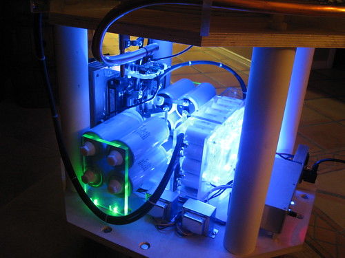
Goodchild, Fri May 20 2011, 05:27AM
Ok so I finally finished this coil I pimped it out with two LED fans and 1W LEDs
I did a little walk around video to show off all the awesome lighting. If you watch closely there is a surprise at the end!

Also Some photos

Goodchild, Fri May 20 2011, 05:27AM
Ok so I finally finished this coil I pimped it out with two LED fans and 1W LEDs
I did a little walk around video to show off all the awesome lighting. If you watch closely there is a surprise at the end!


Also Some photos


Re: 10KVA DRSSTC (Complete)
Dalus, Sun May 22 2011, 11:08AM
Looking good. Hopefully you'll figure out what mode is the best for this coil.
Dalus, Sun May 22 2011, 11:08AM
Looking good. Hopefully you'll figure out what mode is the best for this coil.
Re: 10KVA DRSSTC (Complete)
Goodchild, Sun May 22 2011, 04:32PM
Well this coil is still what it was originally. It runs the best the way it was originally designed.
Goodchild, Sun May 22 2011, 04:32PM
Dalus wrote ...
Looking good. Hopefully you'll figure out what mode is the best for this coil.
Looking good. Hopefully you'll figure out what mode is the best for this coil.
Well this coil is still what it was originally. It runs the best the way it was originally designed.

Re: 10KVA DRSSTC (Complete)
Dalus, Fri May 27 2011, 12:01PM
Nice to see that two completely different modes of operation can still yield these results. Was your coil easy to tune? Noticed my big coil needed to have the primary seriously detuned to compensate for the streamer loading. Took a while to find the sweet spot.
Do wonder how you play the chords. 2 tones I do understand but complete chords is something I don't grasp yet.
edit: Read your site. Just doing 2 tones per coil. Can grasp that

Re: 10KVA DRSSTC (Complete)
Goodchild, Fri May 27 2011, 05:35PM
Surprisingly I only moved the tap point 3 times I guess I got lucky.
2 notes and complete chords are played using the same logic, OR logic. You also have to decrease the PW of every note depending on how many notes you add. The more notes the shorter the PW has to be. This is to maintain a some what constant duty cycles depending.
Goodchild, Fri May 27 2011, 05:35PM
Dalus wrote ...
Nice to see that two completely different modes of operation can still yield these results. Was your coil easy to tune? Noticed my big coil needed to have the primary seriously detuned to compensate for the streamer loading. Took a while to find the sweet spot.
Do wonder how you play the chords. 2 tones I do understand but complete chords is something I don't grasp yet.
edit: Read your site. Just doing 2 tones per coil. Can grasp that

Surprisingly I only moved the tap point 3 times
 I guess I got lucky.
2 notes and complete chords are played using the same logic, OR logic. You also have to decrease the PW of every note depending on how many notes you add. The more notes the shorter the PW has to be. This is to maintain a some what constant duty cycles depending.
Re: 10KVA DRSSTC (Complete)
Dalus, Fri May 27 2011, 08:22PM
Same as the code that I've implemented then. Just limited to two notes per output at the moment. My coil is a pita when it comes to tuning. Each time I up the power it needs to be retuned for the streamer load.
Dalus, Fri May 27 2011, 08:22PM
Same as the code that I've implemented then. Just limited to two notes per output at the moment. My coil is a pita when it comes to tuning. Each time I up the power it needs to be retuned for the streamer load.
Print this page