
Magnetic levitation
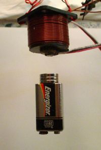
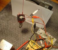
cjk2, Sat May 06 2006, 07:36PMHere is something I have been working on for the last few days. I got the idea after looking at Tesladownunder's site, and I decided to design my own circuit using the same basic idea. The outputs of the two hall effect sensors are subtracted from each other, then the difference is amplified and put through a lead compensation circuit for stability. The signal is then amplified again due to the loss in the lead compensation circuit, and is then fed into the DTC pin of a tl494 PWM chip set for around 30khz operation. The switching is done with rfp50n06 MOSFET. The coil is made of 18AWG magnet wire and is wound around a 5/8" solid steel core and plastic form. The spike generated by the coil when it is switched off is clamped by an ultrafast diode. The device will suspend up to around 5oz, and can support 1oz at about 1" away from the coil while drawing about 15w. The levitated object is farily stable due to the lead compensation circuit, even with no damper under it. Soon I want to use the remaining opamp in the lm324 to turn off the circuit when the levitated object falls or is pulled away.
Any comments/suggestions?

Re: Magnetic levitation
Tesladownunder, Sun May 07 2006, 12:56AM
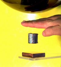
Nice work! The lead compensation (resistor/capacitor) is the key to the stability and was not present in the circuit I got this from originally. I had thought about doing a retrofit of my science museum maglev setup but it has been going fine for 18 months 8 hours a day 6 days a week so I am reluctant to mess with it. It remains a popular display and still no-one has pinched the magnet.
Your circuit is much simpler than Rick Hoadley's which I always thought was overly complicated.
I had plans for a PIC controlled setup with the original intention of controlling the instability but also to allow unusual actions such as the ability to place and leave a magnet in space.
Does your solid steel core get warm? You may have losses here compared with a laminated core but at 15 W it probably is not important. I have to have a very hefty fan in my setup to cope with the 75 - 300 W load in an enclosed magnet.
Peter

Re: Magnetic levitation
cjk2, Sun May 07 2006, 01:22AM
I was worried about losses, but nothing gets more than a little warm during normal operation. I am now rebuilding it to look better, so I should be posting some pictures soon. Maybe because the coil is not really AC but pulsed DC causes it to stay cool?
Right now it is levitating a .9oz stack of magnets 1" away from the coil and drawing .4a at 12v, so I guess it is a little more efficient than I thought.
Re: Magnetic levitation
Tesladownunder, Sun May 07 2006, 02:41AM
Would you be more efficient at a lower frequency? I only run 1kHz vs your 30kHz. Less back EMF pulses to be lost per second. On the other hand it is above the frequency response of the Hall device and may smooth the effect of the applied field from the electromagenet.
The addition of an alarm to sound when the magnet is removed is very useful for a public show. Particularly if this is graded in intensity as the magnet is pulled away.
I wonder if playing with the lead compensation resistor (ie making it variable) will allow you to tune for stability with different loads.
Peter
Re: Magnetic levitation
Maz, Sun May 07 2006, 02:55AM
O WOW congrats! i have always wanted to make a maglev
*suspiciously eyes up change jar
so i just might have to do that...
very good job indeed cjk2
Maz, Sun May 07 2006, 02:55AM
O WOW congrats! i have always wanted to make a maglev
*suspiciously eyes up change jar
so i just might have to do that...
very good job indeed cjk2
Re: Magnetic levitation
cjk2, Sun May 07 2006, 03:38AM
I did try using differnt frequencies down to about 1khz but I found it made an annoying sound at whatever frequency I had it runing at. Maybe this was just my power suppy(a moded ATX PSU) and not the levitation circuit. Anyway, in my final version which I am building now, I will put a large pot on the 494 so the frequency is adjustable from 30khz to the low khz range. It does seem to run cooler at lower frequencies. Changing the value of the lead compensation resistor didn't seem to do much, but it is hard to tell seeing as I am also adjusting gain at the same time. Right now I am just trying to cram it all on a small circuit board.
Re: Magnetic levitation
Carbon_Rod, Sun May 07 2006, 06:27AM
These are neat, IIRC some Hall effect devices performance is only rated at around 20KHz. I use them as no wear sensors when optical is not suitable.
I like the 3pin UGN3503 linear sensor with built in preamp (about 20KHz at +-900G). They will tie really nicely into an A/D unit (or th CV pin on a 555 )
I often use them for switches (cheap) -- but they will work for analog stuff too.
Fun stuff,
=]
Re: Magnetic levitation
Conundrum, Sun May 07 2006, 01:13PM
Cool :) now make it work upside down (i.e. levitate vertically) :)
hint:- you probably need three coils so you get a tripolar field to get around the earnshaw effect.
-A
Conundrum, Sun May 07 2006, 01:13PM
Cool :) now make it work upside down (i.e. levitate vertically) :)
hint:- you probably need three coils so you get a tripolar field to get around the earnshaw effect.
-A
Re: Magnetic levitation
cjk2, Mon May 08 2006, 01:05AM
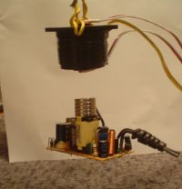
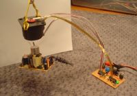
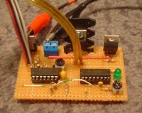
It is now rebuilt including a new board. It seems to run more effieciently this way, and maybe even a little cooler. The only problem I have now is that I seem to have lost some stablilty by rebuilding it. It still can be made more or less stable, but the gain has to be set just right, otherwise the magnet will either fall or stick to the core. Anyone have any ideas? The only thing I can think of is that maybe I put the in the lead compensation cap backwards(I am using a tantalum).
Things to do:
- Make it turn off when magnet is removed
- Solve stability problem
- Build a cool stand for it so I can sit it on my desk


Re: Magnetic levitation
ragnar, Mon May 08 2006, 01:39AM
I just LOVE the severed-board levitation 'target'...
Would you consider adding a small coil, rectifier and capacitor to the target so you can power e.g. LEDs on board? =-D
ragnar, Mon May 08 2006, 01:39AM
I just LOVE the severed-board levitation 'target'...
Would you consider adding a small coil, rectifier and capacitor to the target so you can power e.g. LEDs on board? =-D
Re: Magnetic levitation
TheMerovingian, Mon May 08 2006, 02:37PM
How it exactly works? The two sensors are placed in a way to have the same flux and then subtracted to obtain a zero (equilibrium signal) but with a coil current different from zero. When a magnet or a ferrous material approaches the bottom sensor the flux increases and having the sensor on the noninverting opamp input causes the current to decrease setting the active equilibrium. So also we need an offset setting to set the "no load" magnet current, does it is right?
Re: Magnetic levitation
Marko, Mon May 08 2006, 02:52PM
Maybe you could make it levitate another levitator instead of that board, pick the power from the coil and levitate another small magnet...
Marko, Mon May 08 2006, 02:52PM
Maybe you could make it levitate another levitator instead of that board, pick the power from the coil and levitate another small magnet...
Re: Magnetic levitation
Tesladownunder, Mon May 08 2006, 02:59PM
I suspect the lead compensation is dependent on the resting frequency of oscillation of the levitated mass. This will vary with the mass so you may find that a smaller mass like the battery you were using before might still be OK. Presumably bigger mass needs bigger cap.
Try levitating a non-magnetic object like a metal nut. I have levitated a wrench but couldn't keep it stable.
Peter
Re: Magnetic levitation
Wolfram, Mon May 08 2006, 03:08PM
CJK2, what sensors did you use on it?
Wolfram, Mon May 08 2006, 03:08PM
CJK2, what sensors did you use on it?
Re: Magnetic levitation
Self Defenestrate, Mon May 08 2006, 09:37PM
A quick thought, the system is a one sided transformer, so perhaps you could build a levitating peice with a coil inside, and power some l.e.d.'s in midair.
Self Defenestrate, Mon May 08 2006, 09:37PM
A quick thought, the system is a one sided transformer, so perhaps you could build a levitating peice with a coil inside, and power some l.e.d.'s in midair.
Re: Magnetic levitation
Part Scavenger, Mon May 08 2006, 10:30PM
The levitator IR LED circuit was one of the first circuits that I ever attempted. It never worked well due to lack of a good object to levitate, and changing light made it cranky. Yours is much cooler!
Part Scavenger, Mon May 08 2006, 10:30PM
The levitator IR LED circuit was one of the first circuits that I ever attempted. It never worked well due to lack of a good object to levitate, and changing light made it cranky. Yours is much cooler!

Re: Magnetic levitation
cjk2, Mon May 08 2006, 10:51PM
Yes, the output of the two sensors are subtracted from eachother so we see just the difference caused by the magnet. This voltage is then amplified up to 20 times, them fed through the lead compensator and amplified 10 times more. This "offset" would idealy be 0v and would cause the 494 to put out around a 90% on time duty cycle. In real life, the opamps can't get down to 0v so the actual voltage the DTC pin of the 494 sees is about .6v. This works out just fine, because it limits the max duty cycle to about 80% on. This keeps things from overheating.
Interesting idea, maybe ill try it sometime.
Thanks for the suggestion. I have now installed a small socket so I can easily change out cap values. With a little playing with, I can probably make it more stable. It can levitate nonmagnetic objects but it draws alot of power(like 40w in the picture below). It actually seems pretty stable this way.
The sensors are UGN3503U. I got them on ebay for $.75 each.
I tryed that but as soon as the coil gets more than 1/2" away, the led goes out. I think it will take another set of coils runing at a higher frequency to get the power any good distance.
Thanks!
Well I hope I anwsered all the questions, feel free to ask if you have any more.
Forgot to attach this....
maglev7.jpg
cjk2, Mon May 08 2006, 10:51PM
TheMerovingian wrote ...
How it exactly works? The two sensors are placed in a way to have the same flux and then subtracted to obtain a zero (equilibrium signal) but with a coil current different from zero. When a magnet or a ferrous material approaches the bottom sensor the flux increases and having the sensor on the noninverting opamp input causes the current to decrease setting the active equilibrium. So also we need an offset setting to set the "no load" magnet current, does it is right?
How it exactly works? The two sensors are placed in a way to have the same flux and then subtracted to obtain a zero (equilibrium signal) but with a coil current different from zero. When a magnet or a ferrous material approaches the bottom sensor the flux increases and having the sensor on the noninverting opamp input causes the current to decrease setting the active equilibrium. So also we need an offset setting to set the "no load" magnet current, does it is right?
Yes, the output of the two sensors are subtracted from eachother so we see just the difference caused by the magnet. This voltage is then amplified up to 20 times, them fed through the lead compensator and amplified 10 times more. This "offset" would idealy be 0v and would cause the 494 to put out around a 90% on time duty cycle. In real life, the opamps can't get down to 0v so the actual voltage the DTC pin of the 494 sees is about .6v. This works out just fine, because it limits the max duty cycle to about 80% on. This keeps things from overheating.
Firkragg wrote ...
Maybe you could make it levitate another levitator instead of that board, pick the power from the coil and levitate another small magnet...
Maybe you could make it levitate another levitator instead of that board, pick the power from the coil and levitate another small magnet...
Interesting idea, maybe ill try it sometime.
Tesladownunder wrote ...
I suspect the lead compensation is dependent on the resting frequency of oscillation of the levitated mass. This will vary with the mass so you may find that a smaller mass like the battery you were using before might still be OK. Presumably bigger mass needs bigger cap.
Try levitating a non-magnetic object like a metal nut. I have levitated a wrench but couldn't keep it stable.
Peter
Thanks for the suggestion. I have now installed a small socket so I can easily change out cap values. With a little playing with, I can probably make it more stable. It can levitate nonmagnetic objects but it draws alot of power(like 40w in the picture below). It actually seems pretty stable this way.
Anders M. wrote ...
CJK2, what sensors did you use on it?
CJK2, what sensors did you use on it?
The sensors are UGN3503U. I got them on ebay for $.75 each.
Self_Defenestrate wrote ...
A quick thought, the system is a one sided transformer, so perhaps you could build a levitating peice with a coil inside, and power some l.e.d.'s in midair.
A quick thought, the system is a one sided transformer, so perhaps you could build a levitating peice with a coil inside, and power some l.e.d.'s in midair.
I tryed that but as soon as the coil gets more than 1/2" away, the led goes out. I think it will take another set of coils runing at a higher frequency to get the power any good distance.
Part Scavenger wrote ...
The levitator IR LED circuit was one of the first circuits that I ever attempted. It never worked well due to lack of a good object to levitate, and changing light made it cranky. Yours is much cooler!
The levitator IR LED circuit was one of the first circuits that I ever attempted. It never worked well due to lack of a good object to levitate, and changing light made it cranky. Yours is much cooler!

Thanks!
Well I hope I anwsered all the questions, feel free to ask if you have any more.
Forgot to attach this....
maglev7.jpg
Re: Magnetic levitation
Wolfram, Tue May 09 2006, 09:31AM
How much weight can it hold?
Wolfram, Tue May 09 2006, 09:31AM
How much weight can it hold?
Re: Magnetic levitation
TheMerovingian, Tue May 09 2006, 10:13AM
I will limit the duty using the second tl494 comparator ( limiting the duty a 33% approx, correspondoing to 4A approx).
But would not the magnet suffer flux walking? Since each cicle che current does not fall to zero (dampner diode) che next cicle it will rise higher even with limited duty cicle. Wouldn't be necessary a current-mode control to avoid saturation? (this excludes the tl494 though..
)
I will try some calculations or spice simulations
TheMerovingian, Tue May 09 2006, 10:13AM
Yes, the output of the two sensors are subtracted from eachother so we see just the difference caused by the magnet. This voltage is then amplified up to 20 times, them fed through the lead compensator and amplified 10 times more. This "offset" would idealy be 0v and would cause the 494 to put out around a 90% on time duty cycle. In real life, the opamps can't get down to 0v so the actual voltage the DTC pin of the 494 sees is about .6v. This works out just fine, because it limits the max duty cycle to about 80% on. This keeps things from overheating.
I will limit the duty using the second tl494 comparator ( limiting the duty a 33% approx, correspondoing to 4A approx).
But would not the magnet suffer flux walking? Since each cicle che current does not fall to zero (dampner diode) che next cicle it will rise higher even with limited duty cicle. Wouldn't be necessary a current-mode control to avoid saturation? (this excludes the tl494 though..

)
I will try some calculations or spice simulations
Re: Magnetic levitation
Reaching, Tue May 09 2006, 10:28AM
mhh, thats a really cool project, im very impressed.
i tried many different ways to levitate an object but with poor results.
does anyone know if its possible to levitate a copper or aluminium disc stable via eddy currents(induction)?
Reaching, Tue May 09 2006, 10:28AM
mhh, thats a really cool project, im very impressed.
i tried many different ways to levitate an object but with poor results.
does anyone know if its possible to levitate a copper or aluminium disc stable via eddy currents(induction)?
Re: Magnetic levitation
TheMerovingian, Tue May 09 2006, 12:35PM
I have determined the formula for current given voltage, duty cicle, diode voltage drop and coil resistence (frequency and inductance doesn't seem to play a role)
It is used to set the max duty cicle on the tl494
I(rms) = (V * Df - Vd)/(R*(1+Df))
Vd is the diode voltage drop
Df is the duty factor (Ton/Toff or D/(1-D) where D is the duty cicle)
It is slightly less then expected using the simple V*D/R formula and it is due to the diode voltage drop
Setting Vd to zero produces the simple formula V*D/R that is good for a worst case estimation
Re: Magnetic levitation
Tesladownunder, Tue May 09 2006, 04:42PM
You can in fact pick up non-magnetic washers with an AC electromagnet with an additional copper washer added to the core. Now a levitator for aluminium objects would be really cool
Peter
Tesladownunder, Tue May 09 2006, 04:42PM
Reaching wrote ...
.. does anyone know if its possible to levitate a copper or aluminium disc stable via eddy currents(induction)?
It is possible to levitate a dish shaped copper or Al disc vertically but the power is large and the dish may be close to melting. I've not been able to manage it but 50Hz is rather low to work well... does anyone know if its possible to levitate a copper or aluminium disc stable via eddy currents(induction)?
You can in fact pick up non-magnetic washers with an AC electromagnet with an additional copper washer added to the core. Now a levitator for aluminium objects would be really cool

Peter
Re: Magnetic levitation
Reaching, Tue May 09 2006, 05:30PM
it works with 50hz and with a relative low current (around 5Amperes)
heres a video of a levitating heatsink, ok not really i need something to hold it in place.
the coil is directly connected to Mains, like a transformer

Reaching, Tue May 09 2006, 05:30PM
it works with 50hz and with a relative low current (around 5Amperes)
heres a video of a levitating heatsink, ok not really i need something to hold it in place.
the coil is directly connected to Mains, like a transformer

Re: Magnetic levitation
Hazmatt_(The Underdog), Tue May 09 2006, 10:37PM
when are you guys going to start making maglev led clocks? You know, spins while being levitated. That'd be pretty fun!
Hazmatt_(The Underdog), Tue May 09 2006, 10:37PM
when are you guys going to start making maglev led clocks? You know, spins while being levitated. That'd be pretty fun!
Re: Magnetic levitation
cjk2, Tue May 09 2006, 11:21PM
After some tweaking, it seems that to fix the stability problems, all I needed to do was lower the frequency a little. Perhaps to make it stable, the frequency has to be kept near the max frequency of the field effect sensor. Im not sure, but it is working very well now.
Re: Magnetic levitation
GimpyJoe, Tue May 09 2006, 11:29PM
It would be neat to put the whole thing in a vacuum and set the magnet spinning, just to see how long it would go. you would probably have to connect the coil to an aluminum bar which would connect to the base of the chamber, to sink heat.
GimpyJoe, Tue May 09 2006, 11:29PM
It would be neat to put the whole thing in a vacuum and set the magnet spinning, just to see how long it would go. you would probably have to connect the coil to an aluminum bar which would connect to the base of the chamber, to sink heat.
Re: Magnetic levitation
Tesladownunder, Wed May 10 2006, 01:07AM

My display maglev has spun for up to 90 minutes in air. Needs a very deft flick of the wrist though to keep it in the right spot but still rotating fast enough.
A 625k MPEG of the rotating magnet is here.
Peter
Tesladownunder, Wed May 10 2006, 01:07AM
Reaching wrote ...
it works with 50hz and with a relative low current (around 5Amperes)
heres a video of a levitating heatsink....

Thats a nice shot. With 550W input something will melt eventually though it works with 50hz and with a relative low current (around 5Amperes)
heres a video of a levitating heatsink....


My display maglev has spun for up to 90 minutes in air. Needs a very deft flick of the wrist though to keep it in the right spot but still rotating fast enough.
A 625k MPEG of the rotating magnet is here.
Peter
Re: Magnetic levitation
cjk2, Tue May 16 2006, 02:28AM
I consider the project 95% done at this point.
cjk2, Tue May 16 2006, 02:28AM
I consider the project 95% done at this point.
Re: Magnetic levitation
Tesladownunder, Sun May 21 2006, 04:42AM
Neat stuff. I am starting to get inspired to make one for a display at the University on their Open Day in a few months. My museum one is just a bit too much to drag down for the day.
This time I want BIG. Perhaps levitating a really big spanner or perhaps a notebook computer or radio. Or for real cool a small magnetic levitator.
I just need to get my other 500 projects out of the way first....
Peter
Re: Magnetic levitation
TheMerovingian, Fri Jul 14 2006, 01:00PM
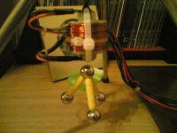
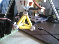
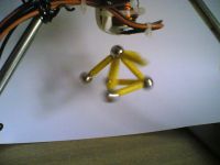
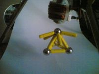
I have made a levitator with this principle , except using one error amplifier as buffer for limiting the duty cycle, using a PNP bipolar driven dyrectly by the tl494, and using a diode to kill the offset of the amplifier, making the amplification easier with less offset voltage. I have only problems with the magnet overheating (max current 1.3A, "usual current" 900mA). Maybe i should use more turns. Anyway it is able to levitate a supermag structure weighting 80grams at 1 cm from the core.


Re: Magnetic levitation
Petezel, Tue Jul 18 2006, 02:58PM
Hey, nice work!
 < have a poke at that, a clock where the display section 'floats'
Regards,
Pete
Petezel, Tue Jul 18 2006, 02:58PM
Hey, nice work!
 < have a poke at that, a clock where the display section 'floats'
Regards,
Pete
Re: Magnetic levitation
uzzors2k, Sun Oct 15 2006, 07:27PM
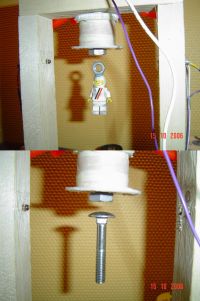
I just built one of these except I chose to use an infrared beam for object detection. One photo-transistor detects background and LED light while another detects whether the beam is broken. These two are compared and the result goes through a lead compensation circuit much like cjk2s. This signal then gets amplified and this controls the electro-magnet. Quite simple but once I got it running it was very stable with both heavy and light objects.
Things I can improve on it are the need for dual supply, overheating of drive transistor and make a proper housing. Otherwise it would be mantelpiece worthy!

Re: Magnetic levitation
teravolt, Sun Nov 12 2006, 03:29AM
Tesla Down Under what does the rest of your levitating shaded pole motor look like
teravolt, Sun Nov 12 2006, 03:29AM
Tesla Down Under what does the rest of your levitating shaded pole motor look like
Re: Magnetic levitation
Tesladownunder, Sun Nov 12 2006, 05:51AM
Not quite sure what you mean? Details here.
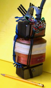
I now have an electromagnet that will support a NIB magnet at 17cm height with about 500W input power. This is compared with about 10cm max with the old magnet pictured below.
The new one is based on a cut down 2KVA 250 to 110V transformer.
Pic below is the old one.
Peter
Tesladownunder, Sun Nov 12 2006, 05:51AM
teravolt wrote ...
Tesla Down Under what does the rest of your levitating shaded pole motor look like
Nothing shady about my poles.Tesla Down Under what does the rest of your levitating shaded pole motor look like
Not quite sure what you mean? Details here.
I now have an electromagnet that will support a NIB magnet at 17cm height with about 500W input power. This is compared with about 10cm max with the old magnet pictured below.
The new one is based on a cut down 2KVA 250 to 110V transformer.
Pic below is the old one.
Peter

Re: Magnetic levitation
Dr. Dark Current, Wed Nov 15 2006, 04:13PM
Here is a circuit I designed, do you think it will work?
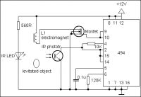
Dr. Dark Current, Wed Nov 15 2006, 04:13PM
Here is a circuit I designed, do you think it will work?

Re: Magnetic levitation
Steve Conner, Fri Nov 17 2006, 04:18PM
Due to the lack of catch diode across the magnet, I expect it would "A splode". Also that stuff about the TL494 needing pull-up or pull-down resistors on its outputs (can't remember which) and you forgot to put bypass capacitors on the supply rail too.
Steve Conner, Fri Nov 17 2006, 04:18PM
Due to the lack of catch diode across the magnet, I expect it would "A splode". Also that stuff about the TL494 needing pull-up or pull-down resistors on its outputs (can't remember which) and you forgot to put bypass capacitors on the supply rail too.
Re: Magnetic levitation
uzzors2k, Fri Nov 17 2006, 06:13PM
The quickest way is to simply try it.
uzzors2k, Fri Nov 17 2006, 06:13PM
Jmartis wrote ...
do you think it will work?
do you think it will work?
The quickest way is to simply try it.
Re: Magnetic levitation
Dr. Dark Current, Fri Nov 17 2006, 08:28PM
Dr. Dark Current, Fri Nov 17 2006, 08:28PM
Steve Conner wrote ...
Due to the lack of catch diode across the magnet, I expect it would "A splode". Also that stuff about the TL494 needing pull-up or pull-down resistors on its outputs (can't remember which) and you forgot to put bypass capacitors on the supply rail too.
thanks, so I built a circuit with these modifications, and by principle it works, but it is not stable (the levitated object sticks to the electromagnet above it)Due to the lack of catch diode across the magnet, I expect it would "A splode". Also that stuff about the TL494 needing pull-up or pull-down resistors on its outputs (can't remember which) and you forgot to put bypass capacitors on the supply rail too.
Re: Magnetic levitation
Marko, Fri Nov 17 2006, 08:32PM
With such 'flyback-ish' drive mosfet is surely going to absorb some HV spikes and heat up, but it probably won't blow up unless you push the frequency very high and power hard.
Putting diode or TVS across mosfet will just move the heat to another place, but that's probably the point.
Halfbridge drive would be much more efficient solution fr this.
Regarding pullups, with just one mosfet they aren't needed; just connect pin 10 to ground and pin 8 to mosfet, so you use TL's output transistors in push-pull.
Marko, Fri Nov 17 2006, 08:32PM
Steve Conner wrote ...
Due to the lack of catch diode across the magnet, I expect it would "A splode". Also that stuff about the TL494 needing pull-up or pull-down resistors on its outputs (can't remember which) and you forgot to put bypass capacitors on the supply rail too.
Due to the lack of catch diode across the magnet, I expect it would "A splode". Also that stuff about the TL494 needing pull-up or pull-down resistors on its outputs (can't remember which) and you forgot to put bypass capacitors on the supply rail too.
With such 'flyback-ish' drive mosfet is surely going to absorb some HV spikes and heat up, but it probably won't blow up unless you push the frequency very high and power hard.
Putting diode or TVS across mosfet will just move the heat to another place, but that's probably the point.
Halfbridge drive would be much more efficient solution fr this.
Regarding pullups, with just one mosfet they aren't needed; just connect pin 10 to ground and pin 8 to mosfet, so you use TL's output transistors in push-pull.
Re: Magnetic levitation
Steve Conner, Sat Nov 18 2006, 09:14PM
Did you see the earlier posts that mention the need for a lead compensation circuit to keep it stable?
BTW, merovingian mentioned the risk of "Flux Walking" in the magnet. Flux walking is exactly what you want in this system! It's the DC magnetic field that does the levitation. The controller walks the flux up to whatever level is needed to keep your object hovering at the desired height.
Any AC ripple at the switching frequency is just a nuisance. In practice due to the high frequency and high coil inductance, I expect there would be hardly any ripple, which explains why it's hard to extract power by magnetic coupling.
Steve Conner, Sat Nov 18 2006, 09:14PM
Jmartis wrote ...
it is not stable (the levitated object sticks to the electromagnet above it)
it is not stable (the levitated object sticks to the electromagnet above it)
Did you see the earlier posts that mention the need for a lead compensation circuit to keep it stable?
BTW, merovingian mentioned the risk of "Flux Walking" in the magnet. Flux walking is exactly what you want in this system! It's the DC magnetic field that does the levitation. The controller walks the flux up to whatever level is needed to keep your object hovering at the desired height.
Any AC ripple at the switching frequency is just a nuisance. In practice due to the high frequency and high coil inductance, I expect there would be hardly any ripple, which explains why it's hard to extract power by magnetic coupling.
Re: Magnetic levitation
Dr. Dark Current, Sat Nov 18 2006, 10:24PM
Dr. Dark Current, Sat Nov 18 2006, 10:24PM
Steve Conner wrote ...
Did you see the earlier posts that mention the need for a lead compensation circuit to keep it stable?
yep I saw those posts, but didnt have opamp(s) handy so I tried it without them, of course it didn't work. I will buy the LM324 and make the lead compensation (similar to cjk2's) but I have just one IR photodetector so I am not sure if it will work well.Jmartis wrote ...
it is not stable (the levitated object sticks to the electromagnet above it)
it is not stable (the levitated object sticks to the electromagnet above it)
Did you see the earlier posts that mention the need for a lead compensation circuit to keep it stable?
Re: Magnetic levitation
Dr. Dark Current, Mon Nov 20 2006, 04:08PM
I got the lm324 and built this circuit (original from cjk2), the white section is modified (in Paint ) :
) :

No, that does not work! I have tried adjusting both variable resistors, and haven't found a stability point (the levitated magnet bounces up and down couple times and then sticks to the electromagnet). Any ideas why it does not work??
Dr. Dark Current, Mon Nov 20 2006, 04:08PM
I got the lm324 and built this circuit (original from cjk2), the white section is modified (in Paint
 ) :
) :
No, that does not work! I have tried adjusting both variable resistors, and haven't found a stability point
 (the levitated magnet bounces up and down couple times and then sticks to the electromagnet). Any ideas why it does not work??
Re: Magnetic levitation
Steve Conner, Mon Nov 20 2006, 05:24PM
The gain (ie, change in output voltage per unit distance moved by the levitation target) of the phototransistor detector is probably far higher than the original Hall effect sensor, so the compensator can't cope. Uzzors obviously got it to work, so he should know how to modify the compensator to account for this.
Re: Magnetic levitation
Dr. Dark Current, Mon Nov 20 2006, 05:27PM
uzzors, I see you also used light beam to detect object's position. Could you please explain the changes you did to the circuit and how you got yours working?
Thanks.
Dr. Dark Current, Mon Nov 20 2006, 05:27PM
uzzors, I see you also used light beam to detect object's position. Could you please explain the changes you did to the circuit and how you got yours working?
Thanks.
Re: Magnetic levitation
uzzors2k, Mon Nov 20 2006, 05:55PM
I actually based my circuit around Barry's Magnetic Levitation . By the sound of things, you will need to adjust the compensation network, or just build a different circuit. 10K and 10µf are miles from what I had to use, you could try 150K and 100nf first. If that doesn't work, check my site.
I just added the Magnetic Levitator , so check it out if you need more guidance. You seem to have all the parts handy, just use a potenimeter to simulate the reference detector, if you don't have two IR detectors. Tell me how it goes!
uzzors2k, Mon Nov 20 2006, 05:55PM
I actually based my circuit around Barry's Magnetic Levitation
 . By the sound of things, you will need to adjust the compensation network, or just build a different circuit. 10K and 10µf are miles from what I had to use, you could try 150K and 100nf first. If that doesn't work, check my site.
I just added the Magnetic Levitator
 , so check it out if you need more guidance. You seem to have all the parts handy, just use a potenimeter to simulate the reference detector, if you don't have two IR detectors. Tell me how it goes!
Re: Magnetic levitation
Dr. Dark Current, Mon Nov 20 2006, 07:16PM
 , I built the circuit exactly as it is on your page, except I replaced the reference detector with a potentiometer (10kOhm, if that matters). I tried levitating a magnet and a metal nut, I also tried both bipolar and MOSFET output transistor, nothing seems to make difference. It is always exactly the same, as soon as you bring the object close to the light beam, it starts vibrating and bouncing around, and when you release it, it sticks to the electromagnet. Maybe I have some weird photodetector, because the "linear" object position region is very small (maybe half a mm).
If everything else fails, I'm going to find some Hall effect sensors and build that version instead.
EDIT: Do you think this will work for the Hall sensor version? (I'm especially not sure about hysteresis of this device and if it is wanted)
Dr. Dark Current, Mon Nov 20 2006, 07:16PM
uzzors wrote ...
I actually based my circuit around Barry's Magnetic Levitation . By the sound of things, you will need to adjust the compensation network, or just build a different circuit. 10K and 10µf are miles from what I had to use, you could try 150K and 100nf first. If that doesn't work, check my site.
I just added the Magnetic Levitator , so check it out if you need more guidance. You seem to have all the parts handy, just use a potenimeter to simulate the reference detector, if you don't have two IR detectors. Tell me how it goes!
Thanks for that circuit. I can't seem to get the damn thing to work I actually based my circuit around Barry's Magnetic Levitation
 . By the sound of things, you will need to adjust the compensation network, or just build a different circuit. 10K and 10µf are miles from what I had to use, you could try 150K and 100nf first. If that doesn't work, check my site.
I just added the Magnetic Levitator
 , so check it out if you need more guidance. You seem to have all the parts handy, just use a potenimeter to simulate the reference detector, if you don't have two IR detectors. Tell me how it goes!
 , I built the circuit exactly as it is on your page, except I replaced the reference detector with a potentiometer (10kOhm, if that matters). I tried levitating a magnet and a metal nut, I also tried both bipolar and MOSFET output transistor, nothing seems to make difference. It is always exactly the same, as soon as you bring the object close to the light beam, it starts vibrating and bouncing around, and when you release it, it sticks to the electromagnet. Maybe I have some weird photodetector, because the "linear" object position region is very small (maybe half a mm).
If everything else fails, I'm going to find some Hall effect sensors and build that version instead.
EDIT: Do you think this
 will work for the Hall sensor version? (I'm especially not sure about hysteresis of this device and if it is wanted)
Re: Magnetic levitation
uzzors2k, Mon Nov 20 2006, 08:04PM
Don't give up so easily! Mine behaved in just the same way until I got it figured out.
Try adjusting the poteniometer so its output voltage is exactly what the output from the beam detector is. Then put your hand in front of the beam and it should turn off.
Now that that is working, how heavy is the object you're levitating and does it block the entire beam? Its too heavy if it should fall after fluttering, and if its too light it will get sucked up. Find something that is just in between.
Once you've done that, the only room left for error is the lead compensation network. Try different resistor values, check here for more info.
You should be able to get it working, as it sounds like you're pretty close. Good luck!
uzzors2k, Mon Nov 20 2006, 08:04PM
Don't give up so easily!
 Mine behaved in just the same way until I got it figured out.
Try adjusting the poteniometer so its output voltage is exactly what the output from the beam detector is. Then put your hand in front of the beam and it should turn off.
Now that that is working, how heavy is the object you're levitating and does it block the entire beam? Its too heavy if it should fall after fluttering, and if its too light it will get sucked up. Find something that is just in between.
Once you've done that, the only room left for error is the lead compensation network. Try different resistor values, check here for more info.

You should be able to get it working, as it sounds like you're pretty close. Good luck!

Re: Magnetic levitation
Dr. Dark Current, Mon Nov 20 2006, 09:12PM
Well, so I replaced the resistors in the Phase lead network with potentiometers, got a big "fridge" magnet, and started adjusting these potentiometers while adjusting my electromagnet's height, and after about a hour of adjusting it worked!! well, at least for a while. After about 10 seconds the magnet started vibrating and then fell down. Maybe after some more adjusting I can get it stable but just for this only object. Just a little different magnet and is totally unstable without re-adjusting.
Edit- Now I tuned it stable. The output transistor is getting hot, probably operating in linear mode, here the tl494 comes for help (I do not have any more time right now, will play with it tomorrow)
Dr. Dark Current, Mon Nov 20 2006, 09:12PM
Well, so I replaced the resistors in the Phase lead network with potentiometers, got a big "fridge" magnet, and started adjusting these potentiometers while adjusting my electromagnet's height, and after about a hour of adjusting it worked!!
 well, at least for a while. After about 10 seconds the magnet started vibrating and then fell down. Maybe after some more adjusting I can get it stable but just for this only object. Just a little different magnet and is totally unstable without re-adjusting.
Edit- Now I tuned it stable. The output transistor is getting hot, probably operating in linear mode, here the tl494 comes for help
 (I do not have any more time right now, will play with it tomorrow)
Re: Magnetic levitation
uzzors2k, Mon Nov 20 2006, 10:26PM
Great Job!
My transistor is also running quite hot, I might need to upgrade to PWM like you. Also get a reference detector to further stabilize it, and its done!
uzzors2k, Mon Nov 20 2006, 10:26PM
Great Job!

My transistor is also running quite hot, I might need to upgrade to PWM like you. Also get a reference detector to further stabilize it, and its done!
Re: Magnetic levitation
Penguin7471, Sun Nov 26 2006, 05:58AM
Just out of curiosity as to just how unstable these things get, I built a "bare bones" levitator, which doesnt take differences of any signals nor have a compensation circuit. It uses a laser diode and LDR to sense the object's position. So basically... LDR-->transistor (turns on when no light) --> drives mosfet --> coil.
Sure enough, it is unstable as heck, and the object behaves like a woodpecker, slamming against the electromagnet before falling down then slamming on it again etc. etc.

Re: Magnetic levitation
Dr. Dark Current, Sun Nov 26 2006, 09:48AM
well, today I finished a "final" version of my levitator, built a nice wooden base for it, and a nice small circuit board with exactly the came circuit I had before. It has just one small downside, and thats that it is not stable
 . Even when I have everything the same except the base and the "frame" for the coil, when I turn the stabilisation pots on the circuit board in every possible direction and combination, I cannot get it stable. I think I will scrap it and build the hall sensor version, but the thing is I can't find any usable hall sensors. Crap.
Dr. Dark Current, Sun Nov 26 2006, 09:48AM
well, today I finished a "final" version of my levitator, built a nice wooden base for it, and a nice small circuit board with exactly the came circuit I had before. It has just one small downside, and thats that it is not stable

 . Even when I have everything the same except the base and the "frame" for the coil, when I turn the stabilisation pots on the circuit board in every possible direction and combination, I cannot get it stable. I think I will scrap it and build the hall sensor version, but the thing is I can't find any usable hall sensors. Crap.
Re: Magnetic levitation
Steve Conner, Sun Nov 26 2006, 03:15PM
You probably increased the gain of the system by moving the optics around. Maybe the target casts a sharper shadow on the photodiode now, or whatever.
Steve Conner, Sun Nov 26 2006, 03:15PM
You probably increased the gain of the system by moving the optics around. Maybe the target casts a sharper shadow on the photodiode now, or whatever.
Re: Magnetic levitation
uzzors2k, Sun Nov 26 2006, 03:41PM
You'll need to adjust it everytime you use it until you get a reference detector. Mine still works fine.
uzzors2k, Sun Nov 26 2006, 03:41PM
You'll need to adjust it everytime you use it until you get a reference detector. Mine still works fine.
Re: Magnetic levitation
Dr. Dark Current, Sun Nov 26 2006, 06:18PM
After many hours of tweaking and adjusting, I have it finally working stable with the new base. In the process I designed a simple circuit that works quite stable for me. All components, especially in the phase lead compensation circuit, were selected experimentally so I think it will not work "as is" on a different setup. I have yet to test if it also works stable in a daylight.

Re: Magnetic levitation
Kipmans, Fri Dec 08 2006, 05:00PM
cjk2, what is the resistance of your coil?
I'm also constructing a levitating device like yours, but my electromagnet (18 AWG) currently draws over 16 A at 5 V, overheating the wires. Even if I use all my wire (about 70 meters) It'll draw about 6,5 A. Do you think it'll be ok when it's actually PWM'ed?
Re: Magnetic levitation
cjk2, Sat Dec 09 2006, 03:15PM
Quite honestly, I have no idea if you will be alright with that type of coil. I think mine would draw something like 6 amps at 12v. I don't even think I ever measured the resistance, but i used something like 80' of 18awg wire. As long as the magnet does not actually have to provide that much force, the PWM circuit will be able to run with a low percentage of on time, so the magnet will not see that much power.
I'm about to have to leave, so I'm sorry I can't tell you any more. I'll back in a few hours, and Ill be happy to check the actual coil resistance, and tell you the percentage of on time the PWM tends to run at.
Re: Magnetic levitation
Kipmans, Sat Dec 09 2006, 06:27PM
Actually I made a mistake, I connected the coil to a 12 V source instead of 5 V when measuring the current . I added some more layers and now it draws 4 - 4,5 A at 5 V. The coil still gets pretty warm though, so I am still interested in your measurements.
Kipmans, Sat Dec 09 2006, 06:27PM
Actually I made a mistake, I connected the coil to a 12 V source instead of 5 V when measuring the current
 . I added some more layers and now it draws 4 - 4,5 A at 5 V. The coil still gets pretty warm though, so I am still interested in your measurements.
Re: Magnetic levitation
cjk2, Sat Dec 09 2006, 11:09PM
The resistance of my coil is about .5ohms. The on time is actually very low, usually under 20%. I bet this is due to the fact that the magnet is already strongly attracted to the core.
cjk2, Sat Dec 09 2006, 11:09PM
The resistance of my coil is about .5ohms. The on time is actually very low, usually under 20%. I bet this is due to the fact that the magnet is already strongly attracted to the core.
Re: Magnetic levitation
Kipmans, Wed Dec 13 2006, 12:58PM
I've been busy the past few days, hence the late reaction.
Thanks for the info, I'm pretty sure that my coil will be alright. It probably takes a lot of tweaking until the device eventually works, I will post here as soon as I made some progress.
Kipmans, Wed Dec 13 2006, 12:58PM
I've been busy the past few days, hence the late reaction.
Thanks for the info, I'm pretty sure that my coil will be alright. It probably takes a lot of tweaking until the device eventually works, I will post here as soon as I made some progress.
Re: Magnetic levitation
Tesladownunder, Wed Dec 13 2006, 02:10PM
I have put my HV stuff to one side for a while and have started work back on magnetic levitation where I left off 2 years ago with a PIC controlled system.
I have been going back trying to relearn PIC stuff first. I think this is the best way to go particularly if multiple sensors or outputs are needed with true levitation rather than suspension. The options for flexibility should be greater particularly if you are to do clever stuff like active movement or stay where it is placed stuff.
Peter
Re: Magnetic levitation
flannelhead, Sun Jul 06 2008, 03:14PM
Bringing the old but interesting topic up. I have a question: could hall switches (nonlinear; just on and off) used instead of linear hall effect sensors? Or do the sensors absolutely have to be linear?
flannelhead, Sun Jul 06 2008, 03:14PM
Bringing the old but interesting topic up. I have a question: could hall switches (nonlinear; just on and off) used instead of linear hall effect sensors? Or do the sensors absolutely have to be linear?
Re: Magnetic levitation
cjk2, Sun Jul 06 2008, 04:53PM
Using switches rather than sensors would probably lead to the object vibrating. Linear feedback is really needed for stable levitation.
cjk2, Sun Jul 06 2008, 04:53PM
Using switches rather than sensors would probably lead to the object vibrating. Linear feedback is really needed for stable levitation.
Re: Magnetic levitation
flannelhead, Mon Jul 07 2008, 08:17AM
Okay then. I'll just have to use infrared phototransistors. Hall sensors would've been so cool.
I'd want to get rid of the need for a dual power supply for the op-amps. Maybe a noobish question, but how could this be done?
flannelhead, Mon Jul 07 2008, 08:17AM
Okay then. I'll just have to use infrared phototransistors.
 Hall sensors would've been so cool.
 I'd want to get rid of the need for a dual power supply for the op-amps. Maybe a noobish question, but how could this be done?
Re: Magnetic levitation
Conundrum, Tue Jul 08 2008, 06:17PM
You can get linear sensors from old broken 5 1/4" floppy drives. Other sources include old style Panasonic VCRs (three are used in the capstan motor) as well as some hard drives.
There is a modern equivalent which is SMD, however its inferior in sensitivity and directionality to the 4 pin SIL equivalent.
It may also be possible to modify the read head on a hard drive (this consists of a very small nanowire) with a constant current as a magnetic sensor, though this is very finicky and hard to do.
Regards, -A
Re: Magnetic levitation
MagLev, Wed Oct 29 2008, 03:05PM
Actually, there are several types of levitators for aluminum (and, presumably, copper) objects. The book Propulsion Without Wheels by E.R. Laithwaite is an excellent source for these levitators. Unfortunately, the book is rare, expensive, and out-of-print. I had to get it through inter-library loan. The book is mainly about induction motors, but has a whole chapter just on magnetic levitation, with plenty of how-to diagrams and theory. It's a great resource.
Keep in mind, though, that any sort of induction levitator for copper, aluminum, or other diamagnetic materials will cause the materials to become hot if they are pushed deeper into the magnetic field than is necessary for them to levitate (i.e. an aluminum bowl which floats at 12 inches and stays cool will become very hot if pushed 6 inches into the magnetic field with a nonconducting object such as a wooden rod).
Here's a link to another aluminum levitator that works on the same principle. http://aether.lbl.gov/www/classes/p10/levitator.gif
MagLev, Wed Oct 29 2008, 03:05PM
Tesladownunder wrote ...
You can in fact pick up non-magnetic washers with an AC electromagnet with an additional copper washer added to the core. Now a levitator for aluminium objects would be really cool
Peter
Reaching wrote ...
.. does anyone know if its possible to levitate a copper or aluminium disc stable via eddy currents(induction)?
It is possible to levitate a dish shaped copper or Al disc vertically but the power is large and the dish may be close to melting. I've not been able to manage it but 50Hz is rather low to work well... does anyone know if its possible to levitate a copper or aluminium disc stable via eddy currents(induction)?
You can in fact pick up non-magnetic washers with an AC electromagnet with an additional copper washer added to the core. Now a levitator for aluminium objects would be really cool

Peter
Actually, there are several types of levitators for aluminum (and, presumably, copper) objects. The book Propulsion Without Wheels by E.R. Laithwaite is an excellent source for these levitators. Unfortunately, the book is rare, expensive, and out-of-print. I had to get it through inter-library loan. The book is mainly about induction motors, but has a whole chapter just on magnetic levitation, with plenty of how-to diagrams and theory. It's a great resource.
Keep in mind, though, that any sort of induction levitator for copper, aluminum, or other diamagnetic materials will cause the materials to become hot if they are pushed deeper into the magnetic field than is necessary for them to levitate (i.e. an aluminum bowl which floats at 12 inches and stays cool will become very hot if pushed 6 inches into the magnetic field with a nonconducting object such as a wooden rod).
Here's a link to another aluminum levitator that works on the same principle. http://aether.lbl.gov/www/classes/p10/levitator.gif
Re: Magnetic levitation
cjk2, Wed Oct 29 2008, 08:44PM
"Maglev", your link is broken. Now that this topic is active again, ill go ahead and post my most recent work. This is repulsive levitation.
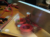
cjk2, Wed Oct 29 2008, 08:44PM
"Maglev", your link is broken. Now that this topic is active again, ill go ahead and post my most recent work. This is repulsive levitation.

Re: Magnetic levitation
101111, Wed Oct 29 2008, 09:41PM
Wow, That is impressive! Please, make a project thread out of it so we can see more ;)
101111, Wed Oct 29 2008, 09:41PM
cjk2 wrote ...
"Maglev", your link is broken. Now that this topic is active again, ill go ahead and post my most recent work. This is repulsive levitation.

"Maglev", your link is broken. Now that this topic is active again, ill go ahead and post my most recent work. This is repulsive levitation.

Wow, That is impressive! Please, make a project thread out of it so we can see more ;)
Re: Magnetic levitation
cjk2, Thu Oct 30 2008, 03:11AM
I will actually be updating rfhv.com soon to reflect my 5th version design. In the mean time, enjoy a picture of my controller board.
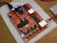
cjk2, Thu Oct 30 2008, 03:11AM
I will actually be updating rfhv.com soon to reflect my 5th version design. In the mean time, enjoy a picture of my controller board.

Re: Magnetic levitation
MagLev, Mon Jan 12 2009, 01:10AM
All righty, let's try to fix that link...
http://aether.lbl.gov/www/classes/p10/levitator.gif
Hopefully that'll do it. The device pictured here is very similar to a description of a levitator found in Harry F. Meiners' Physics Demonstration Experiments (more info can be found at Rick Hoadley's excellent magnet site- see link below.
http://www.coolmagnetman.com/magpie.htm
As he notes, a levitator like this is quite expensive and labor-intensive. However, they are quite fascinating to see in action. Here's a picture of one (with a funny comment about cooking pancakes).
http://blog.modernmechanix.com/mags/qf/c/PopularScience/11-1939/med_floating_bowl.jpg
Now to build/fix my own levitators when the parts arrive in a few days...
EDIT: Links still aren't working. Just copy and paste into your browser.
Re: Magnetic levitation
aonomus, Mon Jan 12 2009, 02:04PM
@ MagLev: Your links are incorrectly formatted (valid url, but you borked the bbcode)
As for the levitators, could a 'quick, dirty and cheap' version be made using MOT's perhaps with the top "I" sections ground off exposing the E section?
aonomus, Mon Jan 12 2009, 02:04PM
@ MagLev: Your links are incorrectly formatted (valid url, but you borked the bbcode)
As for the levitators, could a 'quick, dirty and cheap' version be made using MOT's perhaps with the top "I" sections ground off exposing the E section?
Re: Magnetic levitation
MagLev, Tue Jan 13 2009, 12:22AM
I've never seen a microwave oven transformer, so I am uncertain. However, I do know one thing: an essential component of eddy current levitators (which is what an aluminum or copper levitator is) is the requirement that there be (at least) two currents, and that the two currents be out of phase with each other. For instance, one type of levitator described in Propulsion Without Wheels involves levitating an aluminum sphere. To achieve this, the author recommends two methods. In the first, one coil is placed inside another, and the two are separated by some sort of iron ring or pipe (to concentrate the field). These two coils are then powered by different legs of a 3-phase supply, giving you two coils that are 120 degrees out of phase.
A variation on this (also described in the book) is where you have the same setup, with the difference being that the inner coil is replaced with a piece of very thick, solid (i.e. not split) copper pipe. In this case, current is induced in the copper pipe by virtue of the magnetic field generated by the first coil. So you still have some sort of phase difference between the outer coil (powered by AC) and the inner "coi", a.k.a. the pipe, which is "powered" by eddy currents.
Either one of these setups is used to levitate a small aluminum sphere.
A variation on this involves levitating a piece of aluminum shaped something like a dish or pie pan. This is described in Meiners' Physics Demonstration Experiments book. However, this one requires 3-phase power.
So I don't know about the MOTs- all I know is that there would need to be some sort of phase difference between different windings. Also, from my research, the shape and size of the object to be levitated is fairly critical, depending on your setup. That is, the sphere levitator described above will only levitate spheres of a specific size- it will not levitate discs, sheets, toroids, or whatever else. So I don't know what shape an "MOT levitator" would be best suited for, either.
Re: Magnetic levitation
BigBad, Sat Nov 27 2010, 07:53AM
Classic Laithwaite maglev video of his 'magnetic river'. Rather cool!

There's also a paper here:

that talks about Laithwaites lev stuff quite a bit.
BigBad, Sat Nov 27 2010, 07:53AM
Classic Laithwaite maglev video of his 'magnetic river'. Rather cool!

There's also a paper here:

that talks about Laithwaites lev stuff quite a bit.
Re: Magnetic levitation
BigBad, Fri Mar 16 2012, 05:45PM
FWIW a few months back I built a maglev set up using a combination of permanent magnets for the lift and a spinning aluminium disk giving the electrodynamic levitation for the stability. Air gap was about a centimeter.
I did some measurements of the drag on the aluminium from the magnets and it was only about 50-100 mN, so the overall lift power seems to be about a watt per kilogram, or so, and I could probably get it a lot lower.
Technically it was only pseudo levitation in the actual demo version, because I had to tether it laterally against the electrodynamic drag- my final version works like a train, so it will be pulled along by a propulsion system (probably a linear motor) rather than the tether.
Re: Magnetic levitation
BigBad, Sun Jul 22 2012, 09:44PM
This is pretty cute, albeit a bit wobbly looking because of the lumpy fields they're generating:
BigBad, Sun Jul 22 2012, 09:44PM
This is pretty cute, albeit a bit wobbly looking because of the lumpy fields they're generating:
Re: Magnetic levitation
invintive, Wed Oct 09 2013, 02:05AM
I know this is an old thread, but I am trying to build a magnetic levitator and I am a self taught electronics hobbyist (noob). Currently I have a working levitator, but it becomes quite unstable if it is disturbed at all. I am hoping to implement the feed forward circuit in the first post, but I am unfamiliar with OPAMPs. How am I supposed to power it? does it require a negative voltage?
Any comments, suggestions, or ideas would be greatly appreciated!
Print this page