
induction heater project - feedback on inverter.
Dinges, Mon Dec 28 2009, 02:55PMHello all,
After pondering for about a year I've decided to start constructing an induction heater. The first experiment, using a modified PC powersupply (http://4hv.org/e107_plugins/forum/forum_viewtopic.php?81329) was succesful, even though it was running at very limited power (100W input(measured), estimated 65W RF output).
The goal of the apparatus: about 1kW (but 500W would be satisfactory as well) output at a frequency of about 100 kHz. The topology will most likely be series tank circuit. I will use IRFP460 MOSFETs because that is what I have available (I'm saving the 4*4 pcs. MTE30NE50's on their 4 large cooling fins for a follow-up project, once all the errors are weeded out
 ). Input power will be 240Vac/50Hz. The intention is to build it right from the first time, as I hate rework/repair.... If needed (due to overheating), I will run it at reduced power - reliability and cool-running are more important than squeezing the last few watts out of it. It's meant to be a useful tool, an addition to my hobby shop, not something that should only 'sorta' work on the electronics bench.
My education and background is as mechanical engineer, not electrical, but know a thing or two about electronics, having tinkered with it from the age of 6. Let's just say I know which end of the soldering iron to hold, but designing high-power switchmode electronics is a tad more challenging than anything I've done so far (for an idea of some of my past projects, feel free to visit here: http://picasaweb.google.com/motorconversion). As this topic is pretty new to me, I'm looking for advice, input, comments, flamings, etc. on what I should do differently.
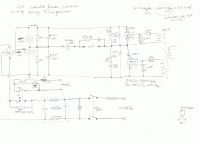
Above is the design of the inverter part that I have so far; it's only the powersection, the driver section and PLL will follow later. The schematic is a combination of things found in various places, but much of it comes from Richie Burnett (http://www.richieburnett.co.uk/sstate.html

Richie's is the only design I've seen using 1N5822 diodes in series with the FET. So the question is: how necessary are they? I know they work in combination with the MUR1660 (which I intend to replace with the HFA15TB60), but I normally only see freewheel diodes in the bridge schematics. Most likely I will add the 1N5822s (or rather, another set of HFA15TB60's on cooling fins, as I think the 1N5822 are underrated at 3A continuous for a 1kW inverter?)
So the questions:
- Is it ok to replace the 1N5822 with HFA15TB60s?
- how necessary are the 1N5822 diodes in practice?
- what is your opinion on the snubbers? Needed? Advised? Dimensions (resistance/capacity) seem ok?
- what other faults/errors/room for improvement is there in my preliminary schematic? Is there enough capacity (electrolytics)?
- how much cooling do you think the freewheel diodes and 'series' diode (1N5822) will need?
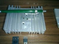
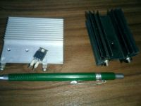
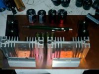
I intend to use the cooling fins below. A large one for each IRFP460 (2 total). By 'feel' I think it's big enough for the purpose, if not, let me know (I don't know how many K/W the fins are, but the large ones are 30x100x80mm). The smaller blank aluminium fins will be used for the HFA15TB60 'series' diodes (i.e. the 1N5822, if the HFA's are a suitable replacement in your opinions). The black fins are meant for the HFA15TB60 freewheel diodes (D-S of the IRFP460's)
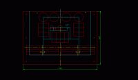
I intend to build the inverter on 1.58mm thick copper-clad epoxy board (FR4), with 'traces' milled. This should yield large conducting surfaces (wide traces/fields) with low inductance.
See the image below for the layout so far (note that the freewheeling and 1N5822 diodes still have to be added). The blue lines indicate milled paths. The two large rectangles at the bottom represent the cooling fins for the IRFP460 MOSFETs. The 4 round objects at the top are the electrolytics (4*470uF/200V). The smaller rectangular blocks are film capacitors.
I'm looking for all kinds of feedback that will help to improve the functionality and reliability of the apparatus. It's intended to end up as a stand-alone machine for use in my hobby workshop, meant to be foolproof. There is nothing I dislike more than needing a machine for a job and having to repair it first, so reliability is of prime importance.
Links to the datasheets for the various components I mentioned:
http://www.datasheetcatalog.org/datasheet/formosa/1N5822.pdf
http://www.datasheetcatalog.org/datasheet/irf/irfp460.pdf
http://www.datasheetcatalog.org/datasheet/motorola/MUR1620CT.pdf
http://www.datasheetcatalog.org/datasheet/irf/hfa15tb60.pdf
Sorry for the longwinded story, but I hate it when I read stories in forums where people only provide half the information; I think I've given all the relevant information, if not, please ask.
Looking forward to all advice, comments, links etc. that may help in the success of this project.
Peter.
Re: induction heater project - feedback on inverter.
GeordieBoy, Mon Dec 28 2009, 08:25PM
The schottky diodes in series with the MOSFETs are to block current flow through the MOSFET's intrinsic body-drain diodes which are very slow. The anti-parallel FRED then provides the new free-wheeling path for the load current when both MOSFETs are off during the deadtime. As for whether they are needed the definitive answer is "It depends!"
In short it depends on how the inverter is tuned relative to the resonant frequency of the tank circuit, and whether this is a parallel resonant or series resonant network.
If you use the LCLR work coil arrangement and control power throughput by detuning the drive frequency on the high side of the tank circuit's own resonant frequency then there is no requirement for blocking the MOSFET's body-drain diodes. The LCLR arrangement presents an inductive load to the inverter when detuned and MOSFETs like a net inductive load best. (You will find most power electronics books assume a net inductive load as inverters typically drive things like motors and transformers where this is a pretty good assumption. That's why the body-diode isolation and bypass often isn't covered.) If you can ensure that it is always tuned such that the load appears at least partly inductive then the load current lags the applied voltage from the inverter and the diodes never see forced reverse recovery. In this case the slow body-drain diodes are adequate.
In instances where the load current is in phase with the applied voltage or leads (net capacitive load) the load current changes direction before the voltage causing the free-wheel diodes to be subject to forced reverse recovery. The MOSFET body-drain diodes are not suitable for operation as FWDs in this mode of operation above a few kHz because of their lousy reverse recovery times. Forced reverse recovery causes huge current spikes at MOSFET turn-on, voltage overshoots, ringing and EMI problems, and often device failures.
In induction heaters I have designed I control the drive frequency to always be above the resonant frequency of the tank circuit, thus ensuring that the current always lags the applied voltage for the LCLR topology. This net inductive load is ideal for MOSFETs used in bridges and half-bridges as it achieves a mode of soft-switching known as ZVS. Zero voltage switching eliminates turn-on switching losses due to device output capacitances and diode reverse-recovery charge.
Again the requirement for snubbers depends entirely on how the converter is operated. If it was me, I would operate in the ZVS mode described above with lagging power factor and if necessary employ lossless snubbing capacitors directly across the MOSFETs. But, to be honest if you haven't got EMI targets to meet, you can probably dispense with the dv/dt limiting and just let the inverter do it's things. Zero voltage switching is a pretty clean way of running the inverter anyway.
If you want to learn more about induction heating power electronics I'd recommend reading the following two papers:


-Richie,
GeordieBoy, Mon Dec 28 2009, 08:25PM
The schottky diodes in series with the MOSFETs are to block current flow through the MOSFET's intrinsic body-drain diodes which are very slow. The anti-parallel FRED then provides the new free-wheeling path for the load current when both MOSFETs are off during the deadtime. As for whether they are needed the definitive answer is "It depends!"

In short it depends on how the inverter is tuned relative to the resonant frequency of the tank circuit, and whether this is a parallel resonant or series resonant network.
If you use the LCLR work coil arrangement and control power throughput by detuning the drive frequency on the high side of the tank circuit's own resonant frequency then there is no requirement for blocking the MOSFET's body-drain diodes. The LCLR arrangement presents an inductive load to the inverter when detuned and MOSFETs like a net inductive load best. (You will find most power electronics books assume a net inductive load as inverters typically drive things like motors and transformers where this is a pretty good assumption. That's why the body-diode isolation and bypass often isn't covered.) If you can ensure that it is always tuned such that the load appears at least partly inductive then the load current lags the applied voltage from the inverter and the diodes never see forced reverse recovery. In this case the slow body-drain diodes are adequate.
In instances where the load current is in phase with the applied voltage or leads (net capacitive load) the load current changes direction before the voltage causing the free-wheel diodes to be subject to forced reverse recovery. The MOSFET body-drain diodes are not suitable for operation as FWDs in this mode of operation above a few kHz because of their lousy reverse recovery times. Forced reverse recovery causes huge current spikes at MOSFET turn-on, voltage overshoots, ringing and EMI problems, and often device failures.
In induction heaters I have designed I control the drive frequency to always be above the resonant frequency of the tank circuit, thus ensuring that the current always lags the applied voltage for the LCLR topology. This net inductive load is ideal for MOSFETs used in bridges and half-bridges as it achieves a mode of soft-switching known as ZVS. Zero voltage switching eliminates turn-on switching losses due to device output capacitances and diode reverse-recovery charge.
Again the requirement for snubbers depends entirely on how the converter is operated. If it was me, I would operate in the ZVS mode described above with lagging power factor and if necessary employ lossless snubbing capacitors directly across the MOSFETs. But, to be honest if you haven't got EMI targets to meet, you can probably dispense with the dv/dt limiting and just let the inverter do it's things. Zero voltage switching is a pretty clean way of running the inverter anyway.
If you want to learn more about induction heating power electronics I'd recommend reading the following two papers:


-Richie,
Re: induction heater project - feedback on inverter.
Dinges, Mon Dec 28 2009, 09:08PM
Thanks for the response Richie.
I was just reading this page of your website (http://www.richieburnett.co.uk/sstate3.html); for some reason I hadn't seen this before, but it seemed to perfectly answer my question....
The PLL circuit I intend to use (based on Hernán Gonzalez's design: (warning, 1.8MB file)
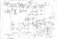
also detunes the PLL to higher frequencies (to reduce power, at startup, etc.) However, just to be safe, I think it'd be best to still design/build the inverter in such a way that even if frequency is lower than resonant frequency, the switchers still won't be overloaded - i.e. freewheel diodes and 'series' diodes to isolate the MOSFET intrinsic body diode. It may be redundant, but I like belt-and-braces security, so to speak.
Another question though: on your website, you say: "The body-diode is isolated by means of a Schottky Barrier diode connected in series with the MOSFET drain lead. (Schottky diodes operate due to majority carrier conduction, and therefore do not exhibit any significant reverse recovery time. Essentially, they turn off immediately when the current tries to change direction.)"
My question: *must* the series diode be a Schottky diode? Or can it be a plain (fast-recovery) diode too?
This part isn't entirely clear to me yet.
If it must be Schottky, I'll use MBR1545's (have a bunch of them out of PC PSUs; 15A, 45V max, TO220 so can be easily mounted on a cooling fin, though I'm not sure they need the cooling; but I'd rather overbuild than run risks of overloading components)
Interesting remarks on the dead-time too.... I thought more deadtime would be better; or at least that excess deadtime wouldn't do harm. But apparently it can do harm, in that it may overstress the freewheel diodes. Learned something new there. Very thankful for the time and effort you put into your website - it is very much appreciated.
Peter.
Dinges, Mon Dec 28 2009, 09:08PM
Thanks for the response Richie.
I was just reading this page of your website (http://www.richieburnett.co.uk/sstate3.html); for some reason I hadn't seen this before, but it seemed to perfectly answer my question....
The PLL circuit I intend to use (based on Hernán Gonzalez's design: (warning, 1.8MB file)

also detunes the PLL to higher frequencies (to reduce power, at startup, etc.) However, just to be safe, I think it'd be best to still design/build the inverter in such a way that even if frequency is lower than resonant frequency, the switchers still won't be overloaded - i.e. freewheel diodes and 'series' diodes to isolate the MOSFET intrinsic body diode. It may be redundant, but I like belt-and-braces security, so to speak.
Another question though: on your website, you say: "The body-diode is isolated by means of a Schottky Barrier diode connected in series with the MOSFET drain lead. (Schottky diodes operate due to majority carrier conduction, and therefore do not exhibit any significant reverse recovery time. Essentially, they turn off immediately when the current tries to change direction.)"
My question: *must* the series diode be a Schottky diode? Or can it be a plain (fast-recovery) diode too?
This part isn't entirely clear to me yet.
If it must be Schottky, I'll use MBR1545's (have a bunch of them out of PC PSUs; 15A, 45V max, TO220 so can be easily mounted on a cooling fin, though I'm not sure they need the cooling; but I'd rather overbuild than run risks of overloading components)
Interesting remarks on the dead-time too.... I thought more deadtime would be better; or at least that excess deadtime wouldn't do harm. But apparently it can do harm, in that it may overstress the freewheel diodes. Learned something new there. Very thankful for the time and effort you put into your website - it is very much appreciated.
Peter.
Re: induction heater project - feedback on inverter.
wylie, Wed Dec 30 2009, 04:31AM
Richie, i've reread your IH section many a time. How have i missed those PDFs? Am i just that blind?
I think what he's saying is that the schottkys are even faster. I suppose the only reason to go with the non-schottky fast recovery diodes would be for higher reverse voltage ratings than schottkys can achieve. Or someother Vdrop or capacitance related design choice.
What i'm not clear on is how schottkys can do the job at all. I just don't understand what voltage they see, is it just the drop across the tank/load+spikes? Otherwise i'd think you'd need a diode there with as high a standoff voltage as your FET.
wylie, Wed Dec 30 2009, 04:31AM
Richie, i've reread your IH section many a time. How have i missed those PDFs? Am i just that blind?
My question: *must* the series diode be a Schottky diode? Or can it be a plain (fast-recovery) diode too?
This part isn't entirely clear to me yet
I think what he's saying is that the schottkys are even faster. I suppose the only reason to go with the non-schottky fast recovery diodes would be for higher reverse voltage ratings than schottkys can achieve. Or someother Vdrop or capacitance related design choice.
What i'm not clear on is how schottkys can do the job at all. I just don't understand what voltage they see, is it just the drop across the tank/load+spikes? Otherwise i'd think you'd need a diode there with as high a standoff voltage as your FET.
Re: induction heater project - feedback on inverter.
Sulaiman, Wed Dec 30 2009, 10:10AM
Just a minor change to your schematic, mainly to maximise the electrolytics
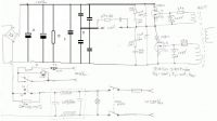
A) are your electrolytics,
since they are rated 400V you can use them in parallel across the DC bus.
B) is a resistor to discharge the DC Bus .. could be 22k
C) is a low impedance film capacitor to bypass the DC Bus at high frequencies
D) are your resonant capacitors.
Your soft-start resistor of 10k seems rather high value,
I'd go for 100R wirewound, 10W or more.
(wirewound resistors have good at short-term overload capability)
Sulaiman, Wed Dec 30 2009, 10:10AM
Just a minor change to your schematic, mainly to maximise the electrolytics

A) are your electrolytics,
since they are rated 400V you can use them in parallel across the DC bus.
B) is a resistor to discharge the DC Bus .. could be 22k
C) is a low impedance film capacitor to bypass the DC Bus at high frequencies
D) are your resonant capacitors.
Your soft-start resistor of 10k seems rather high value,
I'd go for 100R wirewound, 10W or more.
(wirewound resistors have good at short-term overload capability)
Re: induction heater project - feedback on inverter.
IamSmooth, Wed Dec 30 2009, 01:09PM
How important is capacitor C, and what is the consequence of not having one?
IamSmooth, Wed Dec 30 2009, 01:09PM
How important is capacitor C, and what is the consequence of not having one?
Re: induction heater project - feedback on inverter.
GeordieBoy, Wed Dec 30 2009, 02:35PM
Schottky diodes are the best choice for blocking the MOSFET's intrinsic body-drain diode for two reasons:
1. They have a low forward-voltage drop,
2. They have a negligible reverse-recovery time
They only need to be rated for about 30V in the reverse blocking direction. This is because when current is in the direction where the Schottky's are reverse biases, the external Fast-recovery free-wheel diode is in conduction. Theoretically the Schottky diodes only need to be able to reverse block up to the forward conduction voltage of the FRED. This means you can use low-voltage Schottky diodes and minimise conduction losses. In practice 30V is a good comprimise for the Schottky diodes since they will see a small voltage spike in addition to the FRED voltage drop as the Free-wheel diodes start to pick up the load current. (The fast recovery free-wheel diodes need to be rated for the full DC bus voltage plus a safety margin however. So until recently these needed to be ultra-fast Silicon Rectifier diodes, however SiC Schottkys with high-voltage ratings are now becoming cheaper.
-Richie,
Re: induction heater project - feedback on inverter.
Dinges, Wed Dec 30 2009, 06:31PM
Thanks for your comments, Sulaiman and Richie. I have taken note. Have used Schottky diodes (MBRB2545; 25A; 45V) as the series diode (mounted on the same heatsink as the IRFP460; was possible because the cathode of the diodes connects to the tab of the TO220 case, and the drain of the IRFP460 is also connected to the tab of the TO247 case; drain and diode cathode can thus be mounted on the same heatsink, without needing insulation).
The freewheel diodes (HFA15TB60; 15A; 600V; ultrafast, 42ns, TO220 case) have been mounted on their own small heatsink. The end result is that the MOSFET's intrinsic body diodes will be totally isolated.
Sulaiman, have taken note of your modifications too. I admit the softstart resistor seems much too high, will go down to 220 ohm. Will follow your advice on the capacitors too.
BTW, I noticed you eliminated the series capacitor (4*220n); what was your rationale behind this? Don't you think it would be advisory to include it?
Peter.
Re: induction heater project - feedback on inverter.
IamSmooth, Wed Dec 30 2009, 07:33PM
Richie, how adequate are the MUR4100s for the freewheelers?
IamSmooth, Wed Dec 30 2009, 07:33PM
Richie, how adequate are the MUR4100s for the freewheelers?
Re: induction heater project - feedback on inverter.
wylie, Wed Dec 30 2009, 10:52PM
D'oh, that's the part i was missing.
Rock on Richie!
wylie, Wed Dec 30 2009, 10:52PM
This is because when current is in the direction where the Schottky's are reverse biases, the external Fast-recovery free-wheel diode is in conduction.
D'oh, that's the part i was missing.
Rock on Richie!
Re: induction heater project - feedback on inverter.
Dinges, Tue Jan 12 2010, 06:32PM
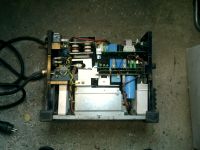
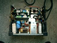
As I was at my favourite hardware store the other day (which also happens to have a welding machine repair dept. in-house) I tried my luck.... explained what I did (hobby electronics, needing parts (in my case, large ferrite cores) for a DIY induction heater) and that these were usually inside welding inverters. Asked if they were throwing an unrepairable machine away that I might gut for parts.
5 minutes later, Peter walked out a happy man.... with 4 large welding inverters under his arm.
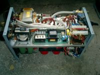
(also note the RF HV arcstarter in the middle/front left)
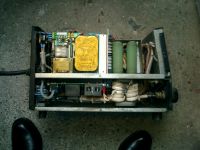
(another arcstarter in there too)
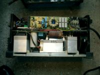
And I'm particularly happy with this cute little Kemppi MasterTIG 1500 inverter (230Vac, not three-phase 400Vac like the other machines):
Had a bit of a chat with the guy who runs the repair department, which was interesting. As was to be expected, they don't repair at component level but simply replace modules.
The loot: large 3-phase rectifiers (ISOTOP case), large cooling fins, big MOSFETs, big thyristors (SCRs), gate-drive transformers for same, a few huge caps, gas solenoids (another thing the doctor ordered for the microTIG), large rectifier diodes screwed into even larger heatsinks, etc.etc.
There are also two RF-HV generators in there, with Tungsten spark gap... basically meaning my original experiments (using a ferrite rod and DIY HV generator and make-shift spark gap) were needless, as I've now got the professional thing right here in my hands, including the large ferrite cores to couple it into.
I couldn't help but smile as I saw 1890s-technology (tungsten spark gap) in a machine from 1999, which otherwise consisted of fancy power semiconductors and a microprocessor to control it all....
Those inverters are veritable gold mines of parts.
Peter.
Dinges, Tue Jan 12 2010, 06:32PM
As I was at my favourite hardware store the other day (which also happens to have a welding machine repair dept. in-house) I tried my luck.... explained what I did (hobby electronics, needing parts (in my case, large ferrite cores) for a DIY induction heater) and that these were usually inside welding inverters. Asked if they were throwing an unrepairable machine away that I might gut for parts.
5 minutes later, Peter walked out a happy man.... with 4 large welding inverters under his arm.

(also note the RF HV arcstarter in the middle/front left)

(another arcstarter in there too)

And I'm particularly happy with this cute little Kemppi MasterTIG 1500 inverter (230Vac, not three-phase 400Vac like the other machines):


Had a bit of a chat with the guy who runs the repair department, which was interesting. As was to be expected, they don't repair at component level but simply replace modules.
The loot: large 3-phase rectifiers (ISOTOP case), large cooling fins, big MOSFETs, big thyristors (SCRs), gate-drive transformers for same, a few huge caps, gas solenoids (another thing the doctor ordered for the microTIG), large rectifier diodes screwed into even larger heatsinks, etc.etc.
There are also two RF-HV generators in there, with Tungsten spark gap... basically meaning my original experiments (using a ferrite rod and DIY HV generator and make-shift spark gap) were needless, as I've now got the professional thing right here in my hands, including the large ferrite cores to couple it into.
I couldn't help but smile as I saw 1890s-technology (tungsten spark gap) in a machine from 1999, which otherwise consisted of fancy power semiconductors and a microprocessor to control it all....
Those inverters are veritable gold mines of parts.
Peter.
Re: induction heater project - feedback on inverter.
Steve Conner, Tue Jan 12 2010, 09:44PM
Indeed they are! Or "OMG inverter pr0n" as our younger members might say.
I'm also surprised to see Tesla's old spark gap in there. It should be possible to make a solid-state arcstarter using similar principles to the DRSSTC, OLTC, SISG or what have you, and I half expected that welder manufacturers would have done that. But maybe they decided it wasn't worth the extra cost and complexity.
Re: induction heater project - feedback on inverter.
GeordieBoy, Wed Jan 13 2010, 10:17AM
> I'm also surprised to see Tesla's old spark gap in there...
I too am very surprised! That old Tesla circuit with the multiple series spark gaps generates a horrendous amount of EMI, that can (and probably DOES) leave the welding box as radiated and conducted emissions. So from an approvals point of view I would have thought that any nice clean solid-state solution would make things a lot easier!
Are the inverters UL or CE marked?
-Richie,
Re: induction heater project - feedback on inverter.
Steve Conner, Wed Jan 13 2010, 11:01AM
Those "conducted emissions" are the very thing needed to start the welding arc
I imagine there must be an EMI exemption for welders. Also, the coupling core is hopefully a power ferrite grade that will be very lossy at VHF, so that should help.
Steve Conner, Wed Jan 13 2010, 11:01AM
GeordieBoy wrote ...
That old Tesla circuit with the multiple series spark gaps generates a horrendous amount of EMI, that can (and probably DOES) leave the welding box as radiated and conducted emissions.
That old Tesla circuit with the multiple series spark gaps generates a horrendous amount of EMI, that can (and probably DOES) leave the welding box as radiated and conducted emissions.
Those "conducted emissions" are the very thing needed to start the welding arc

I imagine there must be an EMI exemption for welders. Also, the coupling core is hopefully a power ferrite grade that will be very lossy at VHF, so that should help.
Re: induction heater project - feedback on inverter.
Dinges, Wed Jan 13 2010, 11:34PM
The Kemppi uses a RF arcstarter circuit without sparkgap - haven't figured out exactly how it works. I'm trying to repair the Kemppi for personal use.
As to welders being exempt from EMI requirements.... could very well be. What I do know is that every manual of inverter welders that I'm familiar with clearly states to *not* use it in 'sensitive' environments, such as workshops with CNC machines or in hospitals, but to use 'lift arc' starting in those situations.
Normally, the RF arcstarting is only used for a short time, just before the 'start weld' button is pushed and the arc is struck. All machines I'm familiar with turn off the RF arc start if an arc hasn't been struck within 1-4 seconds, limiting on-time of the RF HV generator.
Of course, there are also welding machines where you have the option to have RF HV permanently on....
Peter.
Dinges, Wed Jan 13 2010, 11:34PM
The Kemppi uses a RF arcstarter circuit without sparkgap - haven't figured out exactly how it works. I'm trying to repair the Kemppi for personal use.
As to welders being exempt from EMI requirements.... could very well be. What I do know is that every manual of inverter welders that I'm familiar with clearly states to *not* use it in 'sensitive' environments, such as workshops with CNC machines or in hospitals, but to use 'lift arc' starting in those situations.
Normally, the RF arcstarting is only used for a short time, just before the 'start weld' button is pushed and the arc is struck. All machines I'm familiar with turn off the RF arc start if an arc hasn't been struck within 1-4 seconds, limiting on-time of the RF HV generator.
Of course, there are also welding machines where you have the option to have RF HV permanently on....

Peter.
Re: induction heater project - feedback on inverter.
Dinges, Thu Jan 14 2010, 12:04AM
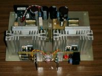
Work on the 1kW induction heater has been progressing steadily. Below an image of the inverter, with the driver board.
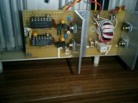
Close-up of the driver board:
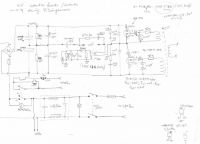
The schematic of the inverter:
Schematic of the driver:
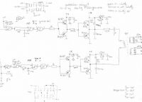
(final changes to the driver, not yet corrected in the schematic: the 100 ohm resistor has been exchanged for a 220 ohm one, the 1k resistors to the base of the BC547/557 have been increased to 6k8, and the 4.7 ohm gate resistors have been removed)
Did a first test, with a work coil and tank capacitor array I still had lying about, resonant at about 200 kHz. Used the function generator to provide a signal to the drive board.
Cranked power up (turning up the variac) till 130W. The workpiece, an M8 bolt, became quite hot (estimated 350 deg.C). Unfortunately, and as was to be expected, the powdered-iron toroid I was still using got quite hot too, so I didn't dare to go higher than 130W input power. Next task is making a proper tank circuit with decent coupling transformer.
The inverter current sampling circuit works fine, but had an insanely large time constant, so the 470k resistor was replaced by a 4k7 one, making it respond much less sluggishly to changes in inverter current.
Below are images of the scoped waveshape at the gate of the FETs. It's much slower than I'd hoped for, about 800ns rise time; I think this is excessive for a 100kHz induction heater?
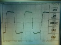
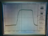
Removing the 4.7 ohm gate resistors decreased the risetime a little, by about 100ns (it was originally 900ns). Removing the resistor in the primary of the gatedrive transformer didn't speed the circuit up, but greatly distorted the waveshape, so that resistor was left in place.
Inductance of the GDT is about 600uH, the leakage inductance 0.3uH.
Now putting the last hand on the PLL controller board, mostly based on the work by Hernán González with some small modifications.
All comments, advice, corrections, etc. welcome.
More pictures and information here: http://picasaweb.google.com/motorconversion/Induction_heater#
Peter.
Dinges, Thu Jan 14 2010, 12:04AM
Work on the 1kW induction heater has been progressing steadily. Below an image of the inverter, with the driver board.

Close-up of the driver board:

The schematic of the inverter:

Schematic of the driver:

(final changes to the driver, not yet corrected in the schematic: the 100 ohm resistor has been exchanged for a 220 ohm one, the 1k resistors to the base of the BC547/557 have been increased to 6k8, and the 4.7 ohm gate resistors have been removed)
Did a first test, with a work coil and tank capacitor array I still had lying about, resonant at about 200 kHz. Used the function generator to provide a signal to the drive board.
Cranked power up (turning up the variac) till 130W. The workpiece, an M8 bolt, became quite hot (estimated 350 deg.C). Unfortunately, and as was to be expected, the powdered-iron toroid I was still using got quite hot too, so I didn't dare to go higher than 130W input power. Next task is making a proper tank circuit with decent coupling transformer.
The inverter current sampling circuit works fine, but had an insanely large time constant, so the 470k resistor was replaced by a 4k7 one, making it respond much less sluggishly to changes in inverter current.
Below are images of the scoped waveshape at the gate of the FETs. It's much slower than I'd hoped for, about 800ns rise time; I think this is excessive for a 100kHz induction heater?


Removing the 4.7 ohm gate resistors decreased the risetime a little, by about 100ns (it was originally 900ns). Removing the resistor in the primary of the gatedrive transformer didn't speed the circuit up, but greatly distorted the waveshape, so that resistor was left in place.
Inductance of the GDT is about 600uH, the leakage inductance 0.3uH.
Now putting the last hand on the PLL controller board, mostly based on the work by Hernán González with some small modifications.
All comments, advice, corrections, etc. welcome.
More pictures and information here: http://picasaweb.google.com/motorconversion/Induction_heater#
Peter.
Re: induction heater project - feedback on inverter.
GeordieBoy, Thu Jan 14 2010, 11:10AM
The gate drive slopes do look a bit slow, and there is no hint of overshoot or ringing, so you should be able to speed them up considerably if you wanted to.
However, the inverter in a typical induction heater operates in a zero-voltage switching mode anyway. You may find that increasing the slew-rate of the gate-drive signals doesn't give much reduction in device temperatures. Even with slow gate-drive slopes the switching losses when operated in ZVS can be suprisingly low.
If you want to speed up the gate-drive slopes I would recommend looking at dedicated MOS gate-drive IC's like Microchip/Temic TC4421/TC4422 or the UCC things that everyone on here seems to use. I'd also loose the ferrite-beads on the gates unless they were put there to solve a particular EMI problem. (Often EMI requirements and efficiency requirements are totally contradictory. i.e. Slug the gate-drive and slow down switching edges for reduced EMI, _OR_ speed up gate-drive slope and switch in the minimum time for maximum efficiency. Somewhere in the middle there is usually an acceptable solution!)
-Richie,
Re: induction heater project - feedback on inverter.
Dinges, Wed Jan 20 2010, 11:52AM
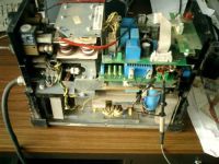
Just had a chance to have a quick look at that Kemppi welding machine to see what might be wrong with it. Had already taken out the control boards and tested all the electrolytics and power supply voltages - all were fine. Wound a single-turn test winding over the gate-drive transformer for the thyristor to connect a scope to; re-installed the board and turned the machine on.
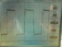
Perfect pulses on the scope, so it appears the thyristor is getting a drive signal. That rules out just about all of the control electronics as possible fault factors (note pulse is maximum width, but that's to be expected as no output current flows, so no current feedback to close the loop and regulate pulse width back to the set value)
Then I tried to figure out where the various power components were. But before doing so, just to be sure, decided to short the outputs of the transistor with a large screwdriver (= shorting the electrolytic caps). Shorting the caps gave major sparks.... So looks like DC input is there as well.
That seems to strongly indicate a defect thyristor block. Trouble is, to get at it (or any other part), the machine needs to be taken nearly completely apart (the downside of a small, compact machine....). And very hard to test-run it when taken apart. But everything so far seems to strongly indicate a defect thyristor brick, which means it's probably a simple repair. Strange though, I didn't expect thyristors to fail open (i.e. infinite resistance). Not sure I have a suitable replacement - only spare thyristor brick I have is 55A/800V, and is physically smaller than the original one. The thyristor bricks in the other 3-phase machines were all much larger.
Funny though - it's basically an overgrown PC PSU, at 1500W. Half-bridge design, using two large thyristors (in one brick). 2 electrolytic capacitors, the usual series capacitors to the transformer, and 2 flywheel diodes (will have to check those too).
If the control board would've been dead and unrepairable, I think I'd have replaced it with a TL494 hack.
May take a while before I get some more time & chance to have a closer look at it.
Peter.
Dinges, Wed Jan 20 2010, 11:52AM
Just had a chance to have a quick look at that Kemppi welding machine to see what might be wrong with it. Had already taken out the control boards and tested all the electrolytics and power supply voltages - all were fine. Wound a single-turn test winding over the gate-drive transformer for the thyristor to connect a scope to; re-installed the board and turned the machine on.


Perfect pulses on the scope, so it appears the thyristor is getting a drive signal. That rules out just about all of the control electronics as possible fault factors (note pulse is maximum width, but that's to be expected as no output current flows, so no current feedback to close the loop and regulate pulse width back to the set value)
Then I tried to figure out where the various power components were. But before doing so, just to be sure, decided to short the outputs of the transistor with a large screwdriver (= shorting the electrolytic caps). Shorting the caps gave major sparks.... So looks like DC input is there as well.
That seems to strongly indicate a defect thyristor block. Trouble is, to get at it (or any other part), the machine needs to be taken nearly completely apart (the downside of a small, compact machine....). And very hard to test-run it when taken apart. But everything so far seems to strongly indicate a defect thyristor brick, which means it's probably a simple repair. Strange though, I didn't expect thyristors to fail open (i.e. infinite resistance). Not sure I have a suitable replacement - only spare thyristor brick I have is 55A/800V, and is physically smaller than the original one. The thyristor bricks in the other 3-phase machines were all much larger.
Funny though - it's basically an overgrown PC PSU, at 1500W. Half-bridge design, using two large thyristors (in one brick). 2 electrolytic capacitors, the usual series capacitors to the transformer, and 2 flywheel diodes (will have to check those too).
If the control board would've been dead and unrepairable, I think I'd have replaced it with a TL494 hack.
May take a while before I get some more time & chance to have a closer look at it.
Peter.
Re: induction heater project - feedback on inverter.
IamSmooth, Wed Jan 20 2010, 01:43PM
Peter,
What are you using to control the power into the inverter? Is it a variac? If so, what are its specifications?
IamSmooth, Wed Jan 20 2010, 01:43PM
Peter,
What are you using to control the power into the inverter? Is it a variac? If so, what are its specifications?
Re: induction heater project - feedback on inverter.
Dinges, Wed Jan 20 2010, 05:25PM
With the induction heater, I'm using a variac plus an insulation transformer. The insulation transformer is only good for 250W, the variac is a 220V input, 0-260V output (@3.15A), also undersized for this application.
Have just scrounged a case to build the induction heater into, an old Compaq mini-tower. After removing some internal metal parts, it's now an empty box. All that needs to be done is to make a new front cover out of aluminium.
My previous reply is not an induction heater though, but a welding machine I was given and that I'm trying to repair, instead of gutting it for parts. And a correction is in order - there are no thyristors in it, it's controlled by a 75A/600V/350W IGBT brick which is defect, unfortunately.
Peter.
Dinges, Wed Jan 20 2010, 05:25PM
With the induction heater, I'm using a variac plus an insulation transformer. The insulation transformer is only good for 250W, the variac is a 220V input, 0-260V output (@3.15A), also undersized for this application.
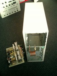
Have just scrounged a case to build the induction heater into, an old Compaq mini-tower. After removing some internal metal parts, it's now an empty box. All that needs to be done is to make a new front cover out of aluminium.

My previous reply is not an induction heater though, but a welding machine I was given and that I'm trying to repair, instead of gutting it for parts. And a correction is in order - there are no thyristors in it, it's controlled by a 75A/600V/350W IGBT brick which is defect, unfortunately.
Peter.
Re: induction heater project - feedback on inverter.
Tonskulus, Wed Jan 20 2010, 08:04PM
Dinges, you stole my idea about using PC tower for induction heater :D
Tonskulus, Wed Jan 20 2010, 08:04PM
Dinges, you stole my idea about using PC tower for induction heater :D
Re: induction heater project - feedback on inverter.
Dinges, Tue Jan 26 2010, 08:09PM
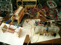
I have just run a few tests using the induction heater inverter and the now nearly-finished tank circuit. The tank consists of 6 turns of 8mm copper pipe and has an inductance of 0.53 uH; the capacitor bank is 2.51uF/440Vac. Resonant frequency is 138 kHz.
So far I've turned input power up to about 500W, using a variac to increase input voltage. The problem:
Everything works fine as long as the workpiece is not yet glowing red hot. Input power is small (I'm using a conservative 200W, as the coupling transformer is still underdimensioned), inverter current about 2A, cooling fins of the FETs stay cold as ice. No detectable temperature rise, neither in the coupling transformer (I'm using a bigger, better one than the single toroid in the image above - that one got pretty hot at 200W, despite being ferrite (of unknown properties, most likely for RFI suppression, so far from ideal))
But when the workpiece reaches a dull-red temperature, inverter current begins to rise rapidly - seems almost like a runaway process. (edit: just noticed that tank voltage rises dramatically too, as well as input power). In the first instance it happened, input power soared to slightly over 1kW over about 10-15 seconds and inverter current went up to over 30A. Both FETs (IRFP460) blew. Have since replaced them, but every time the workpiece reaches glowing temperatures, inverter current rises. I now re-adjust the variac to a lower voltage when that happens, to keep inverter current at about 2A and input power at about 200W.
I know that when a workpiece reaches the Curie temperature, hysteresis losses disappear and we're only left with eddy current losses. However, I had never expected the difference to be *so* dramatic - from 2A to over 30A of current.... Seems like the inverter is nearly running unloaded when the workpiece becomes red hot, to cause such a dramatic rise in current?
My question: is this normal, expected behaviour? Especially the degree of current rise. What can I do to keep input power reasonable? Add more turns to the transformer? Permanently lower input voltage? (which lowers output power, so means it takes longer to reach a certain temperature). Add more load?
What I want is the workpiece to get hotter than 'red hot' - white hot. But it seems the inverter starts to protest and absorb all the power in the zone between a red hot and white hot workpiece?
Note that at the moment I'm still running a test-setup, not using the PLL controller board. I first want to get a feeling for how it all behaves, before I control the inverter automatically. The inverter is now powered via a variac, and input signal generated with a function generator, whilst monitoring tank voltage on the scope, and input power with a 'kill-a-watt' meter. The PLL controller board has an inverter over-current safety, which shuts off the inverter when inverter current rises above a set limit. So the inverter is protected, but it's not really controlling inverter current.
Unrelated: one other thing that was very noticeable was that when frequency is just below, or exactly at resonance, there are some nasty spikes on the tank voltage waveshape. Adjusting frequency to slightly above resonance makes that disappear and produces a nice clean sine waveshape, though at a slightly smaller amplitude than when at 'full' resonance (I estimate about 3-4% less tank voltage). This seems to confirm what Richie Burnett writes on his website, that ideally you want the inverter to run a tad above resonant frequency for clean switching.
Peter.
Dinges, Tue Jan 26 2010, 08:09PM
I have just run a few tests using the induction heater inverter and the now nearly-finished tank circuit. The tank consists of 6 turns of 8mm copper pipe and has an inductance of 0.53 uH; the capacitor bank is 2.51uF/440Vac. Resonant frequency is 138 kHz.

So far I've turned input power up to about 500W, using a variac to increase input voltage. The problem:
Everything works fine as long as the workpiece is not yet glowing red hot. Input power is small (I'm using a conservative 200W, as the coupling transformer is still underdimensioned), inverter current about 2A, cooling fins of the FETs stay cold as ice. No detectable temperature rise, neither in the coupling transformer (I'm using a bigger, better one than the single toroid in the image above - that one got pretty hot at 200W, despite being ferrite (of unknown properties, most likely for RFI suppression, so far from ideal))
But when the workpiece reaches a dull-red temperature, inverter current begins to rise rapidly - seems almost like a runaway process. (edit: just noticed that tank voltage rises dramatically too, as well as input power). In the first instance it happened, input power soared to slightly over 1kW over about 10-15 seconds and inverter current went up to over 30A. Both FETs (IRFP460) blew. Have since replaced them, but every time the workpiece reaches glowing temperatures, inverter current rises. I now re-adjust the variac to a lower voltage when that happens, to keep inverter current at about 2A and input power at about 200W.
I know that when a workpiece reaches the Curie temperature, hysteresis losses disappear and we're only left with eddy current losses. However, I had never expected the difference to be *so* dramatic - from 2A to over 30A of current.... Seems like the inverter is nearly running unloaded when the workpiece becomes red hot, to cause such a dramatic rise in current?
My question: is this normal, expected behaviour? Especially the degree of current rise. What can I do to keep input power reasonable? Add more turns to the transformer? Permanently lower input voltage? (which lowers output power, so means it takes longer to reach a certain temperature). Add more load?
What I want is the workpiece to get hotter than 'red hot' - white hot. But it seems the inverter starts to protest and absorb all the power in the zone between a red hot and white hot workpiece?
Note that at the moment I'm still running a test-setup, not using the PLL controller board. I first want to get a feeling for how it all behaves, before I control the inverter automatically. The inverter is now powered via a variac, and input signal generated with a function generator, whilst monitoring tank voltage on the scope, and input power with a 'kill-a-watt' meter. The PLL controller board has an inverter over-current safety, which shuts off the inverter when inverter current rises above a set limit. So the inverter is protected, but it's not really controlling inverter current.
Unrelated: one other thing that was very noticeable was that when frequency is just below, or exactly at resonance, there are some nasty spikes on the tank voltage waveshape. Adjusting frequency to slightly above resonance makes that disappear and produces a nice clean sine waveshape, though at a slightly smaller amplitude than when at 'full' resonance (I estimate about 3-4% less tank voltage). This seems to confirm what Richie Burnett writes on his website, that ideally you want the inverter to run a tad above resonant frequency for clean switching.
Peter.
Re: induction heater project - feedback on inverter.
Tonskulus, Tue Jan 26 2010, 09:29PM
Dinges: Have u tested that system totally unloaded so that there is no "secondary" through the toroid transformer?
Maybe there really is not enough primary turns and it saturates. Without secondary, input current should be very low.
Tonskulus, Tue Jan 26 2010, 09:29PM
Dinges: Have u tested that system totally unloaded so that there is no "secondary" through the toroid transformer?
Maybe there really is not enough primary turns and it saturates. Without secondary, input current should be very low.
Re: induction heater project - feedback on inverter.
IamSmooth, Wed Jan 27 2010, 02:35AM
When you get the steel glowing hot the current will start to go up. The resonant frequency will also change, so you will need to make sure you stay above the frequency. Monitor the inverter voltage and the inverter current, making sure they are in phase, or at least have the current lagging.
Re: induction heater project - feedback on inverter.
GeordieBoy, Thu Jan 28 2010, 12:25PM
When iron goes through it's Curie temperature it looses its magnetic properties. Therefore one of the loss factors involved in the induction heating process (the hysteresis loss component) drops out of the equation.
This decrease in energy loss raises the Q of a series resonant tank circuit. And as a result of the higher Q the current drawn from the inverter goes up.
As you spotted the inverter will operate quite happily when tuned to any frequency higher than the natural frequency of the series resonant tank circuit, except real power throughput diminishes away from resonance. (Only on the low-frequency side of resonance does the tank look capacitive and forced reverse-recovery of the FWDs causes those nasty spikes and EMI that gets EVERYWHERE!)
The easiest way to keep the inverter current under control when the tank Q rises, is to tune the inverter to a slightly higher frequency. The high Q of the tank circuit means that the phase angle of the load current changes quickly for a small change in f, so you won't need to detune much for the active power contribution to decrease back to something more reasonable. (The slight lagging PF of the load current is actually a good thing as it helps to commutate the devices in the inverter during the switch's dead-times.)
-Richie,
Re: induction heater project - feedback on inverter.
Dinges, Thu Jan 28 2010, 07:30PM
Thanks for the responses, all.
As I'm still driving the inverter manually (using a variac and function generator), I'm beginning to learn how it behaves. Indeed, when the workpiece starts to glow inverter current rises, and so does input power and tank voltage. When it starts to rise I back off the variac to keep input power constant at about 600W (600W is what it normally draws, at 230V, with the present amount of turns on the coupling transformer, but it's capable of 1000W continuous without anything overheating).
I'm amazed how quickly it heats a workpiece to red hot, even at limited power; just tried a 12mm rod of steel - after 50-80 seconds it's red hot. The amount of energy it takes is only about 0.01 kWh, or 10 Wh.
Am still running it without watercooling, but even at 500-600W for more than a minute, the working coil gets very hot. Part of this is no doubt because of radiated heat from the glowing workpiece. I will add watercooling to the machine too, wich is needed, even at that relatively small (for an induction heater) power. My intention is to adjust it, when finished, to a maximum power of 750W (the inverter cooling fins remain cold, btw, as do the 3 powdered-iron toroids (yellow/white)).
I had already finished building the PLL controller (Hernán González's design, with modifications) but it doesn't seem to lock onto the tank resonant frequency. I'm still debugging the board but having good hopes of getting it working; I'm now suspecting the LM393s introduce too much phaseshift between their inputs and outputs, at 138 kHz, and one of them is oscillating at about 40 kHz. And there are some other things to test for. When using this PLL, it will automatically detune the VCO to a higher frequency as tank voltage increases beyond the set value, so that means no more manually backing the variac off.
Here's the obligatory picture of a glowing piece of steel:
In other news.... I managed to get the Kemppi welding inverter working again. The IGBT brick was defect. Checked the gate drive but that was fine (no spikes >20V that might damage the IGBT), so I ordered a similar IGBT brick (which was cheaper than I had initially feared) and the machine works again. Very nice machine, with a smooth and stable arc. And can't beat the cost.
Peter.
Dinges, Thu Jan 28 2010, 07:30PM
Thanks for the responses, all.
As I'm still driving the inverter manually (using a variac and function generator), I'm beginning to learn how it behaves. Indeed, when the workpiece starts to glow inverter current rises, and so does input power and tank voltage. When it starts to rise I back off the variac to keep input power constant at about 600W (600W is what it normally draws, at 230V, with the present amount of turns on the coupling transformer, but it's capable of 1000W continuous without anything overheating).
I'm amazed how quickly it heats a workpiece to red hot, even at limited power; just tried a 12mm rod of steel - after 50-80 seconds it's red hot. The amount of energy it takes is only about 0.01 kWh, or 10 Wh.
Am still running it without watercooling, but even at 500-600W for more than a minute, the working coil gets very hot. Part of this is no doubt because of radiated heat from the glowing workpiece. I will add watercooling to the machine too, wich is needed, even at that relatively small (for an induction heater) power. My intention is to adjust it, when finished, to a maximum power of 750W (the inverter cooling fins remain cold, btw, as do the 3 powdered-iron toroids (yellow/white)).
I had already finished building the PLL controller (Hernán González's design, with modifications) but it doesn't seem to lock onto the tank resonant frequency. I'm still debugging the board but having good hopes of getting it working; I'm now suspecting the LM393s introduce too much phaseshift between their inputs and outputs, at 138 kHz, and one of them is oscillating at about 40 kHz. And there are some other things to test for. When using this PLL, it will automatically detune the VCO to a higher frequency as tank voltage increases beyond the set value, so that means no more manually backing the variac off.
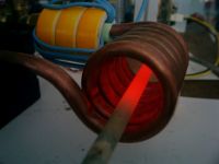
Here's the obligatory picture of a glowing piece of steel:

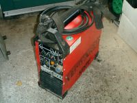
In other news.... I managed to get the Kemppi welding inverter working again. The IGBT brick was defect. Checked the gate drive but that was fine (no spikes >20V that might damage the IGBT), so I ordered a similar IGBT brick (which was cheaper than I had initially feared) and the machine works again. Very nice machine, with a smooth and stable arc. And can't beat the cost.


Peter.
Re: induction heater project - feedback on inverter.
Dinges, Sun Jan 31 2010, 07:15PM
Succes at last!
After messing about with the induction heater's control board for 3 evenings and one full day, it seems to finally be working properly now. After many hours messing with comparators that preferred to oscillate rather than compare, comparators that saw up to -15V input whereas they can't take more than -0.3V, leakage currents due to solder flux that messed everything up, phase-errors introduced by too long transit times in NAND-inverters, etc.etc, and a reversed diode that prevented the loop filter's control signal from ever reaching the voltage controlled oscillator , most major bugs seem to have been ironed out finally.
So now it's possible to run the induction heater 'automatically', i.e. without needing to tune for resonance manually, or adjusting the variac to prevent magic smoke escaping: the PLL now tunes for exact resonance and the tank over-voltage protection kicks in when it gets above about 60V, protecting the inverter from too high loads and running unloaded. And the turn-on sequence doesn't matter, i.e whether you first turn on the PLL and then the inverter, or otherwise - nothing blows. That's good.
To satisfy the visual aspect, here's a picture of the workbench. Somewhere in that mess there's a working induction heater.
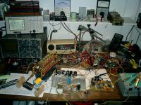
To the left the tank circuit, with workpiece in it (hard to see, but glowing red-hot as 850W of RF is being pushed into it). It's still working off the variac, but more as a precaution to quickly reduce voltage if needed - it's now continuously working on 230Vac.
The scope above shows the waveshape - perfectly locked onto the resonant frequency (which varies, depending on the size of the load, i.e. workpiece, and temperature it has). Amplitude is about 60Vac, which means that about 130A of current circulates in the tank circuit. And that shows: the 8mm copper pipes get *hot*, the workcoil gets scorching hot, and the capacitors get warm (about 50 deg. C) after a while. Not surprizing, as each has to handle about 7.5A at 140kHz... So watercooling is most definitely not a luxury, not even at this relatively low power level of 850W, not if you want to run it for more than a few minutes at a time. Have pushed output power up to 1000W without problems, but don't want to get much higher because of the capacitorbank that's becoming the limiting factor
The analog meter to the above-right of the scope shows the tank voltage as measured by the controller, about 60V. Nice to have an analog display of tank voltage, and see how it rises as the workpiece starts to glow, after which over-voltage limit kicks in and reduces power to a safe 150W.
The yellow/white powdered iron toroids transfer the energy from the inverter to the tank circuit. Primary contains 14 turns of wire (still have to optimize this part; less turns may be a possibility, without the inverter protesting). Toroids stay cool, to my surprize, so will use these in the final construction too.
To the right of the tank circuit, the inverter - a half bridge with 2 MTW14N50E 's (I ran out of IRFP460s.... though all blew while I was still driving it manually - under automatic control, nothing unexpected happens, due to the inverter current limit and tank voltage limits). The cooling fins of the FETs stay cool, don't get above 35C even after extended running at 850W, so that's good too.
To the right of the inverter is the PLL control circuit. Contains its own 15V regulated power supply. A 4046 takes care of the PLL/VCO business. Various comparators do the signal processing and provide some security features, to protect against tank overvoltage and inverter overcurrent. When an error is triggered, power gets reduced to a safe level by detuning the VCO to a higher frequency (thus limiting power throughput) and lighting a LED (and in the final build, buzzing a buzzer). After resetting the error (preferrably after setting the power-control potmeter a tad lower), it starts locking and heating at full (set) power again.
The DMM at the top-right indicates the VCO input voltage, which determines the VCO's frequency. Should be somewhere between 1-14V, preferably being at the mid-point, 7V, but at 6V it's close enough for the moment, as there's still plenty of headroom to regulate below and above the resonant frequency.
To the right of the PLL, the infamous Oztules PC PSU, which provides all the power for the control board and gatedriver, at 24V.
And this is what all that fancy electronics does....
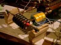
Looks much the same as the image of a glowing steel rod a few posts before, only this time it does it all automatically - just press the start button, and press stop when finished.
Tried out whether I could get a workpiece hot enough for brazing - alas, didn't work. It's getting close, but not there quite yet. 850W isn't much power either. But I don't want to push this machine much higher, we'll save that for the follow-up project (which will use a ready-made 7.2kVA full-bridge inverter; as I can't draw more than 3700W from single-phase grid anyway, that seems sturdy enough).
That's it - long writeup, but not nearly as long as it took to get it into its present working state. Next task is to debug the last errors (esp. inverter current error latching circuit) and then start building it into its cabinet, an old PC mini-tower.
Many thanks go to forum member Hernán González, to whom much of the control circuitry is attributed. I added some improvements and modifications myself (and weeded out a few errors in the design too), NeonJohn for the idea of the series topology and generally excellent website, and Iamsmooth for his induction heater tutorial. Especially the explanations on the working of a PLL were valuable to me.
And of course all the forum members for their input, ideas and comments - Thanks!
Peter.
Dinges, Sun Jan 31 2010, 07:15PM
Succes at last!
After messing about with the induction heater's control board for 3 evenings and one full day, it seems to finally be working properly now. After many hours messing with comparators that preferred to oscillate rather than compare, comparators that saw up to -15V input whereas they can't take more than -0.3V, leakage currents due to solder flux that messed everything up, phase-errors introduced by too long transit times in NAND-inverters, etc.etc, and a reversed diode that prevented the loop filter's control signal from ever reaching the voltage controlled oscillator
 , most major bugs seem to have been ironed out finally.
 So now it's possible to run the induction heater 'automatically', i.e. without needing to tune for resonance manually, or adjusting the variac to prevent magic smoke escaping: the PLL now tunes for exact resonance and the tank over-voltage protection kicks in when it gets above about 60V, protecting the inverter from too high loads and running unloaded. And the turn-on sequence doesn't matter, i.e whether you first turn on the PLL and then the inverter, or otherwise - nothing blows. That's good.
To satisfy the visual aspect, here's a picture of the workbench. Somewhere in that mess there's a working induction heater.

To the left the tank circuit, with workpiece in it (hard to see, but glowing red-hot as 850W of RF is being pushed into it). It's still working off the variac, but more as a precaution to quickly reduce voltage if needed - it's now continuously working on 230Vac.
The scope above shows the waveshape - perfectly locked onto the resonant frequency (which varies, depending on the size of the load, i.e. workpiece, and temperature it has). Amplitude is about 60Vac, which means that about 130A of current circulates in the tank circuit. And that shows: the 8mm copper pipes get *hot*, the workcoil gets scorching hot, and the capacitors get warm (about 50 deg. C) after a while. Not surprizing, as each has to handle about 7.5A at 140kHz... So watercooling is most definitely not a luxury, not even at this relatively low power level of 850W, not if you want to run it for more than a few minutes at a time. Have pushed output power up to 1000W without problems, but don't want to get much higher because of the capacitorbank that's becoming the limiting factor
The analog meter to the above-right of the scope shows the tank voltage as measured by the controller, about 60V. Nice to have an analog display of tank voltage, and see how it rises as the workpiece starts to glow, after which over-voltage limit kicks in and reduces power to a safe 150W.
The yellow/white powdered iron toroids transfer the energy from the inverter to the tank circuit. Primary contains 14 turns of wire (still have to optimize this part; less turns may be a possibility, without the inverter protesting). Toroids stay cool, to my surprize, so will use these in the final construction too.
To the right of the tank circuit, the inverter - a half bridge with 2 MTW14N50E 's (I ran out of IRFP460s.... though all blew while I was still driving it manually - under automatic control, nothing unexpected happens, due to the inverter current limit and tank voltage limits). The cooling fins of the FETs stay cool, don't get above 35C even after extended running at 850W, so that's good too.
To the right of the inverter is the PLL control circuit. Contains its own 15V regulated power supply. A 4046 takes care of the PLL/VCO business. Various comparators do the signal processing and provide some security features, to protect against tank overvoltage and inverter overcurrent. When an error is triggered, power gets reduced to a safe level by detuning the VCO to a higher frequency (thus limiting power throughput) and lighting a LED (and in the final build, buzzing a buzzer). After resetting the error (preferrably after setting the power-control potmeter a tad lower), it starts locking and heating at full (set) power again.
The DMM at the top-right indicates the VCO input voltage, which determines the VCO's frequency. Should be somewhere between 1-14V, preferably being at the mid-point, 7V, but at 6V it's close enough for the moment, as there's still plenty of headroom to regulate below and above the resonant frequency.
To the right of the PLL, the infamous Oztules PC PSU, which provides all the power for the control board and gatedriver, at 24V.
And this is what all that fancy electronics does....

Looks much the same as the image of a glowing steel rod a few posts before, only this time it does it all automatically - just press the start button, and press stop when finished.
Tried out whether I could get a workpiece hot enough for brazing - alas, didn't work. It's getting close, but not there quite yet. 850W isn't much power either. But I don't want to push this machine much higher, we'll save that for the follow-up project (which will use a ready-made 7.2kVA full-bridge inverter; as I can't draw more than 3700W from single-phase grid anyway, that seems sturdy enough).
That's it - long writeup, but not nearly as long as it took to get it into its present working state. Next task is to debug the last errors (esp. inverter current error latching circuit) and then start building it into its cabinet, an old PC mini-tower.
Many thanks go to forum member Hernán González, to whom much of the control circuitry is attributed. I added some improvements and modifications myself (and weeded out a few errors in the design too), NeonJohn for the idea of the series topology and generally excellent website, and Iamsmooth for his induction heater tutorial. Especially the explanations on the working of a PLL were valuable to me.
And of course all the forum members for their input, ideas and comments
 - Thanks!
Peter.
Re: induction heater project - feedback on inverter.
Dinges, Sun Jan 31 2010, 07:25PM
One thing I've noticed when running the induction heater under automatic control is that, when it detunes to a frequency higher than resonance, I get some dirt on the tank voltage sine - see scope images.
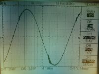
Picture below shows a zoomed-in region, of the valley of the sine:
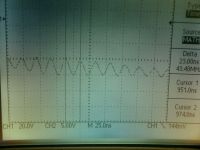
The frequency of the oscillations are about 43MHz, and have a maximum amplitude of about 20 Vpk-pk (at 160Vpk-pk fundamental signal at 136 kHz)
While I was initially driving the induction heater inverter manually, using a function generator, I noticed that when my drive frequency was below resonance, the 'dirty stuff' was just after the peaks (i.e. to the right of the hills and valleys of the sine). Driving it below resonant frequency is supposedly bad due to forced commutation of the FETs.
But now is the first time I see this dirt at a frequency above resonance (when detuning the inverter for less power, i.e. increasing the VCO control voltage, to reduce power throughput).
The questions:
- is this dirt on the tank voltage normal? Is it acceptable, at its present amplitude?
- is there anything that should be done about it?
- if so, what could be done about it (apart from tuning to exact resonance)
Or maybe I worry too much, as driving the IH at a frequency above resonance is supposed to be safe....
Peter.
Dinges, Sun Jan 31 2010, 07:25PM
One thing I've noticed when running the induction heater under automatic control is that, when it detunes to a frequency higher than resonance, I get some dirt on the tank voltage sine - see scope images.

Picture below shows a zoomed-in region, of the valley of the sine:

The frequency of the oscillations are about 43MHz, and have a maximum amplitude of about 20 Vpk-pk (at 160Vpk-pk fundamental signal at 136 kHz)
While I was initially driving the induction heater inverter manually, using a function generator, I noticed that when my drive frequency was below resonance, the 'dirty stuff' was just after the peaks (i.e. to the right of the hills and valleys of the sine). Driving it below resonant frequency is supposedly bad due to forced commutation of the FETs.
But now is the first time I see this dirt at a frequency above resonance (when detuning the inverter for less power, i.e. increasing the VCO control voltage, to reduce power throughput).
The questions:
- is this dirt on the tank voltage normal? Is it acceptable, at its present amplitude?
- is there anything that should be done about it?
- if so, what could be done about it (apart from tuning to exact resonance)
Or maybe I worry too much, as driving the IH at a frequency above resonance is supposed to be safe....
Peter.
Re: induction heater project - feedback on inverter.
IamSmooth, Sun Jan 31 2010, 08:57PM
The regular intervals of your "dirt" suggests this is during switching. Maybe your deadtime between switching is too long? I am not knowledgeable enough to tell. How do you control your switch timing?
You said it locks perfectly which is great. What is the frequency range of your PLL? What happens if you put something other than a bolt inside like a chunk of copper or a small steel nut? I found with my topology it locks onto resonance, but is usually a little off and needs to get perfectly tuned by adjusting a pot to my integrator feedback loop.
As soon I have learned enough I am going to build an 8kw unit using a microprocessor to lock onto resonance using a PLL/VCO. I am hoping to have resolution down to 50hz increments for scaning a frequency range of 50-150khz.
Re: induction heater project - feedback on inverter.
Steve Conner, Sun Jan 31 2010, 09:27PM
The dirt is just switching transients. Above resonance, the FETs don't switch at zero current any more, so they start to make these little bursts of RF as they suddenly interrupt this non-zero current. They get into the ground system and appear just about everywhere. (And make you fail your EMC test if you're not careful!)
It's not a problem. If it looked like this -that might be a problem :)
Steve Conner, Sun Jan 31 2010, 09:27PM
The dirt is just switching transients. Above resonance, the FETs don't switch at zero current any more, so they start to make these little bursts of RF as they suddenly interrupt this non-zero current. They get into the ground system and appear just about everywhere. (And make you fail your EMC test if you're not careful!)
It's not a problem. If it looked like this
 -that might be a problem :)
Re: induction heater project - feedback on inverter.
Dinges, Sun Jan 31 2010, 09:32PM
Could that explain why the dirt only occurs at off-resonance frequencies?
One other thing I noticed is that the noise in the valleys is much more noticeable than in the hills.
Will have to scope the inverter waveshape tomorrow, that may provide more clues; just realized that tank-voltage is not really relevant, but it just happened I was looking at the tank waveshape when I was using the induction heater. Will be interesting to see what's actually happening to the inverter waveshape.
Switch timing is controlled by the PLL - it takes one input signal for the phase comparator from the tank capacitor (tank voltage), and the other one from the inverter (an extra single-turn winding over the coupling transformer), thereby cancelling any phase-errors that you'd get by sampling the tank voltage (one input for the phase comparator) and connecting the other input (pin 3 of the 4046) straight to the VCO output (pin 4 of the 4046). Any timing delays in the gatedriver and inverter get translated into phase errors and off-resonance locking, I think.
I had a lot of problems earlier with the circuit - I think there was too much phase delay between the two signals, due to different delay times (extra inverters, etc.). After solving that one, it locked properly. I haven't added any manually tunable phase delays (RC-filters) to deliberately slow one of the two phase comparator signals down, to tune to slightly above resonance, instead of exactly on resonance.
Frequency range is from 115-155 kHz, with VCO voltage at 0 and 15V, respectively.
It locks and starts heating. Have tried larger pieces of steel, copper pipe (which got barely lukewarm - but the tank coil got very hot) and aluminium pipe (which got nicely warm; resonant frequency with the aluminium workpiece had actually risen by about 15 kHz, to my surprize: was resonant at about 150 kHz.)
It seems to be pretty good on frequency, as far as I can tell. No fiddling of any sort required.
One thing that surprized me is that by adjusting the power control knob (which detunes the VCO to a higher frequency) has less effect than I expected. Don't get me wrong, I can reduce output perfectly well to safe levels (~100W) by detuning, but I had expected 1-2 kHz difference to have a lot of effect; in practice, the difference is smaller than I'd expect. Maybe the Q (quality factor) of my tank circuit is lower than yours?
Then again, with a load in it, the difference in loaded Q is probably negligeable?
Sounds like an interesting project that I'd follow with much interest.
Peter.
Dinges, Sun Jan 31 2010, 09:32PM
wrote ...
Maybe your deadtime between switching is too long?
Maybe your deadtime between switching is too long?
Could that explain why the dirt only occurs at off-resonance frequencies?
One other thing I noticed is that the noise in the valleys is much more noticeable than in the hills.
Will have to scope the inverter waveshape tomorrow, that may provide more clues; just realized that tank-voltage is not really relevant, but it just happened I was looking at the tank waveshape when I was using the induction heater. Will be interesting to see what's actually happening to the inverter waveshape.
wrote ...
I am not knowledgeable enough to tell. How do you control your switch timing?
I am not knowledgeable enough to tell. How do you control your switch timing?
Switch timing is controlled by the PLL - it takes one input signal for the phase comparator from the tank capacitor (tank voltage), and the other one from the inverter (an extra single-turn winding over the coupling transformer), thereby cancelling any phase-errors that you'd get by sampling the tank voltage (one input for the phase comparator) and connecting the other input (pin 3 of the 4046) straight to the VCO output (pin 4 of the 4046). Any timing delays in the gatedriver and inverter get translated into phase errors and off-resonance locking, I think.
I had a lot of problems earlier with the circuit - I think there was too much phase delay between the two signals, due to different delay times (extra inverters, etc.). After solving that one, it locked properly. I haven't added any manually tunable phase delays (RC-filters) to deliberately slow one of the two phase comparator signals down, to tune to slightly above resonance, instead of exactly on resonance.
wrote ...
What is the frequency range of your PLL?
What is the frequency range of your PLL?
Frequency range is from 115-155 kHz, with VCO voltage at 0 and 15V, respectively.
wrote ...
What happens if you put something other than a bolt inside like a chunk of copper or a small steel nut?
What happens if you put something other than a bolt inside like a chunk of copper or a small steel nut?
It locks and starts heating. Have tried larger pieces of steel, copper pipe (which got barely lukewarm - but the tank coil got very hot) and aluminium pipe (which got nicely warm; resonant frequency with the aluminium workpiece had actually risen by about 15 kHz, to my surprize: was resonant at about 150 kHz.)
wrote ...
I found with my topology it locks onto resonance, but is usually a little off and needs to get perfectly tuned by adjusting a pot to my integrator feedback loop.
I found with my topology it locks onto resonance, but is usually a little off and needs to get perfectly tuned by adjusting a pot to my integrator feedback loop.
It seems to be pretty good on frequency, as far as I can tell. No fiddling of any sort required.
One thing that surprized me is that by adjusting the power control knob (which detunes the VCO to a higher frequency) has less effect than I expected. Don't get me wrong, I can reduce output perfectly well to safe levels (~100W) by detuning, but I had expected 1-2 kHz difference to have a lot of effect; in practice, the difference is smaller than I'd expect. Maybe the Q (quality factor) of my tank circuit is lower than yours?
Then again, with a load in it, the difference in loaded Q is probably negligeable?
wrote ...
As soon I have learned enough I am going to build an 8kw unit using a microprocessor to lock onto resonance using a PLL/VCO. I am hoping to have resolution down to 50hz increments for scaning a frequency range of 50-150khz.
As soon I have learned enough I am going to build an 8kw unit using a microprocessor to lock onto resonance using a PLL/VCO. I am hoping to have resolution down to 50hz increments for scaning a frequency range of 50-150khz.
Sounds like an interesting project that I'd follow with much interest.
Peter.
Re: induction heater project - feedback on inverter.
Dinges, Sun Jan 31 2010, 09:39PM
Ok, I see. That actually makes good sense. Am reassured now.
Yikes! And here I was worrying....
Thanks for clarifying, Steve.
Peter.
Dinges, Sun Jan 31 2010, 09:39PM
Steve McConner wrote ...
The dirt is just switching transients. Above resonance, the FETs don't switch at zero current any more, so they start to make these little bursts of RF as they suddenly interrupt this non-zero current.
The dirt is just switching transients. Above resonance, the FETs don't switch at zero current any more, so they start to make these little bursts of RF as they suddenly interrupt this non-zero current.
Ok, I see. That actually makes good sense. Am reassured now.
wrote ...
It's not a problem. If it looked like this -that might be a problem
It's not a problem. If it looked like this -that might be a problem
Yikes! And here I was worrying....
Thanks for clarifying, Steve.
Peter.
Re: induction heater project - feedback on inverter.
GeordieBoy, Sun Jan 31 2010, 09:42PM
As Steve Conner said, those tiny little bits of ringing on the tank voltage waveform are nothing to worry about.
When operating above resonance, the load current abruptly switches from the MOSFET which is turning off to the FWD across the opposite MOSFET before that device turns on.
This "commutation" results in a relatively sharp slew of the voltage from one rail (for instance the bottom supply rail) when the bottom MOSFET is on, to the top rail when the FWD catches the load current and clamps it to the supply. It is this high dv/dt that causes the ringing in VHF range.
Don't worry about it though it is perfectly normal! (If you really wanted to go for a low EMI design to meet approvals you would put lossless snubber capacitors across the MOSFETs and increase the dead-time to control the dv/dt during the commutation time!)
It's really not necessary though As long as you operate in the ZVS region above resonance you won't get the horrendous reverse-recovery ringing!
-Richie,
GeordieBoy, Sun Jan 31 2010, 09:42PM
As Steve Conner said, those tiny little bits of ringing on the tank voltage waveform are nothing to worry about.
When operating above resonance, the load current abruptly switches from the MOSFET which is turning off to the FWD across the opposite MOSFET before that device turns on.
This "commutation" results in a relatively sharp slew of the voltage from one rail (for instance the bottom supply rail) when the bottom MOSFET is on, to the top rail when the FWD catches the load current and clamps it to the supply. It is this high dv/dt that causes the ringing in VHF range.
Don't worry about it though it is perfectly normal! (If you really wanted to go for a low EMI design to meet approvals you would put lossless snubber capacitors across the MOSFETs and increase the dead-time to control the dv/dt during the commutation time!)
It's really not necessary though
 As long as you operate in the ZVS region above resonance you won't get the horrendous reverse-recovery ringing!
-Richie,
Re: induction heater project - feedback on inverter.
IamSmooth, Sun Jan 31 2010, 11:11PM
If you look at this page in the middle

you will see the transition from ModeIII to ModeIV, which Richie is talking about. It is the transition from one supply rail to the next. I believe I got this image from one of his references. Thanks Richie.
Dinges, you mentioned that you are looking at the cap-tank voltage and what other waveform? Try looking at the inverter voltage and inverter current simultaneously. This will be make it easier to see how close you are to true zero-crossing. When it is dead-on you will have the most power. I keep it just a little bit higher than resonance.
IamSmooth, Sun Jan 31 2010, 11:11PM
If you look at this page in the middle

you will see the transition from ModeIII to ModeIV, which Richie is talking about. It is the transition from one supply rail to the next. I believe I got this image from one of his references. Thanks Richie.
Dinges, you mentioned that you are looking at the cap-tank voltage and what other waveform? Try looking at the inverter voltage and inverter current simultaneously. This will be make it easier to see how close you are to true zero-crossing. When it is dead-on you will have the most power. I keep it just a little bit higher than resonance.
Re: induction heater project - feedback on inverter.
GeordieBoy, Mon Feb 01 2010, 02:03PM
> ...you will see the transition from ModeIII to ModeIV, which Richie is talking about. It is the transition from one supply rail to the next.
If you take the switch capacitances into account (or put additional caps across the switches) then the inverter actually has 6 switching phases (or modes as you call them) instead of 4.
They would be as follows:
1. Load current flows down through top IGBT channel,
2. Load current charges top cap, and discharges bottom capacitor,
(This capacitor charging action is what slews the output voltage from the top rail to the bottom rail during the deadtime,)
3. Load current flows up through bottom diode,
(Output is now clamped to negative supply rail.)
4. Load current flows down through bottom IGBT channel,
5. Load current charges bottom cap, and discharges top capacitor,
(This capacitor charging action is what slews the output voltage from the bottom rail to the top rail during the deadtime,)
6. Load current flows up through top diode,
(Output is now clamped to positive supply rail.)
It is the inductive load current freewheeling during the dead-time that actually drives the mid-point of the inverter smoothly from one supply rail to the other.
When this is working optimally you get a nice clean trapezoidal output voltage waveform from the inverter where the slopes of the rising and falling edges are quite noticeable. The relatively low slew rate massively reduces EMI generation from the inverter, whilst the ZVS and "turn-off snubbing" from the capacitors achieves very low switching losses indeed.
-Richie,
Re: induction heater project - feedback on inverter.
Dinges, Mon Feb 01 2010, 04:18PM
I notice that the 4046 VCO's voltage isn't neatly 7.5 V( middle of supply voltage) which would happen at 90 degree phase difference between the two comparator inputs, but is sometimes below it, at about 5.5V; does this mean that I'm not exactly driving it at resonance? Or are there phase delays somewhere in the signal path? And does this mean that my phase is off by ((7.5V-5.5V)/15V)* 180 deg = 24 degrees?
Either way, it seems to work very nicely. When retuning for *exact* resonance, power throughput hardly increases. Is this because of the low Q of a loaded workcoil? (as opposed to an unloaded coil, which likely has Q's approaching 200)
On another subject: I'm now boxing it all up in a case, but, in the mean time, am pondering a follow-up induction heater project that should go up to about 2.5-3 kW. Already have an old 48V/100A (7.2kVA input) ex-telecom battery charger in 19" rack, which has 8 big MOSFETs (MTE30N50E; 30A, 500V, Rds,on=0.15 ohm, ISOTOP http://www.datasheetcatalog.org/datasheet/motorola/MTE30N50E.pdf) in full-bridge configuration (2 FETs parallel per leg); see pictures below.
(in the picture above the pencil points to the two cooling fins that contain the 8 FETs; below the pencil is one of the two ferrite transformers (with aluminium cooling fins...); to the right of the pencil is the cooling fin with the rectifiers, also ISOTOP); on the rear of the rack are 3 large fans that blow air over the fins, which have been removed for this picture)
I intend to re-use the cabinet and the power-section (with some modifications); saves a lot of the mechanical work. Just add a PLL controller and tank circuit and we're finished.
The questions:
- does a full-bridge configuration offer any advantages over a half-bridge in this configuration?
- how to determine the maximum frequency these FETs can be driven? What determines the upper-frequency limit? Somehow I doubt I can drive these FETs at the same frequency (140kHz) as my present induction heater, or could I?
Peter.
Dinges, Mon Feb 01 2010, 04:18PM
I notice that the 4046 VCO's voltage isn't neatly 7.5 V( middle of supply voltage) which would happen at 90 degree phase difference between the two comparator inputs, but is sometimes below it, at about 5.5V; does this mean that I'm not exactly driving it at resonance? Or are there phase delays somewhere in the signal path? And does this mean that my phase is off by ((7.5V-5.5V)/15V)* 180 deg = 24 degrees?
Either way, it seems to work very nicely. When retuning for *exact* resonance, power throughput hardly increases. Is this because of the low Q of a loaded workcoil? (as opposed to an unloaded coil, which likely has Q's approaching 200)
On another subject: I'm now boxing it all up in a case, but, in the mean time, am pondering a follow-up induction heater project that should go up to about 2.5-3 kW. Already have an old 48V/100A (7.2kVA input) ex-telecom battery charger in 19" rack, which has 8 big MOSFETs (MTE30N50E; 30A, 500V, Rds,on=0.15 ohm, ISOTOP http://www.datasheetcatalog.org/datasheet/motorola/MTE30N50E.pdf) in full-bridge configuration (2 FETs parallel per leg); see pictures below.


(in the picture above the pencil points to the two cooling fins that contain the 8 FETs; below the pencil is one of the two ferrite transformers (with aluminium cooling fins...); to the right of the pencil is the cooling fin with the rectifiers, also ISOTOP); on the rear of the rack are 3 large fans that blow air over the fins, which have been removed for this picture)


I intend to re-use the cabinet and the power-section (with some modifications); saves a lot of the mechanical work. Just add a PLL controller and tank circuit and we're finished.
The questions:
- does a full-bridge configuration offer any advantages over a half-bridge in this configuration?
- how to determine the maximum frequency these FETs can be driven? What determines the upper-frequency limit? Somehow I doubt I can drive these FETs at the same frequency (140kHz) as my present induction heater, or could I?
Peter.
Re: induction heater project - feedback on inverter.
IamSmooth, Mon Feb 01 2010, 04:21PM
Richie, is there an optimal capacitance value or will any reasonable value work? I have 1.0uf snubbers. Would 1.5uf be better? If there is an optimal value, how would one calculate it?
ALso, during deadtime both mosfets are off, so how is the capacitor discharging?
The VCO takes the voltage required to achieve resonant frequency. If your supply is 15v and Fres is exactly at the midpoint of your PLL frequency range set by your R1 and R2 resistors, then 7.5v yields the right value. If your frequency is not the midpoint of your range you will need a different voltage value to get the right frequency. As the resonant point changes VCO will also change during the heating.
IamSmooth, Mon Feb 01 2010, 04:21PM
Richie, is there an optimal capacitance value or will any reasonable value work? I have 1.0uf snubbers. Would 1.5uf be better? If there is an optimal value, how would one calculate it?
ALso, during deadtime both mosfets are off, so how is the capacitor discharging?
Dinges wrote ...
I notice that the 4046 VCO's voltage isn't neatly 7.5 V( middle of supply voltage) which would happen at 90 degree phase difference between the two comparator inputs, but is sometimes below it, at about 5.5V; does this mean that I'm not exactly driving it at resonance? Or are there phase delays somewhere in the signal path? And does this mean that my phase is off by ((7.5V-5.5V)/15V)* 180 deg = 24 degrees?
I notice that the 4046 VCO's voltage isn't neatly 7.5 V( middle of supply voltage) which would happen at 90 degree phase difference between the two comparator inputs, but is sometimes below it, at about 5.5V; does this mean that I'm not exactly driving it at resonance? Or are there phase delays somewhere in the signal path? And does this mean that my phase is off by ((7.5V-5.5V)/15V)* 180 deg = 24 degrees?
The VCO takes the voltage required to achieve resonant frequency. If your supply is 15v and Fres is exactly at the midpoint of your PLL frequency range set by your R1 and R2 resistors, then 7.5v yields the right value. If your frequency is not the midpoint of your range you will need a different voltage value to get the right frequency. As the resonant point changes VCO will also change during the heating.
Re: induction heater project - feedback on inverter.
GeordieBoy, Mon Feb 01 2010, 10:02PM
> Richie, is there an optimal capacitance value or will any reasonable value work?
I really wouldn't worry about the dv/dt during the deadtime unless you are wanting to reduce EMI as much as possible. Companies that design commercial Induction Heaters for sale have to worry about this stuff.
> I have 1.0uf snubbers. Would 1.5uf be better?
Way way to big. Usually something between 220pF and 1nF is best to control the voltage slew-rate. It depends on the operating frequency, the amount of dead-time and the power level though. Lower operating frequency, more dead-time and high-power all make the optimal snubbing capacitance larger.
> ALso, during deadtime both mosfets are off, so how is the capacitor discharging?
Even though both MOSFETs are off during the dead-time, current continues to flow through the inductive part of the load. (Inductors act to prevent current from changing instantaneously.) It is this free-wheeling current that charges one device's capacitance and discharges the other in order to slew the inverter mid-point voltage from one rail to the other.
-Richie,
Re: induction heater project - feedback on inverter.
IamSmooth, Mon Feb 01 2010, 11:37PM
I see it now. I was looking at the wrong capacitor.
I am about to remake my HV DC power for an 8kw unit. My rectifier is 1000v/80A. That should be enough. I was going to have 50-100uf of capacitor for a voltage doubler. Is that reasonable to keep the PF close to unity? I currently have 1500uf.
Re: induction heater project - feedback on inverter.
Dinges, Tue Feb 02 2010, 11:42AM
Richie, I think you are correct. Decided to scope both the gatedrive waveshape and the tankvoltage, and that was very telling:
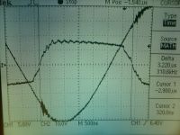
Sine is the tank voltage, squarish-wave is the gate drive signal.
Notice that my gatedrive isn't entirely symmetric, due to an extra inverter (NAND gate) in a part of the gatedriver (see schematic here: http://picasaweb.google.com/motorconversion/Induction_heater#5433602260934568338); this extra NAND gate introduces 75ns delay (as measured), and accounts for the difference in rise and fall times of the gatedrive waveshape, of about 100ns (hard to estimate).
As can be seen in the top picture, the downslope of the gatedriver is a tad slower (by about 100ns) than the upslope; and notice that the noise on the tank voltage is larger in the case where the FETs switch faster.
So indeed, it looks like more deadtime leads to less RFI... but also to more switching losses in the FETs, as more time is spent dwelling in the linear region. I guess this is where the 'lossless' snubbers come in.
Oh, btw, I do have snubbers in the inverter, consisting of 2n2 capacitors in series with a 10R resistor; 3 snubbers in total, two over the switching transistors, and another one over the primary of the coupling transformer.
Peter.
Dinges, Tue Feb 02 2010, 11:42AM
Richie wrote ...
I really wouldn't worry about the dv/dt during the deadtime unless you are wanting to reduce EMI as much as possible. Companies that design commercial Induction Heaters for sale have to worry about this stuff.
I really wouldn't worry about the dv/dt during the deadtime unless you are wanting to reduce EMI as much as possible. Companies that design commercial Induction Heaters for sale have to worry about this stuff.
Richie, I think you are correct. Decided to scope both the gatedrive waveshape and the tankvoltage, and that was very telling:

Sine is the tank voltage, squarish-wave is the gate drive signal.
Notice that my gatedrive isn't entirely symmetric, due to an extra inverter (NAND gate) in a part of the gatedriver (see schematic here: http://picasaweb.google.com/motorconversion/Induction_heater#5433602260934568338); this extra NAND gate introduces 75ns delay (as measured), and accounts for the difference in rise and fall times of the gatedrive waveshape, of about 100ns (hard to estimate).
As can be seen in the top picture, the downslope of the gatedriver is a tad slower (by about 100ns) than the upslope; and notice that the noise on the tank voltage is larger in the case where the FETs switch faster.
So indeed, it looks like more deadtime leads to less RFI... but also to more switching losses in the FETs, as more time is spent dwelling in the linear region. I guess this is where the 'lossless' snubbers come in.
Oh, btw, I do have snubbers in the inverter, consisting of 2n2 capacitors in series with a 10R resistor; 3 snubbers in total, two over the switching transistors, and another one over the primary of the coupling transformer.
Peter.
Re: induction heater project - feedback on inverter.
Hernan, Tue Feb 02 2010, 11:53AM
Hi all,
Dinges, I had noticed the same waveform in my LCLR IH too when is slightly above resonance.
my mosfets haven`t explode yet.
I dont know why but I also noticed that this switching transient gets more pronounced when the tank is away from the inverter and matching inductor.
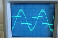

Re: induction heater project - feedback on inverter.
Dinges, Tue Feb 02 2010, 12:54PM
Hello Hernán,
Good to hear from you. As you can see, I've used your design as the basis for my own, but with some modifications, and weeding out some errors. Nevertheless, was the best design I found on the net - thanks for publishing your works.
In your scope image, it looks as if you're driving the tank circuit below resonance, not above it, from what I can tell, as your 'dirt' is just after the peaks and valleys of the sine, not before. And yes, the hash gets more pronounced the lower your drive frequency becomes, once you are driving the tank below resonance. If you try driving your inverter & tank with a function generator (as opposed to the VCO-out from the 4046), you can play with it yourself and directly see the effect of drive frequency.
Oh, just thought of a way to make the gatedrive perfectly symmetrical: just introduce slightly more delay in the signal path that has less one inverter: slightly increase the resistor from 1k8 to 2k0, or increase the delay capacitor from 100p to 120p (the RC network that in your original schematic is 10k and 1n, in the gatedriver). Changing the timing of one of the signal paths should make the gatedriver waveshape perfectly symmetrical - but doesn't seem worth the bother.
Hernán, have you tried the series topology for driving your induction heater? Your design seems to work fine with it, in my experience.
Peter.
Re: induction heater project - feedback on inverter.
Hernan, Wed Feb 03 2010, 12:04AM
Peter, I`m glad that my schematic was useful to you.
yes, you are right the picture shows that the sinusoidal tank voltage is a bit below resonance.I haven`t got a picture with the tank tuned above resonance but it's similar with your picture. I`ll post it later
yes,it is very good idea to add some delay on the signal path that has one less nand gate to obtain symetrical gate waveform..I need only to change some component values
I meant the workcoil and tank capacitor located some distance away from the inverter & matching inductor. the tank voltage waveform looks worse in this situation.
recently I built a series resonant IH ,with 1.5kw and frq. about 180Khz with PLL control circuit to melt bronze, aluminum and copper . I used other schematic( less components). I'll post it later too
thank for your corrections
Hernán
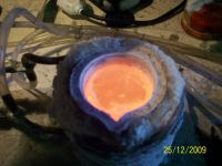

Print this page