High Frequency Solid State Tesla Coil
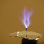
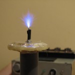
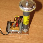
radhoo, Sun Dec 06 2009, 10:48PMMy first SSTC is a high frequency solid state tesla coil. Complete construction details here:
my blog
In only uses one mosfet (IRFP 460) and runs on 50V to 100V input voltage.
Some pictures:


Re: High Frequency Solid State Tesla Coil
Finn Hammer, Sun Dec 06 2009, 11:28PM
That´s one nice little coil.
I like the simplicity, and VTTC like construction.
Cheers, Finn Hammer
Finn Hammer, Sun Dec 06 2009, 11:28PM
That´s one nice little coil.
I like the simplicity, and VTTC like construction.
Cheers, Finn Hammer
Re: High Frequency Solid State Tesla Coil
doctor electrons, Mon Dec 07 2009, 01:26AM
Nice work! Very nice indeed!
doctor electrons, Mon Dec 07 2009, 01:26AM
Nice work! Very nice indeed!
Re: High Frequency Solid State Tesla Coil
MRacerxdl, Mon Dec 07 2009, 01:27AM
Very good work! I like the "no wires looking" secondary =D
MRacerxdl, Mon Dec 07 2009, 01:27AM
Very good work! I like the "no wires looking" secondary =D
Re: High Frequency Solid State Tesla Coil
Mads Barnkob, Mon Dec 07 2009, 04:59AM
Looking good, reminds me of the simple 2n3055 flyback driver, what is your resonant frequency?
Mads Barnkob, Mon Dec 07 2009, 04:59AM
Looking good, reminds me of the simple 2n3055 flyback driver, what is your resonant frequency?
Re: High Frequency Solid State Tesla Coil
raff, Mon Dec 07 2009, 05:59AM
radhoo,
nice coil ...small and compact.. why not try IRFP250 or 260? more current rating BUT only 200V device. though
raff, Mon Dec 07 2009, 05:59AM
radhoo,
nice coil ...small and compact.. why not try IRFP250 or 260? more current rating BUT only 200V device. though
Re: High Frequency Solid State Tesla Coil
radhoo, Mon Dec 07 2009, 12:28PM
Thank you all for the appreciation.
@raff, the IRFP460 produced better results then the IRFP260, but it is true that the coil was already tuned for the IRFP460 when I tested the 260 (without re-tweaking it for the new mosfet). However with the IRFP 260 I had no sparks, not even when touching the breakpoint with the screwdriver.
@Mads, I suspect it is ~4.6MHz, but I currently do not have the tools to measure it correctly.
Re: High Frequency Solid State Tesla Coil
Mates, Mon Dec 07 2009, 04:18PM
Hi,
Cool - I like the simplicity.
I have few comments. How you can be sure your FET is turned on fully? I mean, this concept is originally developed for bipolar transitors. And same question from the other side - How you can be sure, that your gate is not exposed to overvoltage. I suggest as solution to use some transils or zeners to clamp the voltage at 15V. Than you could add few more turns until the diodes get hot (but not too much). Than you can be sure your FET gets what she needs. It’s just a suggestion but might be improvement for your concept.
Cheers Mates
Re: High Frequency Solid State Tesla Coil
Dr. Dark Current, Mon Dec 07 2009, 06:32PM
I have been thinking about this concept too, your design could probably be improved by putting a diode in series with the drain (to not distort the sine wave) and using a gate self-biasing circuit (so the FET conducts only a fraction of the cycle like in a VTTC).
Of course the gate voltage should be always clamped by two 20V "back to back" zeners.
Re: High Frequency Solid State Tesla Coil
radhoo, Mon Dec 07 2009, 10:26PM
Mates, Dr. Kilovolt, thanks for the good suggestions.
Indeed, most probably, the gate is driven in overvolted mode and this might just be what it needs to fully open the mosfet but... will kill it eventually.
I was thinking of adding a zenner myself, so I'll check this and report back.
I would like to know more on the purpose of "Than you could add few more turns until the diodes get hot (but not too much). "
To obtain resonance, I've moved the primary+feedback coils closer or further over the secondary coil (embedded inside the visible tube).. Regarding the Mosfet.... SHE? never knew that
Dr.Kilovolt, I would need more details for the self-biasing gate circuit .
To power this coil, I'm using a 24V/10A max power source. The alternating current goes through a voltage tripler (3x3300uF caps), so I get aprox. 100V when no load is connected. The problem is that there are some high voltage spikes going back to my power source. What protection should work best?
vasil also suggested connecting small caps between he wires comming from the coil and the ground.
currently the driver circuit is not shielded, should this be of any concern? The RF field is quite strong in the close proximity of the operating coil.
radhoo, Mon Dec 07 2009, 10:26PM
Mates, Dr. Kilovolt, thanks for the good suggestions.
Indeed, most probably, the gate is driven in overvolted mode and this might just be what it needs to fully open the mosfet but... will kill it eventually.
I was thinking of adding a zenner myself, so I'll check this and report back.
I would like to know more on the purpose of "Than you could add few more turns until the diodes get hot (but not too much). "
To obtain resonance, I've moved the primary+feedback coils closer or further over the secondary coil (embedded inside the visible tube).. Regarding the Mosfet.... SHE?
 never knew that
Dr.Kilovolt, I would need more details for the self-biasing gate circuit .
To power this coil, I'm using a 24V/10A max power source. The alternating current goes through a voltage tripler (3x3300uF caps), so I get aprox. 100V when no load is connected. The problem is that there are some high voltage spikes going back to my power source. What protection should work best?
vasil also suggested connecting small caps between he wires comming from the coil and the ground.
currently the driver circuit is not shielded, should this be of any concern? The RF field is quite strong in the close proximity of the operating coil.
Re: High Frequency Solid State Tesla Coil
teravolt, Tue Dec 08 2009, 04:18AM
does the performance change if you change the .68uf or .22uf caps
teravolt, Tue Dec 08 2009, 04:18AM
does the performance change if you change the .68uf or .22uf caps
Re: High Frequency Solid State Tesla Coil
Dr. Dark Current, Tue Dec 08 2009, 01:03PM
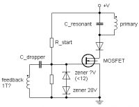
Here is my concept schematic. The problem I came to was that the circuit would need less than 1 turn on the feedback, so my idea is to use a "dropper" capacitor which forms a capacitive divider with the gate (so something in the nf range to set the peak-to-peak gate voltage to some 20 volts or even less). Becuase the gate capacitance is not constant, it might need a parallel capacitor.
The upper zener diode limits the positive peak gate voltage, it might be something like few to several volts, and together with gate voltage amplitude and gate threshold voltage sets the conduction angle.
But this is just a concept and I have no idea if this will work, so try at your own risk

Dr. Dark Current, Tue Dec 08 2009, 01:03PM
radhoo wrote ...
Dr.Kilovolt, I would need more details for the self-biasing gate circuit .
Dr.Kilovolt, I would need more details for the self-biasing gate circuit .
Here is my concept schematic. The problem I came to was that the circuit would need less than 1 turn on the feedback, so my idea is to use a "dropper" capacitor which forms a capacitive divider with the gate (so something in the nf range to set the peak-to-peak gate voltage to some 20 volts or even less). Becuase the gate capacitance is not constant, it might need a parallel capacitor.
The upper zener diode limits the positive peak gate voltage, it might be something like few to several volts, and together with gate voltage amplitude and gate threshold voltage sets the conduction angle.
But this is just a concept and I have no idea if this will work, so try at your own risk


Re: High Frequency Solid State Tesla Coil
Mates, Tue Dec 08 2009, 10:50PM
Hi Jan,
what is the reason for the diode in your scheme?
Mates, Tue Dec 08 2009, 10:50PM
Hi Jan,
what is the reason for the diode in your scheme?
Re: High Frequency Solid State Tesla Coil
teravolt, Wed Dec 09 2009, 04:20AM
It looks to me that the diode prevents reversal on the fet. If a inductor was placed in series with R-start it would present a higher impedance to your feadback side of the circuit. if you could take the V+ to five or six hundred volts I think it would work well. it is basicaly the same armstong oscillator as a VTTC.
Re: High Frequency Solid State Tesla Coil
fatboyslim, Wed Dec 09 2009, 05:19AM
Absolutely Fantastic work there. I love its simplicity and am seriously considering building one. I just have one question. How were you able to obtain the 50-100v DC required to operate the circuit? Also what is the minimum amperage required? Please help!
fatboyslim, Wed Dec 09 2009, 05:19AM
Absolutely Fantastic work there. I love its simplicity and am seriously considering building one. I just have one question. How were you able to obtain the 50-100v DC required to operate the circuit? Also what is the minimum amperage required? Please help!
Re: High Frequency Solid State Tesla Coil
Dr. Dark Current, Wed Dec 09 2009, 08:39AM
Dr. Dark Current, Wed Dec 09 2009, 08:39AM
Mates wrote ...
Hi Jan,
what is the reason for the diode in your scheme?
Mates, the MOSFET drives a parallel resonant load at its resonant frequency so it switches a sine wave. It is quite likely that after it starts conducting each cycle, the sine wave "undershoots" the ground and goes negative for a while. If there was no diode, it would be clamped by the MOSFET diode, the energy recycled to the filter capacitor, the sinewave would get distorted and efficiency would go down.Hi Jan,
what is the reason for the diode in your scheme?
Re: High Frequency Solid State Tesla Coil
Joyeep, Thu Jan 21 2010, 02:59PM
å‘出好ï¼è€å…„,干的ä¸é”™ï¼Œç»§ç»åšçš„æ› ´å¥½ï¼
Joyeep, Thu Jan 21 2010, 02:59PM
å‘出好ï¼è€å…„,干的ä¸é”™ï¼Œç»§ç»åšçš„æ› ´å¥½ï¼
Re: High Frequency Solid State Tesla Coil
Andri, Thu Jan 21 2010, 05:58PM
Right...
Andri, Thu Jan 21 2010, 05:58PM
ZhuNian wrote ...
å‘出好ï¼è€å…„,干的ä¸é”™ï¼Œç»§ç»åšçš„æ ›´å¥½ï¼
å‘出好ï¼è€å…„,干的ä¸é”™ï¼Œç»§ç»åšçš„æ ›´å¥½ï¼
Right...
Re: High Frequency Solid State Tesla Coil
radhoo, Sun Feb 14 2010, 09:08PM
While this concept seemed like an easy victory, for some reason my first tests where unable to produce a self sustainable oscillation. In my setup everything was built in an empirical way and probably so were the results. But I hope to get another try and re-think the setup in more detail.
Meanwhile, I plan to use the secondary I've built with a different approach: a single mosfet or a half bridge, triggered by a little Atmel ATTINY45 with a pot to adjust frequency 0..20MHz.
Comments?
Print this page