
Miniature wireless power demonstrator
Marko, Mon Aug 10 2009, 11:03PM20. 04. 2010 - update:
I added little FAQ summarizing the questions I've been most frequently asked about the project. I may update it with time and feel free to post a question you think might be suitable for me to add.
**FAQ**
- Are there kits or complete models available for sale?
Not yet as I'm currently unable to build any. I might make some this summer if I find increased interest, although I'm not promising anything as I have a number of hurdles to overcome regarding sales.
- I can't find the WIMA FKP capacitors like you used. Can I use ceramic/MKP/other type of capacitors available in my store?
No. Other types of capacitors, if they work at all are most likely going to be very lossy and overheat and melt in minutes.
Capacitors don't really even need to be WIMA brand, pretty much any polypropylene capacitors should work well.
This includes CDE942 caps generally used by tesla coilers here, as well as various brands of 'MKP' and similar caps. MKP is somewhat more lossy than FKP but worked fine in my first designs.
- I want to use the circuit to charge a mobile phone. Can I have schematics/plans?
I just don't have time to write about it now, and if you built the circuit I think it's straightforward enough for you to figure it out yourself.
Hint: a rectifier of suitable high speed diodes and a DC/DC converter chip.
- What is the diameter of transmitting and receiving loops?
Not sure why does everyone need to know this exactly, since I don't really remember the diameter I used myself. A larger loop is going to help transmit the power somewhat farther at cost of devices being about proportionally larger. Larger loop with same capacitor will result in lower resonant frequency.
- I can't find the copper tube and wire you used for the loops, what can I do?
Choice of the conductor used is really not critical as long as there is enough surface area to keep conductivity high and avoid overheating. A 6mm copper tube is OK for the transmitter and it should be easy to find in air conditioner stores. Receiver doesn't need to use wire, copper tube is fine too. If you have a large amount of thinner wire you could make a litz conductor by twisting several of them in parallel. 15-20mm width of copper strip should also make excellent conductor for the purpose.
Having equal loops on both transmitter and receiver will make the tuning easier.
- The transmitter circuit does not oscillate, instead it shorts the power supply and one mosfet and inductor heat up rapidly, what to do?
Firstly, if you are using a version without the relay, this is a common problem, and is caused by power supply voltage rising too slowly on powerup. To fix make sure you use a switch on low voltage side, that is immediately between your power supply and the circuit, to turn the circuit ON.
If it'+s still happening, make sure:
1. that the mosfet that suffered the condition is still working
2. check for connections of your circuit, misplaced components, directions of the diodes...
3. The circuit won't run without the loop attached!
Hope this helps.
- The transmitter oscillates but I get very little power on the secondary side. What can I do to improve?
There are two problems (or two parts of a same problem, more precisely); tuning and load impedance match.
Firstly, we want both LC circuits to resonate at about the same stand-alone f0 - the best starting point is to make them both with identical loops and capacitances.
But, to achieve maximum power throughput, we will need to fine-tune the system, prefferably during runtime. This can be done by increasing or decreasing the stand-alone resonant frequency of either the receiver or the transmitter. Some of ways to acheive that are -
1. Changing the diameter of loops - may be difficult to impossible depending on the construction, probably easier on receiver. Should not be done on the transmitter while it's operating, and it's loop should be soldered down anyway.
2. Changing the tank capacitance.
3. Much more convenient to do while system is running - is to insert a large ferrite core (AM radio ferrite rod, or a TV flyback transformer core) into a loop which we want to decrease f0.
4. Alternatively, we can bring a copper or aluminium plate behind the targeted loop to do the opposite.
Secondly we want to match the load impedance to the best possible way to the ''transmission line'' we created with coupled LC circuits. Playing with the circuit you will notice that the ''tuning'' methods described above also work to match the system to different loads! There are some reasonable limits we need to follow with the load if we want best power throughput. We can't use unreasonably low (like a car headlight) nor unreasonably high load resistances (25W 230V incadescent bulb?).
I found a 24V 5W bulb to be a decent load, although I suspected 3x 12V/2W bulbs in series might have performed better.
- I want to supersize the circuit/increase the input voltage/transmit the power over a few meters?
None of those are really practical with this design. The best shot for increasing the power throughput would be to use a ferrite transformer between the active section and LC tank - I tried it and it works but at cost of even greater mosfet heatage... if you are already at this point then you probably already understand that this circuit sucks and have better ideas than it anyway.
Just increasing the voltage to the circuit as it is beyond 18V is most likely to cause it to blow up. And using higher voltage mosfets is actually just going to make the problem worse.
Transmitting power this way on a scale of meters with sub-metre sized devices at any reasonable efficiency is pretty much science fiction as of today.
- Have you been developing any new ideas on wireless power? When may we see updates?
Yes, but I'm keeping it top secret as of now. It's not going to be simple and I don't have time to explain it anyway. ANd builds are unlikely to start before this summer.
- I built the circuit, but I measured a different frequency at the transmitter than your 1.5Mhz. What is wrong with my circuit?
Nothing may be wrong, you might just have used a larger loop diameter or more capacitance than me. If parts are really closely matching mine, thenthere might be a problem. Some things to try:
1.Just try powering something if you have the receiver - if not build one from a piece of wire and a light bulb, capacitor isn't even required for proof of concept.
If you get any incadescence on the bulb then your circuit is working already! Just proceed to tune up the receiver then.
2. Look for the current drawn from the power supply. If it's less than 0.5A or more than 1A without load then something is wrong. It's recommended to use a current limited supply for initial tests.
3. Try measuring the LC tank voltage with an oscilloscope, not a frequency counter - this also has to show the peak voltage which has to be about pi*supply voltage (37V for 12V supply). Some precautions are required while doing this - the power supply must not have grounded " - " (like a PC power supply does) because placing an oscilloscope ground clip to one of 'hot' ends of LC tank will cause short circuit. In that case we need to measure with scope input set to DC input and measure between ground and one ''hot end''. This will yield a ''halfwave rectified'' waveform but the peak voltage value should remain the same.
....that's about it for now.
Update 16. 9. 2009.
Eagle files of the new PCB
]wirelesspower.zip[/file]
New update 24. 8. 2009. :
I designed a new PCB with goal of ease of replication by newbies. Including schematic with explanations. Preliminary board, may be subject to change.
]through_hole_wireless.pdf[/file]
]through_hole_wireless-schematic.pdf[/file]
]through_hole_wireless-components.pdf[/file]
I also modified the old, prototype PCB (without the relay) a bit to make it more practical to use. All components are intended to be surface mounted on the copper side so there is no drilling involved.
]pcb_old.pdf[/file]
]pcb_old_parts.pdf[/file]
******
A number of people has expressed interest into this project, and I decided it would be best to post it up here as a project thread.
The idea behind the project was to create a small tabletop demonstrator of magnetically coupled wireless power transfer, resembling a miniature version of the MIT 'witricity' device. The goal was to keep the circuit simple with easily obtainable parts, and to keep voltage and power levels low so the device is safe for handling and doesn't require special methods of cooling.
The basic idea is to feed a parallel LC tank circuit from an AC voltage source at it's resonant frequency, which allows large reactive current to circulate in the circuit while only real power is being drawn from the source. This sets up a large alternating magnetic field in the inductor, which is designed as a single conductive loop in this case.
Now, another LC tank with load attached is brought in proximity to the excited LC circuit, significant amounts of power can be transferred via weak magnetic coupling between them. This is because AC current itself in the transmitting loop is very large, and inductive reactance of the receiver loop is canceled out by the capacitor.
For a practical device, the AC voltage source had to be substituted with an appropriate oscillator, which would take feedback from the tank circuit itself and hence always drive it at it's resonant frequency.
The circuit of choice was a slightly modified royer oscillator, such as popularly used in CCFL inverters and for flyback drivers.
Input voltage was limited to 15V for safety and because the circuit tends to become unstable at higher voltages.
The idea of the prototype circuit is rather simple.


Mosfets I used were IRFZ44, but any similar ones will do. A small piece of Aluminum for a heatsink is recommended, although in prototype I just soldered the mosfets onto the PCB.
Rg were at first 50, but later increased to 100 ohms which is enough and wastes less power. Resistors need to be rated 1 watt at least and they get quite hot.
Radio frequency chokes were 100uH, at first iron powder cores, but later switched to ferrite which produced much better results.
Powdered iron cores tended to heat up from magnetic flux they picked up from the transmitting loopas well.
Diodes - 1N4148's. Similar small high-speed diodes are ok.
The LC tank circuit is the part where heavy current circulates, and is required to be sturdy. The copper pipe used as conductor heats up significantly under ~20A it's passing continuously. To handle the current while keeping losses tolerable, capacitor consists of 6 paralleled 6.8nF 1000V wima FKP1 capacitors. It's important that capacitors are polypropylene dielectric and foil or foil+film based - other types will heat up and melt in this application.
The transmitter still oscillated at relatively high frequency and had to be tuned by insertion of a ferrite core into the loop, as shown on the picture. This lowered the frequency to about 1.5Mhz without load.
Alternatively a copper or aluminum plate can be brought near the loop to increase frequency, by decreasing inductance.
Number of capacitors was later increased to 8, removing the need of additional tuning.
On the receiver side only a single capacitor and a loop of 3mm solid copper wire was used. The wire heats up significantly, though.
You can notice I used a small matching inductor in series with the load, which is a 24V 5W. It's choice was guessed at 6uH and it improved performance somewhat at larger distances.
This prototype, though, had one problem - if the supply voltage rose too slowly, such as while DC filter capacitance is charging, it tended to fail to oscillate and just keep shorting the power supply with one mosfet ON. In the final design this was solved with a relay, which acts as undervoltage lockout of sorts, applying Ugg power rapidly after supply voltage rose high enough.
Jumpers in the schematic are to allow connection of a step up autotransformer between the mosfet amplifiers and the LC tank circuit.
I provided the schematic of the finished circuit, but not the PCB since it's a fairly odd design with odd components (SMT inductors) which I thought might not be too useful for most people. PM me if the PCB layout is desired.
PCB layout and part layout for the final circuit shown in the bottom picture, along with schematic:
]parts_top.pdf[/file]
]pcb_bottom.pdf[/file]


Cheers,
Marko
Re: Miniature wireless power demonstrator
MRacerxdl, Mon Aug 10 2009, 11:24PM
Very impressive! Sometime ago I thought to made something like that as my Electronic Technician Conclusion Work, but I opted to made a Plasma Speaker instead.
But I will try someday to made one of that!
Very good work!
MRacerxdl, Mon Aug 10 2009, 11:24PM
Very impressive! Sometime ago I thought to made something like that as my Electronic Technician Conclusion Work, but I opted to made a Plasma Speaker instead.
But I will try someday to made one of that!
Very good work!
Re: Miniature wireless power demonstrator
Marko, Mon Aug 24 2009, 03:57PM
Updated with a new PCB...
Marko, Mon Aug 24 2009, 03:57PM
Updated with a new PCB...
Re: Miniature wireless power demonstrator
strider, Mon Sept 07 2009, 12:22PM
Really nice work, but I have a question about the copper tube you used in the transmitter; what is the diameter of it? Is it 3AWG (6.35mm)...? I am working on a wireless electricity project also and had successfully transferred a 27 AC 10MHz signal with an efficiency of about 68% over 3 ft. and I'll be more than happy if you can offer me some of your time to talk about this project... Also if you want I can post pictures of my work
Re: Miniature wireless power demonstrator
Mates, Mon Sept 07 2009, 01:58PM
Nice "litle" project Marko!
Honestly, I liked your SSTC based wireless project more and I'm still expecting some progress, but this is also very impressive.
We all want...
Mates, Mon Sept 07 2009, 01:58PM
Nice "litle" project Marko!
Honestly, I liked your SSTC based wireless project more and I'm still expecting some progress, but this is also very impressive.
strider wrote ...
Also if you want I can post pictures of my work
Also if you want I can post pictures of my work
We all want...
Re: Miniature wireless power demonstrator
strider, Mon Sept 07 2009, 02:31PM
Here some pictures of my work (they are not that new), I post more new 1s soon... my current work is to charge a moble phone (700m A, 3.3V) and then I'll try to go for a notebook (20V 2A)
Thanks everyone and hope to have some nice chat with you guys (my msn:**link**, skype:striderrules)


Re: Miniature wireless power demonstrator
GeordieBoy, Mon Sept 07 2009, 05:12PM
So you are using Helical antennas to direct the energy from a transmitter loop to the receiver loop?
It's a nice proof of principal but it looks a little bulky for the average laptop or mobile...

These people have pretty much nailed it technology-wise and showed me some real neat demo's of various devices like PC cooling fans, lamps, mobile phones, I-pods etc being powered by placing them anywhere on the charging pad in any orientation. The funny thing is that market uptake of this technology is very slow, that is seems nobody is really THAT interested in wireless charging afterall!
In fact the only wireless chargers that seem to be in common household appliances are those electric toothbrush and shaver chargers that enable the bathroom appliance (and it's charger) to be totally sealed to meet IP ratings for water ingress. I guess in that case the added expense of the hi-tech wireless power is justified because it solves a problem, but otherwise most consumer electronics is far too cost sensitive to include wireless power.
-Richie,
GeordieBoy, Mon Sept 07 2009, 05:12PM
So you are using Helical antennas to direct the energy from a transmitter loop to the receiver loop?
It's a nice proof of principal but it looks a little bulky for the average laptop or mobile...
These people have pretty much nailed it technology-wise and showed me some real neat demo's of various devices like PC cooling fans, lamps, mobile phones, I-pods etc being powered by placing them anywhere on the charging pad in any orientation. The funny thing is that market uptake of this technology is very slow, that is seems nobody is really THAT interested in wireless charging afterall!
In fact the only wireless chargers that seem to be in common household appliances are those electric toothbrush and shaver chargers that enable the bathroom appliance (and it's charger) to be totally sealed to meet IP ratings for water ingress. I guess in that case the added expense of the hi-tech wireless power is justified because it solves a problem, but otherwise most consumer electronics is far too cost sensitive to include wireless power.
-Richie,
Re: Miniature wireless power demonstrator
strider, Mon Sept 07 2009, 08:45PM
The pics I included above were upon 1 of my validation stages of the concept, this is why I stuck with bulky coil at the receiver side although I am tring now to go with high power, I am also trying to go smaller with the receiver side but I can't go with that easy cause I need more help and time that's why I am trying to gather all the info I can and talk with guys like you here to get more info...
Re: Miniature wireless power demonstrator
GeordieBoy, Mon Sept 07 2009, 09:12PM
The technology section of this site has some information:
At the high power end of the scale you will find that the technology exists to fill a room full of enough wireless power to run laptops, light lamps and charge phones etc. The problem is that the required field strength is many many times greater than recommended human exposure levels in safety standards. It also causes serious interference problems to equipment that doesn't contain the necessary screening to make it wireless power tolerant! Not to mention induction heating of pretty much anything conductive in the field!
-Richie
Re: Miniature wireless power demonstrator
strider, Mon Sept 07 2009, 09:28PM
Up to my testing I had reached good levels of safety according to IEEE standards however my main problem resides with efficiency as the distance increases (low tail strength) and resonance disturbance (specially at the oscillator)... Also the transmitter i am working on consists of a vacuum tube oscillator however I am trying to find high voltage high freq. oscillator using mosfets. So my work needs alot more time and readings and I cant reach high levels so fast
Re: Miniature wireless power demonstrator
Lucifer, Wed Sept 09 2009, 02:54PM
Hye Marko & strider,
I am new here...I am working same project with strider on a wireless electricity project for my final year project but using router 802.11g as a transmitter (2.4Ghz). Any idea? The receiver can receive the frequency 2.4Ghz ? How can i build the receiver for frequency from the router? can someone help me...please...
Re: Miniature wireless power demonstrator
strider, Thu Sept 10 2009, 12:18AM
Lucifer you need to receive your signal using a router? what amount of power you are sending and what type of devices you are looking to use as load? please give more details so we can have better view to see how we can help
strider, Thu Sept 10 2009, 12:18AM
Lucifer you need to receive your signal using a router? what amount of power you are sending and what type of devices you are looking to use as load? please give more details so we can have better view to see how we can help
Re: Miniature wireless power demonstrator
Lucifer, Thu Sept 10 2009, 05:24AM
is it possible to build the receiver which can receive the signal from router ? i need the power to charge a moble phone...
Lucifer, Thu Sept 10 2009, 05:24AM
is it possible to build the receiver which can receive the signal from router ? i need the power to charge a moble phone...
Re: Miniature wireless power demonstrator
strider, Thu Sept 10 2009, 11:13AM
you need a harvesting circuit cause router power level is very low (micro to pico Watt).. Try to see Powercast Technology it will give you some help, also if you need further help you can reach me through my msn and skype posted on the post with pics above
strider, Thu Sept 10 2009, 11:13AM
you need a harvesting circuit cause router power level is very low (micro to pico Watt).. Try to see Powercast Technology it will give you some help, also if you need further help you can reach me through my msn and skype posted on the post with pics above
Re: Miniature wireless power demonstrator
Curtis, Thu Sept 10 2009, 07:27PM
I think that this technology is in use ore than we think about in our everyday lives. It is the principal used in rfid tags used for loss prevention in stores. Just yesterday i say an induction charger for wii remotes where you just set the controller on the charging pad in any orientation to charge it.
Re: Miniature wireless power demonstrator
Scott Fusare, Fri Sept 11 2009, 02:37PM
A quick prototype I put together at work as a concept demonstrator a year or so ago.


The low Q obtained with the printed planar inductor limited the overall range to ~30cm when using a third "repeating" resonator. This is running 2 watts at 1 MHZ input from a tiny class E oscillator. A larger high Q system was eventually built that delivered 10s of watts at ~70% transfer efficiency over a 20 cm gap.
Personally I don't understand why the MIT team and everyone who has followed believes this is anything new or innovative. Loosely coupled high Q resonators are quite venerable. All the MIT team did was re-describe the process in terms normally reserved for optical processes. Heck, they even won a MacArthur grant for demonstrating something Tesla was photographed doing more than a century ago!
Re: Miniature wireless power demonstrator
big5824, Fri Sept 11 2009, 03:45PM
Can someone explain to me what the MIT team did to improve efficiency and transfer range so much other than ensuring a good frequency match with the recieving coil. (google isnt too consistent)
big5824, Fri Sept 11 2009, 03:45PM
Can someone explain to me what the MIT team did to improve efficiency and transfer range so much other than ensuring a good frequency match with the recieving coil. (google isnt too consistent)
Re: Miniature wireless power demonstrator
Scott Fusare, Fri Sept 11 2009, 04:20PM
Resonators had measured Q of 1000.
As I said, they really did nothing new.
Scott Fusare, Fri Sept 11 2009, 04:20PM
Resonators had measured Q of 1000.
As I said, they really did nothing new.
Re: Miniature wireless power demonstrator
..., Fri Sept 11 2009, 05:49PM
What the MIT did that was new was publish their findings with a bunch of buzzwords and let the media loose on it. They made no innovation that tesla/marconi/etc (and possibly some of the people before them) didn't think of, and hasn't been well tested/documented by anyone doing RF work.
Re: Miniature wireless power demonstrator
strider, Fri Sept 11 2009, 08:14PM
How about evanescent resonance?? its used but in wireless electricity, also MIT had already admit that the concept is not new however they had make use of it on a good fashion. so if you can do better or make use of good concept in a good project you will gain a lot of respect for that
Re: Miniature wireless power demonstrator
Scott Fusare, Fri Sept 11 2009, 10:36PM
I am not quite sure what you mean Strider? Have you read the papers, they are indeed claiming novelty here. Certainly they think it novel enough to apply for a US patent, which hopefully will not be granted.
They never actually use the phrase "evanescent resonance", unless there is a new paper out there that I am unaware of. What they are claiming is "evanescent" mode coupling of the resonators. At the frequencies and distances we (and they) are talking about "evanescent" is the same as "near field" or "induction field" or "reactive field". They are playing games with semantics, whether it is intentional or not is a matter up for debate.
As for making use of "a good concept" in a "good project" I am all for that but one should not claim novelty or uniqueness were it does not exist. As an example - Look up remote powering of sub-cutaneous implants and you will find that the medical community has used this technique for power transfer for 3-4 decades now.
I realize I am ranting about this. I just find it shameful that the paper published in Science passed peer review. A less prestigious institution would have been (hopefully) taken to task over their re-invention of the wheel. All from the EE department of my country's (arguably) most prestigious engineering school and from a native Croat no less!
As an aside, to anyone who has read the paper, look at the equation presented for coupling and ponder the physical implications of it....
Re: Miniature wireless power demonstrator
strider, Fri Sept 11 2009, 11:23PM
I have read all their papers about 50 times and know what they claim and said, and about patents they have already 2, yeah they claim uniqueness cause if you can find any other application that make use of evanescent field with magnetic resonance for wireless power we can say that its a shame for MIT.. by the way MIT concept comes from concepts which were ignored in the past like coupled mode theory, evanescent tunneling over mid range (not small ranges like in optics), near field non radiative region (which was ignored when designing antenna and we always try decrease its region to avoid interference)...So for me they did a very great job
Re: Miniature wireless power demonstrator
Marko, Sat Sept 12 2009, 12:40PM
Hi guys,
I really didn't expect this thread to receive so much attention. I thought a single project thread should be for a single person's project, but I don't really have anything against some hijacking myself :P
Scott,
Could you post some more information and pics of this system?
''Resonant induction, evanescent wave coupling/tunneling", etc, really just describe an air cored transformer. I see no point making it more complex than that.
We add power factor correcting capacitance to these transformers to compensate their extremely low magnetizing inductance, which would otherwise be very prohibitive to drive. The resulting LC circuit can be useful for a self resonant oscillator as well.
Marko
Marko, Sat Sept 12 2009, 12:40PM
Hi guys,
I really didn't expect this thread to receive so much attention. I thought a single project thread should be for a single person's project, but I don't really have anything against some hijacking myself :P
A larger high Q system was eventually built that delivered 10s of watts at ~70% transfer efficiency over a 20 cm gap.
Scott,
Could you post some more information and pics of this system?
I have read all their papers about 50 times and know what they claim and said, and about patents they have already 2, yeah they claim uniqueness cause if you can find any other application that make use of evanescent field with magnetic resonance for wireless power we can say that its a shame for MIT.. by the way MIT concept comes from concepts which were ignored in the past like coupled mode theory, evanescent tunneling over mid range (not small ranges like in optics), near field non radiative region (which was ignored when designing antenna and we always try decrease its region to avoid interference)...So for me they did a very great job
''Resonant induction, evanescent wave coupling/tunneling", etc, really just describe an air cored transformer. I see no point making it more complex than that.
We add power factor correcting capacitance to these transformers to compensate their extremely low magnetizing inductance, which would otherwise be very prohibitive to drive. The resulting LC circuit can be useful for a self resonant oscillator as well.
Marko
Re: Miniature wireless power demonstrator
Scott Fusare, Sat Sept 12 2009, 02:04PM
Hi Marko,
It's probably obvious that this topic is one I like to go on about. I hadn't meant to hijack your thread,
please pardon the breech in etiquette. Should we move the discussion elsewhere?
This technique was well suited to a particular design problem I had at work, so I ended up
spending quite a bit of time looking at the MIT group's work as well as what preceded them.
Come Monday I'll dig up some pictures of the larger system but in the interim I can describe it
as best as my memory will allow. For EMC compliance reasons I lowered the operating frequency to 150 kHz.
The inductors were roughly 15 cm in diameter planar wound from medium gauge Litz wire. I measured
the unloaded Q of the resonators at ~330 as I recall. The tank circuit was completed with poly film capacitors.
A 20 watt class E oscillator was series coupled to the tank via a impedance transformer wound on
a ferrite binocular core. The "receiver" side was identical with the addition of a trimmer cap for fine tuning.
High efficiency demanded running with tighter than critical coupling. I don't recall exactly what is was,
I'll consult my notes on Monday.
I agree with your observation on terminology. I don't think I am doing a good job of presenting my case to Strider though. I'll have to post something more detailed.
Scott Fusare, Sat Sept 12 2009, 02:04PM
Hi Marko,
It's probably obvious that this topic is one I like to go on about.
I hadn't meant to hijack your thread,please pardon the breech in etiquette. Should we move the discussion elsewhere?
This technique was well suited to a particular design problem I had at work, so I ended up
spending quite a bit of time looking at the MIT group's work as well as what preceded them.
Come Monday I'll dig up some pictures of the larger system but in the interim I can describe it
as best as my memory will allow. For EMC compliance reasons I lowered the operating frequency to 150 kHz.
The inductors were roughly 15 cm in diameter planar wound from medium gauge Litz wire. I measured
the unloaded Q of the resonators at ~330 as I recall. The tank circuit was completed with poly film capacitors.
A 20 watt class E oscillator was series coupled to the tank via a impedance transformer wound on
a ferrite binocular core. The "receiver" side was identical with the addition of a trimmer cap for fine tuning.
High efficiency demanded running with tighter than critical coupling. I don't recall exactly what is was,
I'll consult my notes on Monday.
I agree with your observation on terminology. I don't think I am doing a good job of presenting my case to Strider though. I'll have to post something more detailed.
Re: Miniature wireless power demonstrator
strider, Sat Sept 12 2009, 02:33PM
First of all thank you all for this great discussions and I am sorry if my posts cause any misunderstanding as I mean no offense at all...
Marko can you please tell me the diameter of the copper tube you used at the transmitter side..
Also I had established some great analysis papers of my work which is mainly build upon MIT work and I had also some great simulation results (using Comsol 3.5a RF module) to support the theory and results, and as I stated before I am still working on the concept and every new idea and discussion I have will help me a lot as I am always learning new things and I am honored to have it with you guys here..
Re: Miniature wireless power demonstrator
Dkauf, Sun Oct 11 2009, 03:33AM
Hey very cool project !
It seems you put 2 capacitors at the receiver coil (electrolytic "black" and polyester "blue"). Can you tell me their values ?
Thanks,
Dkauf, Sun Oct 11 2009, 03:33AM
Hey very cool project !
It seems you put 2 capacitors at the receiver coil (electrolytic "black" and polyester "blue"). Can you tell me their values ?
Thanks,
Re: Miniature wireless power demonstrator
Sulaiman, Sun Oct 11 2009, 09:09AM
Nice project.
Just a couple of 'warnings'
1) These devices contravene most regulations as they are deliberate radiators of significant rf power
2) Be sure not to have any important rfid devices nearby..e.g. in the back of my UK passport

Scott, if you removed the inner part of your pcb antenna leaving only the outer few turns you would have a much higher Q antenna, something like the photo above.
Re: Miniature wireless power demonstrator
Scott Fusare, Sun Oct 11 2009, 12:09PM
Hi Sulaiman,
Agreed on the regulations, although using the word "radiator" contributes to the misunderstanding of the principal involved. Pardon my being pedantic. The fields generated in the high power, across the room demos (MIT) will make the authorities apoplectic!
As to your comment on the printed inductor - I guess you are right about the inner turns contributing little but loss. I must admit this wasn't well thought out but rather a quick demo for management. However, the frequency being fixed, it seems to me that as you eliminate inner turns you will pass through a maximum Q point and then begin to descend as your inductance drops. I would think that the "few outer turns" would be in this regime. An interesting optimization problem.
Ultimately my application would have needed field shaping magnetics and also been operated above critical coupling for reasonable efficiency, both will kill my loaded Q anyway.
Scott
Re: Miniature wireless power demonstrator
Marko, Sun Oct 11 2009, 04:57PM
There are no electrolytic capacitors anywhere in the circuit, the round object on the receiver side is a 6uH choke I mentioned before in my post. It's redudant if higher impedance load is chosen (like 3x 12V bulbs in series). The blue capacitor also isn't polyester but metallized polypropylene, chosen for suitable resonant frequency. In this case it's 47nF, if I recall.
Marko
Marko, Sun Oct 11 2009, 04:57PM
Dkauf wrote ...
Hey very cool project !
It seems you put 2 capacitors at the receiver coil (electrolytic "black" and polyester "blue"). Can you tell me their values ?
Thanks,
Hey very cool project !
It seems you put 2 capacitors at the receiver coil (electrolytic "black" and polyester "blue"). Can you tell me their values ?
Thanks,
There are no electrolytic capacitors anywhere in the circuit, the round object on the receiver side is a 6uH choke I mentioned before in my post. It's redudant if higher impedance load is chosen (like 3x 12V bulbs in series). The blue capacitor also isn't polyester but metallized polypropylene, chosen for suitable resonant frequency. In this case it's 47nF, if I recall.
Marko
Re: Miniature wireless power demonstrator
Dkauf, Mon Oct 12 2009, 07:55PM
OK Thanks and congrats again, very cool stuff.-
Dkauf, Mon Oct 12 2009, 07:55PM
Marko wrote ...
There are no electrolytic capacitors anywhere in the circuit, the round object on the receiver side is a 6uH choke I mentioned before in my post. It's redudant if higher impedance load is chosen (like 3x 12V bulbs in series). The blue capacitor also isn't polyester but metallized polypropylene, chosen for suitable resonant frequency. In this case it's 47nF, if I recall.
Marko
Dkauf wrote ...
Hey very cool project !
It seems you put 2 capacitors at the receiver coil (electrolytic "black" and polyester "blue"). Can you tell me their values ?
Thanks,
Hey very cool project !
It seems you put 2 capacitors at the receiver coil (electrolytic "black" and polyester "blue"). Can you tell me their values ?
Thanks,
There are no electrolytic capacitors anywhere in the circuit, the round object on the receiver side is a 6uH choke I mentioned before in my post. It's redudant if higher impedance load is chosen (like 3x 12V bulbs in series). The blue capacitor also isn't polyester but metallized polypropylene, chosen for suitable resonant frequency. In this case it's 47nF, if I recall.
Marko
OK Thanks and congrats again, very cool stuff.-
Re: Miniature wireless power demonstrator
mccoywm72, Thu Oct 15 2009, 02:11AM
I have had the pleasure of seeing one of these in action. It really is a great demo especially when considering how abstract many of the E-Mag lessons can be.
mccoywm72, Thu Oct 15 2009, 02:11AM
I have had the pleasure of seeing one of these in action. It really is a great demo especially when considering how abstract many of the E-Mag lessons can be.
Re: Miniature wireless power demonstrator
Conundrum, Fri Oct 16 2009, 06:27PM
Similar to an induction heater methinks...
Conundrum, Fri Oct 16 2009, 06:27PM
Similar to an induction heater methinks...
Re: Miniature wireless power demonstrator
ChrisO, Wed Dec 02 2009, 09:09PM
Hi,
I'm new to the forum and I have a question about the capacitor C9 in your schematic. I and my team are trying to build a working wireless power transfer device off of your plans but we are having the problem of one mosfet getting stuck closed. We want to know what size capacitor we may need to ensure our oscillations start. Would a higher capacitance work?
Resistors, indcutors L1-L2, Diodes, and capacitor C9 are the same as per your schematic. The mosfets are irfz44rpbf n-chan 60v 50amp. The capacitor bank is 8 4.7uF 300v polyprop caps. The primary loop inductor is 1/4inch copper coil with 15 turns of diameter 7inches.
Any help or advice would be amazing. Thanks,
Chris O.
Re: Miniature wireless power demonstrator
Pankaj Patel, Sat Jan 02 2010, 02:34PM
hello to every one,
interesting forum, i have developed the total project here as by your(MARKO) schematic, i have not used the copper pipe but but i have made the coil in pcb with size of 100mmx100mm, 13 turn in the board with 2 mm thickness of track and one more change i have done is .022 uf capacitor i have used in the board fo c1 to c8, in receiver the same of pcb used and the 2 nos same 0.022 uf cap parallel to the coil and then i have rectified the circuit. but the capacitor c1 to c8 gets heat up and current to coil is 14 amps, and so the wire also gets heat up. please suggest the guidance for how remove the heating of coil and capacitor and decrease the current. And one more experiment i have did was making 4 nos of pcb parallel coil to increase the area of transmission. I was experimenting for mobile charger, it is charging the 4 nos of mobile. but only problem is heating of coil and capacitor, pls guide me for that.
Re: Miniature wireless power demonstrator
samedsoft, Mon Jan 04 2010, 04:55PM
Hi ALL
Does anybody know why Marko's design oscillates at 400 kHz?
Anybody has methodology or calculation technique of this circuit?
Thanks
samedsoft, Mon Jan 04 2010, 04:55PM
Hi ALL
Does anybody know why Marko's design oscillates at 400 kHz?
Anybody has methodology or calculation technique of this circuit?
Thanks
Re: Miniature wireless power demonstrator
BigBad, Wed Jan 06 2010, 03:13PM
There will be some radiation, but it's not likely to be watts, and these kinds of systems are already being fielded apparently without any huge drama in RFID situations and similar.
BigBad, Wed Jan 06 2010, 03:13PM
scott fusare wrote ...
Hi Sulaiman,
Agreed on the regulations, although using the word "radiator" contributes to the misunderstanding of the principal involved. Pardon my being pedantic. The fields generated in the high power, across the room demos (MIT) will make the authorities apoplectic!
I'm not completely sure that's right. Nearly all the energy ends up in the resistance losses or the receiver. The transfer is near field which is non radiative, and as far as the residual far-field goes the receiver coil creates a pretty much 180 degrees out of phase wave that cancels the transmitter; and you're within a quarter wavelength.Hi Sulaiman,
Agreed on the regulations, although using the word "radiator" contributes to the misunderstanding of the principal involved. Pardon my being pedantic. The fields generated in the high power, across the room demos (MIT) will make the authorities apoplectic!
There will be some radiation, but it's not likely to be watts, and these kinds of systems are already being fielded apparently without any huge drama in RFID situations and similar.
Re: Miniature wireless power demonstrator
Scott Fusare, Wed Jan 06 2010, 05:22PM
That was my point, the system is "non-radiative". Using the word "radiator" obscures the operating principles.
As for regulatory issues; No one has (or will) field a system to the consumer market that generates the field strengths encountered in the MIT demo. RFID tag readers are not permitted to use the output power levels encountered in the MIT work nor do the tags themselves have a particularly high Q.
Recall that the MIT resonators had unloaded Qs of ~1000 and were excited by a 833A driven power oscillator. Big power in and big fields from the circulating current built up by the resonant rise. The high Q is the reason this works to begin with, you can't avoid it if you want the efficiency over distance.
There is no way this device, as reported, would be vetted by the authorities.
Re: Miniature wireless power demonstrator
dgzilber, Tue Jan 12 2010, 02:40AM
Hello all,
I am constructing a project that requires wireless power transmission. This thread is fantastic; the successful results posted from Marko, Strider, and Scott Fusare are truly the best gifts to any curious tinkerer, such as myself. I just have one quick question: are you both using formulas as detailed in the MIT report? Or did you find them from elsewhere?
I am familiar with the concepts involved but my project has tight demands, and I have been unable to find any satisfactory equations to help me build my system. If you could point me in the right direction (books, papers, or even the equations themselves), I would be much obliged, and would definitely post detailed results here, along with the rest of the project.
Thank you so much, and looking forward to meeting you all.
David
Re: Miniature wireless power demonstrator
Scott Fusare, Tue Jan 12 2010, 02:51PM
Personally I would avoid the MIT papers as they only serve to confuse things IMO. I like Terman's treatment of loosely coupled dual resonant systems that appears in "Radio Engineers Handbook". He is talking about band pass filters but fundamentally the "wireless power" device is the same thing - loosely coupled, high Q, dual resonant network. For a more modern reference there are a number of papers out there covering the topic. Most deal with the powering of sub-cutaneous implants. I can suggest a few if you would like?
EDIT: Sorry, I see you already requested suggested papers, here are a few:
Ko et al., "Design of radio frequency powered coils for implant instruments", Medical and Biological Engineering and Computing, 1977, 15, p634-640
Donaldson, "Analysis of resonant coupled coils in the design of radio frequency transcutaneous links", Medical and Biological Engineering and Computing, 1983, 21, p612-627
Stielau, "Design of loosely coupled inductive power transfer systems", IEEE Power System Technology, 2000. Proceedings. PowerCon 2000. International Conference on. Volume 1, Issue , 2000 Page(s):85 - 90 vol.1
Low et al., "Design and test of a high power high efficiency loosely coupled planar wireless power transfer system", IEEE Transactions on industrial electronics, Vol 56, no. 5, May 2009
Scott Fusare, Tue Jan 12 2010, 02:51PM
dgzilber wrote ...
I am familiar with the concepts involved but my project has tight demands, and I have been unable to find any satisfactory equations to help me build my system. If you could point me in the right direction (books, papers, or even the equations themselves), I would be much obliged, and would definitely post detailed results here, along with the rest of the project.
I am familiar with the concepts involved but my project has tight demands, and I have been unable to find any satisfactory equations to help me build my system. If you could point me in the right direction (books, papers, or even the equations themselves), I would be much obliged, and would definitely post detailed results here, along with the rest of the project.
Personally I would avoid the MIT papers as they only serve to confuse things IMO. I like Terman's treatment of loosely coupled dual resonant systems that appears in "Radio Engineers Handbook". He is talking about band pass filters but fundamentally the "wireless power" device is the same thing - loosely coupled, high Q, dual resonant network. For a more modern reference there are a number of papers out there covering the topic. Most deal with the powering of sub-cutaneous implants. I can suggest a few if you would like?
EDIT: Sorry, I see you already requested suggested papers, here are a few:
Ko et al., "Design of radio frequency powered coils for implant instruments", Medical and Biological Engineering and Computing, 1977, 15, p634-640
Donaldson, "Analysis of resonant coupled coils in the design of radio frequency transcutaneous links", Medical and Biological Engineering and Computing, 1983, 21, p612-627
Stielau, "Design of loosely coupled inductive power transfer systems", IEEE Power System Technology, 2000. Proceedings. PowerCon 2000. International Conference on. Volume 1, Issue , 2000 Page(s):85 - 90 vol.1
Low et al., "Design and test of a high power high efficiency loosely coupled planar wireless power transfer system", IEEE Transactions on industrial electronics, Vol 56, no. 5, May 2009
Re: Miniature wireless power demonstrator
Pankaj Patel, Wed Mar 10 2010, 06:32AM
Hi everyone,
I have done a small work on wireless power transfer so please check out this small demo video.
Where the mobile is charged, and led lamp glows wireless.
Pankaj Patel, Wed Mar 10 2010, 06:32AM
Hi everyone,
I have done a small work on wireless power transfer so please check out this small demo video.
Where the mobile is charged, and led lamp glows wireless.
Re: Miniature wireless power demonstrator
ragnar, Wed Mar 10 2010, 07:54AM
Looking very impressive sir! Do remember to cite your sources.
ragnar, Wed Mar 10 2010, 07:54AM
Pankaj Patel wrote ...
Hi everyone,
I have done a small work on wireless power transfer so please check out this small demo video.
Where the mobile is charged, and led lamp glows wireless.
Hi everyone,
I have done a small work on wireless power transfer so please check out this small demo video.
Where the mobile is charged, and led lamp glows wireless.
Looking very impressive sir! Do remember to cite your sources.
Re: Miniature wireless power demonstrator
Pankaj Patel, Thu Mar 11 2010, 05:08AM
Pankaj Patel wrote ...
Hi everyone,
I have done a small work on wireless power transfer so please check out this small demo video.
Where the mobile is charged, and led lamp glows wireless.
Looking very impressive sir! Do remember to cite your sources.
Hi sir, my design is yet now finalized there much problem in the power section of the transmitter, so wait until gets complete, then i will post all the source file for every one. Till then please wait..........
Re: Miniature wireless power demonstrator
ragnar, Thu Mar 11 2010, 08:09AM
I'm hinting that you should acknowledge Marko's project in your writeups, as I'm sure he was a significant source of inspiration.
ragnar, Thu Mar 11 2010, 08:09AM
Pankaj Patel wrote ...
Hi sir, my design is yet now finalized there much problem in the power section of the transmitter, so wait until gets complete, then i will post all the source file for every one. Till then please wait..........
Hi sir, my design is yet now finalized there much problem in the power section of the transmitter, so wait until gets complete, then i will post all the source file for every one. Till then please wait..........
I'm hinting that you should acknowledge Marko's project in your writeups, as I'm sure he was a significant source of inspiration.
Re: Miniature wireless power demonstrator
Skip, Fri Mar 12 2010, 05:08AM
Hi Marko, I am also doing a project on various forms of WPT. I was stuck with it especially concept of resonance, but your project has cleared some it for me, very nice experiment and good explanation prove of the concept. I now try to build the set-up . Thank you
Skip, Fri Mar 12 2010, 05:08AM
Hi Marko, I am also doing a project on various forms of WPT. I was stuck with it especially concept of resonance, but your project has cleared some it for me, very nice experiment and good explanation prove of the concept. I now try to build the set-up . Thank you
Re: Miniature wireless power demonstrator
Pankaj Patel, Fri Mar 12 2010, 05:17AM
"
I'm hinting that you should acknowledge Marko's project in your writeups, as I'm sure he was a significant source of inspiration.
"
Yes i will say that marko project is best inspiration for the project, but in his design their many draw back which i am still working on to over come, and working on other concept for wireless power transmission also....... as i will get some good result i will update here.
Re: Miniature wireless power demonstrator
Skip, Tue Mar 16 2010, 10:12PM
Hi Marko can I have the final PCB layout ?
Skip, Tue Mar 16 2010, 10:12PM
Hi Marko can I have the final PCB layout ?
Re: Miniature wireless power demonstrator
Marko, Tue Apr 20 2010, 12:56PM
Hi guys,
I updated the thread with a FAQ I hope to be helpful.
Marko
Marko, Tue Apr 20 2010, 12:56PM
Hi guys,
I updated the thread with a FAQ I hope to be helpful.
Marko
Re: Miniature wireless power demonstrator
Jiffycoil, Tue Apr 20 2010, 04:10PM
Hi Everyone,
This is my first post due to that fact that most questions I have are answered in the archives. I'm also studying many of the books that some of you have recommended to others. I built the Wireless Power project and have had a blast with it. I'm playing with the capacitance on the transmitter and receiver and trying out various antenna combinations. I'll post any findings I make here. Thanks Marko for posting this and thanks to all of you here who give so freely of your knowledge.


Re: Miniature wireless power demonstrator
Marko, Thu Apr 22 2010, 07:32PM
Hello - nice work sir.
As far as I see you produced your own PCB - and if you allow me to notice some things about it...
firstly, you seem to have used closed ferrite toroids for your inductors. This is unfavorable for DC link inductors which have to carry high DC bias, and are in this case probably driven deeply into saturation. Have you had trouble with the circuit dropping from oscillation? Changing to powdered iron or ferrite rod inductors might help in that case, although if it works this way you can probably just leave it as it is.
The second thing I notice is that you used very thin copper links on your pcb to interconnect your tank caps to the copper tube loop - you didn't feel it was way too little to carry ~20A of RF current? I'm a bit surprised they aren't burning up, their resistance is probably low enough due to lots of surface area. I just tend to leave as much copper I can for that connection and solder the tube down to it...
Marko
Re: Miniature wireless power demonstrator
Jiffycoil, Thu Apr 22 2010, 09:01PM
Hi Marko,
The toroids were some I had on hand. I wound them and checked that they measured 100uH and went with them. After reading your post I researched the different types of ferrite and their permeability. I now understand what you are saying about the inductor becoming deeply saturated. I will change them out and see if it changes the overall performance of the unit. I agree the board traces are too small. Once I started the build and began to understand what was happening in this circuit I knew they were too small. The unit has run flawlessly and the only thing thats tends to overheat is the receiver capacitor when the receiver is left too close to the transmitter for a long a period of time. I have to be honest I'm rather new to solid state Tesla coils and the building of circuits. Thanks for your remarks, I learn more everyday.
Re: Miniature wireless power demonstrator
Marko, Sat Apr 24 2010, 01:47PM
Hi all,
I updated the faq with some debugging tips.
Jifficoil: If the receiver capacitor is overheating, do the same for it what I did on the transmitter - use several smaller caps in parallel!
ALthough it gets hot in mine too, 40-50 degrees C is still ok. The wireI used for the receiver loop did get hotter though!
Marko
Re: Miniature wireless power demonstrator
matilda, Thu May 13 2010, 09:51PM
What is the efficiency of this demonstrator and how can I measure it?
matilda, Thu May 13 2010, 09:51PM
What is the efficiency of this demonstrator and how can I measure it?
Re: Miniature wireless power demonstrator
Marko, Sat May 15 2010, 06:30PM
Hi matilda,
the best way to measure the efficiency of the setup would be to rectify the output, insert amp and volt meters suitably and compare the voltage and current product to one on the input. I've only made rough estimations so far by comparing the brightness of the bulb to it's brightness at rated voltage.
Marko
Marko, Sat May 15 2010, 06:30PM
matilda wrote ...
What is the efficiency of this demonstrator and how can I measure it?
What is the efficiency of this demonstrator and how can I measure it?
Hi matilda,
the best way to measure the efficiency of the setup would be to rectify the output, insert amp and volt meters suitably and compare the voltage and current product to one on the input. I've only made rough estimations so far by comparing the brightness of the bulb to it's brightness at rated voltage.
Marko
Re: Miniature wireless power demonstrator
Lightscape, Thu Jul 01 2010, 08:30AM
Hello there,
I got a coupleof questions:
1. how hot will the coils become??
2. will RFID devices in the surounding be destroyed?
also if this is the case how would i tune the original design that it only transmits For about 3/4cm and is that even posible?
i need a device that wirelessly charges a device trough its airtight casing. i need about 500mA inside the device more is welcome ofc.
Re: Miniature wireless power demonstrator
Marko, Sun Jul 04 2010, 12:04PM
Hi lightscape,
1. I used 10mm pipe in my transmitter which was overkill enough not to get hot much by itself. It seemed to get warm by conducting some heat from the circuit board and heatsink more than from actual ohmic losses in it. I estimate it gets to 30 deg C or so. You could use 6mm copper pipe just fine. The whole circuit needs a lot of ventilation for mosfets and resistors though, which tend to get much hotter.
The receiver coil was of 3mm solid copper wire and got quite hot, probably up to like 50C or so. Never measured it correctly but it is painful to touch it after left running for a while. I'd recommend 4mm or 6mm copper pipe to be used there instead of wire.
2. Very unlikely, actually. If you have some RFID's to trash, you could try it yourself - I didn't. But after playing for a while with the circuit I realized it will do little harm to anything electronic that doesn't contain LC circuits specifically resonant at operating frequency of the oscillator (1.5Mhz). RFID's working at 134kHz will absorb little power from 1.5Mhz field, and they have built-in zeners which clamp the input voltage in case it goes over their ratings. Survivability depends mainly on ratings of this zener.
The circuit could probably become an efficient rfid destroyer if it operated at RFID frequency, or was just scaled up to many times it's original power.
If you wanted the oscillator to start transmitting only at 4cm you would need to do it actively (infrared sensors?). You specified just the current not the power - though over just 4cm you could transfer like 10 watts quite efficiently.
Marko
Marko, Sun Jul 04 2010, 12:04PM
Hi lightscape,
1. I used 10mm pipe in my transmitter which was overkill enough not to get hot much by itself. It seemed to get warm by conducting some heat from the circuit board and heatsink more than from actual ohmic losses in it. I estimate it gets to 30 deg C or so. You could use 6mm copper pipe just fine. The whole circuit needs a lot of ventilation for mosfets and resistors though, which tend to get much hotter.
The receiver coil was of 3mm solid copper wire and got quite hot, probably up to like 50C or so. Never measured it correctly but it is painful to touch it after left running for a while. I'd recommend 4mm or 6mm copper pipe to be used there instead of wire.
2. Very unlikely, actually. If you have some RFID's to trash, you could try it yourself - I didn't. But after playing for a while with the circuit I realized it will do little harm to anything electronic that doesn't contain LC circuits specifically resonant at operating frequency of the oscillator (1.5Mhz). RFID's working at 134kHz will absorb little power from 1.5Mhz field, and they have built-in zeners which clamp the input voltage in case it goes over their ratings. Survivability depends mainly on ratings of this zener.
The circuit could probably become an efficient rfid destroyer if it operated at RFID frequency, or was just scaled up to many times it's original power.
also if this is the case how would i tune the original design that it only transmits For about 3/4cm and is that even posible?
i need a device that wirelessly charges a device trough its airtight casing. i need about 500mA inside the device more is welcome ofc.
If you wanted the oscillator to start transmitting only at 4cm you would need to do it actively (infrared sensors?). You specified just the current not the power - though over just 4cm you could transfer like 10 watts quite efficiently.
Marko
Re: Miniature wireless power demonstrator
Lightscape, Tue Jul 06 2010, 12:38PM
Sorry about posting only the current the power thats needed in the device is between 12 an 15V, so not dramaticly much. Also i can't make a infrared loop to activate the device since the entire case is filled with oil, and must be pressure tight. Implementing an IR window can be a bottleneck in the designso any other idues to remotely get the device on? I was thinking of a simple LDR n the base socket but the problem then is that every night the device will be on also a simple switch is mechanic and i rather avoid that.
If i make the receiver coil thicker that leads to less temp i take it?
secondary question is the power supplys and LDO drivers of internal parts of the internal circuitry uses 10mH and 470mH chokes can this be a problem?
Re: Miniature wireless power demonstrator
Marko, Tue Jul 06 2010, 06:34PM
Hi,
I'm not sure if I understood what exactly you wanted. Why do you want to ''reduce the range'' to 4cm anyway? What's wrong with simply implementing an UVLO circuit which turns the charger off if the receiver voltage falls below useful value?
I don't think the chokes will be a problem, although I'd still shield the more sensitive analog parts of the circuit.
And yes, make the receiver loop thicker. 4mm refrigeration copper tubing would work great.
Marko
Marko, Tue Jul 06 2010, 06:34PM
Lightscape wrote ...
Sorry about posting only the current the power thats needed in the device is between 12 an 15V, so not dramaticly much. Also i can't make a infrared loop to activate the device since the entire case is filled with oil, and must be pressure tight. Implementing an IR window can be a bottleneck in the designso any other idues to remotely get the device on? I was thinking of a simple LDR n the base socket but the problem then is that every night the device will be on also a simple switch is mechanic and i rather avoid that.
If i make the receiver coil thicker that leads to less temp i take it?
secondary question is the power supplys and LDO drivers of internal parts of the internal circuitry uses 10mH and 470mH chokes can this be a problem?
Hi,
I'm not sure if I understood what exactly you wanted. Why do you want to ''reduce the range'' to 4cm anyway? What's wrong with simply implementing an UVLO circuit which turns the charger off if the receiver voltage falls below useful value?
I don't think the chokes will be a problem, although I'd still shield the more sensitive analog parts of the circuit.
And yes, make the receiver loop thicker. 4mm refrigeration copper tubing would work great.
Marko
Re: Miniature wireless power demonstrator
Lightscape, Wed Jul 07 2010, 01:51PM
Making it about 4cm eliminates all possible problems that could happen in seroundings jittering tvs radio scrampling hysteresis loops on other frequentsies etc it will be a tiny transmitter that cant do any"harm" due to its limited range. 10cm is also good enough but wat i dont want is a field of 1m radious where transmissinon on 1.5Mz will be lost.
Re: Miniature wireless power demonstrator
Marko, Wed Jul 07 2010, 10:16PM
Hi,
making the circuit turn off at a distance greater than 4cm is absolutely no cure for interference. Only a faraday cage around the whole setup is!
The tank circuit circulating tens of amps in Mhz range is still a formidable radio transmitter despite it's small size in relation to wavelength, and the signal could likely be detected from kilometers away rather than meters (despite total radiated output might be just a fraction of a watt)
The best way to prevent these problems is choice of the operating frequency. 1.5Mhz would be a poor choice if you don't want to interfere with AM radio's nearby. And you would probably want to avoid frequencies used by RFID devices as well.
Marko
Marko, Wed Jul 07 2010, 10:16PM
Lightscape wrote ...
Making it about 4cm eliminates all possible problems that could happen in seroundings jittering tvs radio scrampling hysteresis loops on other frequentsies etc it will be a tiny transmitter that cant do any"harm" due to its limited range. 10cm is also good enough but wat i dont want is a field of 1m radious where transmissinon on 1.5Mz will be lost.
Making it about 4cm eliminates all possible problems that could happen in seroundings jittering tvs radio scrampling hysteresis loops on other frequentsies etc it will be a tiny transmitter that cant do any"harm" due to its limited range. 10cm is also good enough but wat i dont want is a field of 1m radious where transmissinon on 1.5Mz will be lost.
Hi,
making the circuit turn off at a distance greater than 4cm is absolutely no cure for interference. Only a faraday cage around the whole setup is!
The tank circuit circulating tens of amps in Mhz range is still a formidable radio transmitter despite it's small size in relation to wavelength, and the signal could likely be detected from kilometers away rather than meters (despite total radiated output might be just a fraction of a watt)
The best way to prevent these problems is choice of the operating frequency. 1.5Mhz would be a poor choice if you don't want to interfere with AM radio's nearby. And you would probably want to avoid frequencies used by RFID devices as well.
Marko
Re: Miniature wireless power demonstrator
Lightscape, Thu Jul 08 2010, 08:30AM
TY, that cleared up so many things. also indicates u design (wich is awsome i have to admit) won't be the best sollution in my project its always good to know such a thing before starting
TY for the advices and gl in further projects
PS if know any goood articles other then the ones posted plz let me know
Re: Miniature wireless power demonstrator
deathell, Wed Jul 21 2010, 01:25PM
Greetings Mr. Marko!
I am very very impressed with the product. I am trying to build a wireless battery-charging system as well but I cannot find proper solutions to generate high-frequency alternating current. Here I have some questions:
Could you explain the principle of the design as detailed as possible?
Is the 12V voltage source a regular DC source?
I used Cadence Orcad Capture and PSpice 16.2 to do the simulation, but failed. I ensure that the connection and components are the same with yours. What's the problem?
How much power could the system transfer?
You say that the current in the copper loop is 20A, so how much voltage is between the two sides of the copper loop(I mean the amplitude)?
What is the type of the transmitting wave? Sine wave or something else?
How to adjust the current, voltage and frequency of the transmitting wave?
I am really crazy about your design, but I am still a fresh newbie of circuit design. I hope to hear your response.
Well, I built the circuit according to Marko's final design, but it could not work.
This is my PCB board . I add a switch and a DC jack to feed the circuit with regular 12V 500mAtransformer.

I used this WIMA KFP series 6.8n capacitor.

And I used this kind of 100uH ferrite core.
I also used the G6A-234P dc12V relay and one turn copper coil.
Saddly enough, when I plugged the transformer in to the DC jack and switch the circuit on, Only the LED lit and the MOSFETs became very hot.
I measured the Vin and Vout voltage, it's just around 3.4V. I alsoo measured the voltage between pin one of the loop and ground. it's 3.4V, too. The pin two is the same.
What is wrong?
Re: Miniature wireless power demonstrator
srabon, Tue Jul 27 2010, 08:58PM
@deathell
This is what happened with me also...i am trying to find my mistake...or any dis-tune..if u find out the solution plz post it...
i think ur using a rectifier to get dc 4m transformer...this may causes the prblm..im going to try a dc pwr supply...
srabon, Tue Jul 27 2010, 08:58PM
@deathell
This is what happened with me also...i am trying to find my mistake...or any dis-tune..if u find out the solution plz post it...
i think ur using a rectifier to get dc 4m transformer...this may causes the prblm..im going to try a dc pwr supply...
Re: Miniature wireless power demonstrator
deathell, Wed Jul 28 2010, 07:27AM
I solved the problem. I used the power adapter is 12V 500mA whose power is too small to drive the circuit. I changed it to a 9V 1A transformer, it worked perfectly. What we must care about the power supply is not only it's rated voltage but also its maximum current could be supplied
BTW, I want to use the system for cell-phone battery charging. I found when the current was large enough( around 500mA), the voltage exceeded 20V. DC-DC conversation is needed. I consider about voltage regulator, but it just wastes the superfluous voltage and keep the current unchanged, which is quite low-efficient. Is there anything(such like DC-DC convertor chip, I don't want a large bulk) could convert sperfluous voltage to current?
Re: Miniature wireless power demonstrator
Mike, Wed Jul 28 2010, 03:16PM
You could use a buck converter, they have IC's you can buy or you can make one. They're pretty simple things.
Mike, Wed Jul 28 2010, 03:16PM
You could use a buck converter, they have IC's you can buy or you can make one. They're pretty simple things.
Re: Miniature wireless power demonstrator
deathell, Wed Jul 28 2010, 11:34PM
Is Synchronous Rectified Step-Down Converter such as MP2307 available for my application?
deathell, Wed Jul 28 2010, 11:34PM
Is Synchronous Rectified Step-Down Converter such as MP2307 available for my application?
Re: Miniature wireless power demonstrator
Mike, Thu Jul 29 2010, 12:03AM
Yeah that should work, it take 5-20v input and outs 1-20v, with up to 95% efficiency. keep in mind you'll need to supply the inductor still though.
datasheet:
Mike, Thu Jul 29 2010, 12:03AM
Yeah that should work, it take 5-20v input and outs 1-20v, with up to 95% efficiency. keep in mind you'll need to supply the inductor still though.
datasheet:
Re: Miniature wireless power demonstrator
deathell, Thu Jul 29 2010, 05:29PM
Thanks. But MP2307 could output 3A, is it too large for cell phones?
I also heard that if the inductance of the coil is smaller, the efficiency of energy transfer is low. Should I coil more turns and use smaller capacitors to incease efficency, and keep the resonant frequency unchanged?
Re: Miniature wireless power demonstrator
Mike, Thu Jul 29 2010, 05:47PM
For the first question, it doesn't really matter if it can output 3A. Current is not the same as voltage, you don't have to be worried about having extra available current, because devices should only draw as much current as they need.
2nd Q: I'm not that familiar with the specifics, you might want to start a thread about converters in General Sci and get some good info.
Mike
Re: Miniature wireless power demonstrator
deathell, Thu Jul 29 2010, 09:00PM
But...when I built the receiving circuit just with a resonant capacitor, a bridge rectifier and a filtering capacitor and then short the filtering capacitor with a ammeter, I measured the current was 500mA and the voltage on this capacitor was 15-18V. If I build a DC-DC conversion circuit after the filtering capacitor with MP2307 and restrict the output voltage to 5V, the output current is 18*0.5/5=1.8A, isn't it? Should I be worried about the large output current? If the battery onle drains 500mA, where will the extra current go to?
Please forgive my unwisdom.
Re: Miniature wireless power demonstrator
HDR, Fri Jul 30 2010, 07:36PM
Would this be compatible with devices designed for powermat or the palm pixi wireless charger? I purchased a palm pixi charging case to salvage the charging coil, but if the existing circuit would work, then I'd prefer to use it because they can make it much smaller than I can.
Re: Miniature wireless power demonstrator
Induced, Mon Aug 02 2010, 06:57AM
very cool Marko. I love it.
Here is my super simple low voltage version, based on Dr Stifflers SEC circuit. You'll have to forgive me, Im still new to all of this, I thought others might be interested in an easy low power, cheap to build device.
It uses 12v input @ 40-50ma, and lights up 20 5mm LEDs in series and 4 of the same on the other tower (also in series). Id like to build some more towers to see just how many loads I can place in the vicinity of the transmitting tower. It will also light up small fluro globes wirelessly when tuned correctly. Best distance to date is over 5 feet, though I think it is somewhat assisted by a surrounding metallic structure, as I cant seem to achieve those results anywhere else.
Regards

Re: Miniature wireless power demonstrator
Marko, Fri Aug 06 2010, 11:55PM
Hi guys,
At this time I'm still pondering the perfect way to extract DC power from the receiver. The most obvious is simply a fast bridge rectifier, a filter cap and a buck converter to provide constant output voltage. Still I'm somehow unconvinced this would extract maximum power available from the receiver at given point, because nothing really assures the converter is a perfect impedance match to the source.
The receiver LC circuit behaves like a voltage source with significant series impedance, which I was unsure how to determine - I found it to be much higher than characteristic impedance of the LC circuit, and apparently variable with coupling. I'd be glad if someone would help me there.
Induced:
I've built a similar miniature capacitively-coupled system before - it's dug down deeply somewhere in this forum. It makes a fun experiment and may seem efficient at small scales, but is truly much more useless than magnetic counterpart.
What I'm curious about on your picture - I can't resolve any ground connections on any of your resonators. Are you using a metal sheet under the table? And what is the button-like object behind the larger LED array?
Marko
Re: Miniature wireless power demonstrator
GhostNull, Sat Aug 07 2010, 08:30AM
Would this IC help?,C1,C1003,C1799,P90393
GhostNull, Sat Aug 07 2010, 08:30AM
Would this IC help?
,C1,C1003,C1799,P90393Re: Miniature wireless power demonstrator
Induced, Sat Aug 07 2010, 10:24PM
Hi Marko,
There is no metal sheet anywhere. The "transmitting" tower is a simple pulsed DC circuit using a variable inductor and capacitor for the timing. There is a coil which rises up to the elevated capacitance (aluminium cup), the load is usually placed off the collector of the transistor, in series with a 22uH inductor one wire style, with a diode plug.
I placed a small aerial off the 22uH inductor and now duplicate towers can "pick up" this signal wirelessly. The "receiving" towers are basically this:
Capacitive topload/---coil----diode plug>LED>LED>LED>etc with all LEDs in series.
Regards
Induced, Sat Aug 07 2010, 10:24PM
Marko wrote ...
Hi guys,
At this time I'm still pondering the perfect way to extract DC power from the receiver. The most obvious is simply a fast bridge rectifier, a filter cap and a buck converter to provide constant output voltage. Still I'm somehow unconvinced this would extract maximum power available from the receiver at given point, because nothing really assures the converter is a perfect impedance match to the source.
The receiver LC circuit behaves like a voltage source with significant series impedance, which I was unsure how to determine - I found it to be much higher than characteristic impedance of the LC circuit, and apparently variable with coupling. I'd be glad if someone would help me there.
Induced:
I've built a similar miniature capacitively-coupled system before - it's dug down deeply somewhere in this forum. It makes a fun experiment and may seem efficient at small scales, but is truly much more useless than magnetic counterpart.
What I'm curious about on your picture - I can't resolve any ground connections on any of your resonators. Are you using a metal sheet under the table? And what is the button-like object behind the larger LED array?
Marko
Hi Marko,
There is no metal sheet anywhere. The "transmitting" tower is a simple pulsed DC circuit using a variable inductor and capacitor for the timing. There is a coil which rises up to the elevated capacitance (aluminium cup), the load is usually placed off the collector of the transistor, in series with a 22uH inductor one wire style, with a diode plug.
I placed a small aerial off the 22uH inductor and now duplicate towers can "pick up" this signal wirelessly. The "receiving" towers are basically this:
Capacitive topload/---coil----diode plug>LED>LED>LED>etc with all LEDs in series.
Regards
Re: Miniature wireless power demonstrator
Marko, Sat Aug 07 2010, 11:50PM
Hi,
you say the led's are all in series, but the last one is connected to ''etc''? That is what I hoped you would explain.
Also, what is a ''diode plug''?
Marko
Marko, Sat Aug 07 2010, 11:50PM
Induced wrote ...
Hi Marko,
There is no metal sheet anywhere. The "transmitting" tower is a simple pulsed DC circuit using a variable inductor and capacitor for the timing. There is a coil which rises up to the elevated capacitance (aluminium cup), the load is usually placed off the collector of the transistor, in series with a 22uH inductor one wire style, with a diode plug.
I placed a small aerial off the 22uH inductor and now duplicate towers can "pick up" this signal wirelessly. The "receiving" towers are basically this:
Capacitive topload/---coil----diode plug>LED>LED>LED>etc with all LEDs in series.
Regards
Hi,
you say the led's are all in series, but the last one is connected to ''etc''?
That is what I hoped you would explain.Also, what is a ''diode plug''?
Marko
Re: Miniature wireless power demonstrator
Induced, Sun Aug 08 2010, 02:30AM
Hi Marko,
Sorry, the term diode plug comes from "Avramenko's plug".
It is like the drawing below, disregard the transformer action, and place the elevated capacitance (aluminium cup) on the other end of the "one wire" the end connected to nothing in this picture.
All LEDs are placed in series at the point marked "A"
Regards
PS: The thing under the main light panel is a roll of electrical tape;-)
Induced, Sun Aug 08 2010, 02:30AM
Marko wrote ...
Hi,
you say the led's are all in series, but the last one is connected to ''etc''? That is what I hoped you would explain.
Also, what is a ''diode plug''?
Marko
Induced wrote ...
Hi Marko,
There is no metal sheet anywhere. The "transmitting" tower is a simple pulsed DC circuit using a variable inductor and capacitor for the timing. There is a coil which rises up to the elevated capacitance (aluminium cup), the load is usually placed off the collector of the transistor, in series with a 22uH inductor one wire style, with a diode plug.
I placed a small aerial off the 22uH inductor and now duplicate towers can "pick up" this signal wirelessly. The "receiving" towers are basically this:
Capacitive topload/---coil----diode plug>LED>LED>LED>etc with all LEDs in series.
Regards
Hi Marko,
There is no metal sheet anywhere. The "transmitting" tower is a simple pulsed DC circuit using a variable inductor and capacitor for the timing. There is a coil which rises up to the elevated capacitance (aluminium cup), the load is usually placed off the collector of the transistor, in series with a 22uH inductor one wire style, with a diode plug.
I placed a small aerial off the 22uH inductor and now duplicate towers can "pick up" this signal wirelessly. The "receiving" towers are basically this:
Capacitive topload/---coil----diode plug>LED>LED>LED>etc with all LEDs in series.
Regards
Hi,
you say the led's are all in series, but the last one is connected to ''etc''?
That is what I hoped you would explain.Also, what is a ''diode plug''?
Marko
Hi Marko,
Sorry, the term diode plug comes from "Avramenko's plug".
It is like the drawing below, disregard the transformer action, and place the elevated capacitance (aluminium cup) on the other end of the "one wire" the end connected to nothing in this picture.
All LEDs are placed in series at the point marked "A"
Regards
PS: The thing under the main light panel is a roll of electrical tape;-)
Re: Miniature wireless power demonstrator
Marko, Sun Aug 08 2010, 05:45PM
Hi Induced,
The way you connected those led's seems very unusual to me - it's basically relying only on their stray capacitance to light them, and I'm surprised it works at all.
I'm certain you would be much better off with another metal topload near the base of the receiver (and led's connected to it) - kind of like a bipolar tesla coil.
Marko
Re: Miniature wireless power demonstrator
Induced, Sun Aug 08 2010, 10:06PM
here is a video from Dr Stiffler that may shed some light on his method. I think it is different to what you think is happening.
Check out some of his other videos. There is some cool stuff.
I will post up a schematic if you want to play around with one.
Regards
Induced, Sun Aug 08 2010, 10:06PM
here is a video from Dr Stiffler that may shed some light on his method. I think it is different to what you think is happening.
Check out some of his other videos. There is some cool stuff.
I will post up a schematic if you want to play around with one.
Regards
Re: Miniature wireless power demonstrator
Pankaj Patel, Tue Aug 10 2010, 06:46AM
Dear i waiting for the schematic please post it so even i can play with around.
Pankaj Patel, Tue Aug 10 2010, 06:46AM
Induced wrote ...
here is a video from Dr Stiffler that may shed some light on his method. I think it is different to what you think is happening.
Check out some of his other videos. There is some cool stuff.
I will post up a schematic if you want to play around with one.
Regards
here is a video from Dr Stiffler that may shed some light on his method. I think it is different to what you think is happening.
Check out some of his other videos. There is some cool stuff.
I will post up a schematic if you want to play around with one.
Regards
Dear i waiting for the schematic please post it so even i can play with around.
Re: Miniature wireless power demonstrator
Coronafix, Tue Aug 10 2010, 11:08AM
Found the circuit here:
Coronafix, Tue Aug 10 2010, 11:08AM
Found the circuit here:
Re: Miniature wireless power demonstrator
Induced, Tue Aug 10 2010, 09:56PM
Hi Coronafix
Yes that is the guide I followed for the construction of the towers. I tried to stick to the details as closely as possible, though in order to get the results I hoped for I had to make some changes,
Im using an older circuit of Dr Stifflers, the one seen on that guide should provide more delicate tuning and better results. The SEC 15-3 circuit is simpler but still effective.
You can see the Dr's site here. He has boards available for testing.
Regards
Re: Miniature wireless power demonstrator
Pankaj Patel, Wed Aug 11 2010, 04:35AM
HI Marco,
Its good to here that you mad some small design of wireless power transfer, i have read the post and found that you have some problem with the receiver end i am sharing on schematic of wireless power transfer receiver which is used for battery charging and providing the supply for Texas micro controller evaluation board. if you still feel that this not sufficient then i will provide more help to you.

[Moderator edit: junk science link removed. Please do not link to sites claiming over-unity and similar technologies.]
Re: Miniature wireless power demonstrator
rosaldorosa, Sun Aug 15 2010, 10:12AM
Induced presented idea with 100% efficiency.
12V x 50mA = 600mW
24diodes x20mA x 1.5V = 720mW !!!!!
It's great. it looks the missing 120mW comes from the UNIVERSE
Now seriously!
I've made the test with two pcb coils according to description here. they are spaced 2mm apart.
I supplied source coil with sine generator 1.82MHz .
With 50ohns load the generator provides 952mVp-p
with the same load but on the receiver side the voltage was 100mVp-p
On the receiver side 2nF 500V cap with 50ohms resistor in parallel. acc to formula Z = sqrt(L/C)
Efficiency around 10%
I forgot to mention, that generator frequency was a resonance frequency with quite good Q(I haven't measured).
interesting thing was, that current through the resistor in series with parallel resonance sircuit shunted to ground gived 175mVp-p which gives 18% efficiency.
And that the life!!!!
Looks not everybody wants to hear about that.
Event petrol engine is better then tesla coil
Re: Miniature wireless power demonstrator
Chris Russell, Sun Aug 15 2010, 09:54PM
Scalar wave power transfer is pure pseudoscience, and not an acceptable topic of discussion on this forum. Please refrain from discussing such topics here, or posting links to sites that deal with such topics.
I've had to fix a bunch of double posts, and several of the posts on this thread are of extremely poor quality. Marko is doing some great work here, so please take the time to compose thoughtful, understandable posts. He has done his best to be clear and concise for you, so please do not ruin his project thread by not paying him the same courtesy. Any future posts that are double posts, of poor quality, or reference pseudoscience will be removed. Hint: if you cannot be bothered to write out the words "you" and "your," this forum is probably not for you.
For Marko and others that have been positively contributing to this thread: excellent work. I'm very interested to see where this all leads.
Chris Russell, Sun Aug 15 2010, 09:54PM
Pankaj Patel wrote ...
Thanks for sharing the idea with us, but this is not the pure concept of wireless power transfer, even better concept is their which is the scalar wave wireless power transfer where even we are not need for the single wire. I am sharing the video and site with you just check out.
Thanks for sharing the idea with us, but this is not the pure concept of wireless power transfer, even better concept is their which is the scalar wave wireless power transfer where even we are not need for the single wire. I am sharing the video and site with you just check out.
Scalar wave power transfer is pure pseudoscience, and not an acceptable topic of discussion on this forum. Please refrain from discussing such topics here, or posting links to sites that deal with such topics.
I've had to fix a bunch of double posts, and several of the posts on this thread are of extremely poor quality. Marko is doing some great work here, so please take the time to compose thoughtful, understandable posts. He has done his best to be clear and concise for you, so please do not ruin his project thread by not paying him the same courtesy. Any future posts that are double posts, of poor quality, or reference pseudoscience will be removed. Hint: if you cannot be bothered to write out the words "you" and "your," this forum is probably not for you.
For Marko and others that have been positively contributing to this thread: excellent work. I'm very interested to see where this all leads.
Re: Miniature wireless power demonstrator
gaurav, Mon Sept 06 2010, 04:38PM
I have read few papers on wireless power transmission using magnetic resonators. In transmitting and receiving systems they used one loop and then a coil separately. Could you tell me why it is done?
gaurav, Mon Sept 06 2010, 04:38PM
I have read few papers on wireless power transmission using magnetic resonators. In transmitting and receiving systems they used one loop and then a coil separately. Could you tell me why it is done?
Re: Miniature wireless power demonstrator
Marko, Mon Sept 06 2010, 11:27PM
Hi gaurav,
the reason to use an external 'feeding loop' is impedance matching to the coils. In other words, it would be impractical to feed the required amount of power into the transmitting coil using a topology like my circuit does, especially if the coil has many turns and no apacitors at all - in that case it will have really high impedance, like a tesla coil, and the feeding loop serves exactly the same purpose as a tesla coil primary.
There are also other ways to acheive the same, such as LCLR or series feed topologies, which are tipycally used in induction heaters.
Marko
Re: Miniature wireless power demonstrator
gaurav, Tue Sept 07 2010, 06:41AM
thanx marko ......i got it...
gaurav, Tue Sept 07 2010, 06:41AM
thanx marko ......i got it...
Re: Miniature wireless power demonstrator
Conundrum, Tue Sept 07 2010, 06:02PM
fascinating stuff..
a relevant note, ferrite magnets have been successfully used to increase Q and reduce tendency to saturate on, of all things, camcorder viewfinders.
it appears that the energy that normally goes into heating the ferrite core is somehow "shunted" into the field, and increases the "swing" resulting in substantially larger scan height but at a cost of higher current draw.
as they say, "You can't get owt for nowt"...
the same scheme can be used with the Joule Thief if you wind the bifilar coils around a surplus optical deck magnet (nice and flat, and easily locateable)
-A
"Bother" said Pooh, as his Gagh became Odo...
Re: Miniature wireless power demonstrator
Marko, Tue Sept 07 2010, 08:20PM
Hi conundrum,
I'm sorry, but I really don't understand what are you up with. Can you explain it better?
Marko
Marko, Tue Sept 07 2010, 08:20PM
Conundrum wrote ...
fascinating stuff..
a relevant note, ferrite magnets have been successfully used to increase Q and reduce tendency to saturate on, of all things, camcorder viewfinders.
it appears that the energy that normally goes into heating the ferrite core is somehow "shunted" into the field, and increases the "swing" resulting in substantially larger scan height but at a cost of higher current draw.
as they say, "You can't get owt for nowt"...
the same scheme can be used with the Joule Thief if you wind the bifilar coils around a surplus optical deck magnet (nice and flat, and easily locateable)
-A
"Bother" said Pooh, as his Gagh became Odo...
Hi conundrum,
I'm sorry, but I really don't understand what are you up with. Can you explain it better?
Marko
Re: Miniature wireless power demonstrator
Conundrum, Tue Sept 07 2010, 08:24PM
its a way to get the effect of a larger inductor with fewer windings...
EDIT:- it also has an effect on scan linearity allowing a simpler drive circuit to be used.
maybe someone can try installing one in a modified gate driver transformer to see if it improves the waveforms..
hope this helps, -A
Re: Miniature wireless power demonstrator
Marko, Tue Sept 07 2010, 08:32PM
Sorry, but I have too hard time imagining how would a ferrite magnet have a positive effect on Q. A ferrite rod likely would since it would increase inductance, but I don't see what a magnet would do except cause a huge hysteresis loss.
Marko
Marko, Tue Sept 07 2010, 08:32PM
Conundrum wrote ...
its a way to get the effect of a larger inductor with fewer windings...
hope this helps, -A
its a way to get the effect of a larger inductor with fewer windings...
hope this helps, -A
Sorry, but I have too hard time imagining how would a ferrite magnet have a positive effect on Q. A ferrite rod likely would since it would increase inductance, but I don't see what a magnet would do except cause a huge hysteresis loss.
Marko
Re: Miniature wireless power demonstrator
hanys, Tue Oct 12 2010, 12:37PM
Hello Marko!!
You did a graet work, with this project. I have som issue, i hope You could explain to me.
I don't really understand how of the modified royer oscillator works. Is there a feedback that provides the frequency of the oscilator?
Just like deathell i tried to simulate the circut witch PSpice and Multisim, but it faild.
What is the type of the transmitting wave? Sine wave? I read abaut the royer oscilator it gives a square-wave signal.
I'll be grateful if someone solve the issue.
Thaks & Regards
Re: Miniature wireless power demonstrator
Marko, Tue Oct 12 2010, 07:24PM
Hi hanya,
I've never succeeded simulating a royer oscillator either - I rather spent time getting it to work in real life :P
Yes, there is a feedback in the circuit, and it's provided by the diodes going between the mosfet gates and the tank.
It's true that mosfets in this circuit operate in nonlinear range, with their gate voltages being mostly square wave - but the output tank chokes out all the harmonics apart from it's fundamental frequency and hence you see nearly perfect sine wave on the output.
Marko
Marko, Tue Oct 12 2010, 07:24PM
hanys wrote ...
Hello Marko!!
You did a graet work, with this project. I have som issue, i hope You could explain to me.
I don't really understand how of the modified royer oscillator works. Is there a feedback that provides the frequency of the oscilator?
Just like deathell i tried to simulate the circut witch PSpice and Multisim, but it faild.
What is the type of the transmitting wave? Sine wave? I read abaut the royer oscilator it gives a square-wave signal.
I'll be grateful if someone solve the issue.
Thaks & Regards
Hi hanya,
I've never succeeded simulating a royer oscillator either - I rather spent time getting it to work in real life :P
Yes, there is a feedback in the circuit, and it's provided by the diodes going between the mosfet gates and the tank.
It's true that mosfets in this circuit operate in nonlinear range, with their gate voltages being mostly square wave - but the output tank chokes out all the harmonics apart from it's fundamental frequency and hence you see nearly perfect sine wave on the output.
Marko
Re: Miniature wireless power demonstrator
hanys, Fri Oct 15 2010, 12:54PM
Hallo Marko
By the output tank chokes you mean the RFChokes?
So correckt me if i am wrong. The MOSFET transistors switch the RF chokes, so the current flows through the first choke, and then the second. The core in the choke stores the energy, and the on MOS turne off. In the time when the first MOS is off and second MOS does not turn on yet, the choke gives the current to the LC tank.
I can't figure out, how the diodes provides the feedback.
could you explain it?
regards
Re: Miniature wireless power demonstrator
Marko, Sun Oct 17 2010, 12:27PM
No, I mean the tank circuit will dampen out all the harmonics of the input current apart from the fundamental one. Hence you get clean sine wave output.
Firstly, both mosfets are being drive on by pullup resistors - but this condition is metastable and always results in one mosfet turning on sooner, after which another one is shut off since it's gate voltage is driven to zero through the diode. The voltage on the tank circuit will ring up and , and at some point it will reverse causing the gate vltage of the ON mosfet to drop to zero - then the mosfets switch places.
The chokes in this case act as current sources - despite they seem to carry mostly DC, the current will be limited to a constant value once the voltage across them becomes pure AC.
You can make this circuit work at low power with current sources made of LM317's, at arbitrarily low frequencies if you wish. I made one drive a DC motor with pendulum attached as a surogate for a very low frequency parallel LC tank.
Marko
Marko, Sun Oct 17 2010, 12:27PM
hanys wrote ...
Hallo Marko
By the output tank chokes you mean the RFChokes?
So correckt me if i am wrong. The MOSFET transistors switch the RF chokes, so the current flows through the first choke, and then the second. The core in the choke stores the energy, and the on MOS turne off. In the time when the first MOS is off and second MOS does not turn on yet, the choke gives the current to the LC tank.
I can't figure out, how the diodes provides the feedback.
could you explain it?
regards
No, I mean the tank circuit will dampen out all the harmonics of the input current apart from the fundamental one. Hence you get clean sine wave output.
Firstly, both mosfets are being drive on by pullup resistors - but this condition is metastable and always results in one mosfet turning on sooner, after which another one is shut off since it's gate voltage is driven to zero through the diode. The voltage on the tank circuit will ring up and , and at some point it will reverse causing the gate vltage of the ON mosfet to drop to zero - then the mosfets switch places.
The chokes in this case act as current sources - despite they seem to carry mostly DC, the current will be limited to a constant value once the voltage across them becomes pure AC.
You can make this circuit work at low power with current sources made of LM317's, at arbitrarily low frequencies if you wish. I made one drive a DC motor with pendulum attached as a surogate for a very low frequency parallel LC tank.
Marko
Re: Miniature wireless power demonstrator
Elecric eng, Sun Oct 24 2010, 10:29AM
Hello Marko!!
i'm very interist in your work ..
i tried to test your circuit before implement it in PCB by connect it in the white board .. but I faild !!
source current was only .2 A !!
No current pass the loop, because voltages across the cap =0 (3.4-3.4)!!
realy I can't understand what is the problem .. I'm sure that the connections and parts are same with that you used!!
then I tried to simulate it using workbench and I have almost pure sine-wave with 50 Vp but with speed damping to becom zero (what is that mean??)!!
I don't know what should I do!! Do you have any advice for me??
Re: Miniature wireless power demonstrator
Marko, Sun Oct 24 2010, 02:31PM
Hi,
If you connected your tank caps and your loop over the breadboard, that is probably the cause of the problem. Breadboard is by no way an adequate connection for 20amps of RF and caps should really be soldered to the loop with as short connections as possible.
Other than that, make sure you're using polypropylene caps, and not ceramic or polyester ones.
Marko
Re: Miniature wireless power demonstrator
Elecric eng, Sun Oct 24 2010, 06:29PM
thank you for the quick reply...
I have prepared The PCB layout and i will start soldering the components soon
first i have some questions..
the relay you used .. you said that to overcome slow rising of the voltage!! Why will that be?? and how could the relay help while the it will be activated directly when it connected to the power supply??
the output voltage is pi*input voltage .. is this is a formula?? from where you get this??
The RFC working as current source .. would you give me more explination how it become like that??
In my simulation with workbench the frequency was only 314 KHz!!
again i repeat my great thanks for you and forgive me for my bad english
Maher .. Electric eng
Elecric eng, Sun Oct 24 2010, 06:29PM
Marko wrote ...
Hi,
If you connected your tank caps and your loop over the breadboard, that is probably the cause of the problem. Breadboard is by no way an adequate connection for 20amps of RF and caps should really be soldered to the loop with as short connections as possible.
Other than that, make sure you're using polypropylene caps, and not ceramic or polyester ones.
Marko
thank you for the quick reply...
I have prepared The PCB layout and i will start soldering the components soon
first i have some questions..
the relay you used .. you said that to overcome slow rising of the voltage!! Why will that be?? and how could the relay help while the it will be activated directly when it connected to the power supply??
the output voltage is pi*input voltage .. is this is a formula?? from where you get this??
The RFC working as current source .. would you give me more explination how it become like that??
In my simulation with workbench the frequency was only 314 KHz!!
again i repeat my great thanks for you and forgive me for my bad english
Maher .. Electric eng
Re: Miniature wireless power demonstrator
Elecric eng, Sun Oct 24 2010, 06:57PM
...
Elecric eng, Sun Oct 24 2010, 06:57PM
...
Re: Miniature wireless power demonstrator
Elecric eng, Sun Oct 24 2010, 07:06PM
here is the layout and the simulation "pictures"
Elecric eng, Sun Oct 24 2010, 07:06PM
here is the layout and the simulation "pictures"
Re: Miniature wireless power demonstrator
Elecric eng, Sun Oct 24 2010, 07:07PM
here is the layout and the simulation "pictures"
]electric_eng.zip[/file]
Elecric eng, Sun Oct 24 2010, 07:07PM
here is the layout and the simulation "pictures"
]electric_eng.zip[/file]
Re: Miniature wireless power demonstrator
diametal, Mon Oct 25 2010, 11:23AM
Hi. Marko
I am trying to built the oscillator circut as you designed. berfore that, I built it with bread board and I used 12V 1A adaptor as power supply. When i check the circuit, Vpp was 70V, Frequesncy was 1.5MHz and i couldn`t check the current. now I am trying to make it with board.
the question is the current of power supply(Adaptor)
someone told me I need to use 12V at least 8A power source.
But I don`t understand why...
How much current do i need to operate this circuit?
Re: Miniature wireless power demonstrator
diametal, Mon Oct 25 2010, 11:30AM
If It is correct (12V at least 8A). I am going to use 12V 7A OR 12V 10A Adaptor.
Is it OK??
And i used 1mm copper wire for wiring of my circuit borad (Universal PCB)
diametal, Mon Oct 25 2010, 11:30AM
If It is correct (12V at least 8A). I am going to use 12V 7A OR 12V 10A Adaptor.
Is it OK??
And i used 1mm copper wire for wiring of my circuit borad (Universal PCB)
Re: Miniature wireless power demonstrator
Marko, Tue Oct 26 2010, 01:32PM
Hi guys,
The purpose of the relay is to act as a primitive undervoltage lockout circuit - basically it won't turn the circuit on until the voltage has risen to the safe level. I intended to use an electronic circuit for it at first, but it turned out more complex than the royer oscillator itself and I thought everyone would just be easier to use a relay.
I never got any simulation software to simulate this circuit successfully either, they simply fail miserably in it.
The transmitter shouldn't need 8A unless it's driving a really heavy load. Most the circuit in my pictures drew was about 1.7A, and 2 to 3 amp supply should be sufficient.
Marko
Re: Miniature wireless power demonstrator
diametal, Tue Oct 26 2010, 10:45PM
so if I want to make the transmitting coil bigger ,I need higher current source, right?
diameter of my Tx coil is 20cm, now.
and i am trying to make 24cm and 48cm.
In that case, I need to use higher current. Am i right?
diametal, Tue Oct 26 2010, 10:45PM
so if I want to make the transmitting coil bigger ,I need higher current source, right?
diameter of my Tx coil is 20cm, now.
and i am trying to make 24cm and 48cm.
In that case, I need to use higher current. Am i right?
Re: Miniature wireless power demonstrator
hanys, Thu Oct 28 2010, 08:20PM
Elecric eng
check out the lauout that you posted, i think that the raley is wrong conected.
Is it possible, that a large current is flowing in the transmiter, when there is no load?
i made the circuit on a bread board, but i think it's shorting, but both MOSFETS are heating...
Re: Miniature wireless power demonstrator
Marko, Thu Oct 28 2010, 08:43PM
Hi guys,
If you make the coil bigger it will result in more inductance, higher characteristic impedance and hence lower power draw (and throughput) than with smaller coil, unless you increase your capacitance proportionally too.
I encourage you to play as much as you can with the coil diameters and capacitances - I now think that Mhz range frequency is unnecessary for this application and that 100-200kHz might be more efficient for the capacitors and skin effect wise.
If both of your mosfets are heating, the circuit is either working or something is wired very wrong (normally only one mosfet should short if the oscillation ceases). Best way to check your connections is to follow mspaint schematic on first page. You don't need the relay for the beginning, a switch on the power supply is enough.
Unloaded the circuit should draw no more than an amp in any case.
Marko
Re: Miniature wireless power demonstrator
Elecric eng, Thu Oct 28 2010, 09:20PM
hi hanys!!
I checked the lauout .. but i didn't know what is wrong!!
common pin shorted with the +ive power supply .. the NC connected to the Chockes and NO is connected to the Rs and individual Caps .. isn't that what should be?!!
What make me crazy that neither the first mosfet nor the second one was heated up when i used the bread board!! .. I knew that the bread bord can not handle the large current .. eventhough i risked to burn the board up just to prove the idea which i couldn't ..
PS.
I used 50 cm long loop with 8mm thickness .. other components are all the same as suggisted
Elecric eng, Thu Oct 28 2010, 09:20PM
hanys wrote ...
Elecric eng
check out the lauout that you posted, i think that the raley is wrong conected.
Is it possible, that a large current is flowing in the transmiter, when there is no load?
i made the circuit on a bread board, but i think it's shorting, but both MOSFETS are heating...
Elecric eng
check out the lauout that you posted, i think that the raley is wrong conected.
Is it possible, that a large current is flowing in the transmiter, when there is no load?
i made the circuit on a bread board, but i think it's shorting, but both MOSFETS are heating...
hi hanys!!
I checked the lauout .. but i didn't know what is wrong!!
common pin shorted with the +ive power supply .. the NC connected to the Chockes and NO is connected to the Rs and individual Caps .. isn't that what should be?!!
What make me crazy that neither the first mosfet nor the second one was heated up when i used the bread board!! .. I knew that the bread bord can not handle the large current .. eventhough i risked to burn the board up
just to prove the idea which i couldn't ..PS.
I used 50 cm long loop with 8mm thickness .. other components are all the same as suggisted
Re: Miniature wireless power demonstrator
Marko, Thu Oct 28 2010, 11:38PM
That's not surprising at all considering your relay actually disconnects power from the mosfets when it goes on, I leave it up to you to figure out why. Circuits like this are really great way to learn about components in first place!
Marko
Marko, Thu Oct 28 2010, 11:38PM
What make me crazy that neither the first mosfet nor the second one was heated up when i used the bread board!!
That's not surprising at all considering your relay actually disconnects power from the mosfets when it goes on, I leave it up to you to figure out why. Circuits like this are really great way to learn about components in first place!
Marko
Re: Miniature wireless power demonstrator
Elecric eng, Sat Oct 30 2010, 06:56PM

I know what do you mean ...
I think that I should short +ive power supply ( or common pin of the relay ) with the NC pin of the relay .. isn't it?
I tried this when i used the bread board but it dosn't work also .. the relay never become on (the led do not light ) and the relay has a noise sound !!
I'm in step that I just need to build it as everybody does .. when it's work i'm going to analyse it and improve it ( as H hope )
Elecric eng, Sat Oct 30 2010, 06:56PM
Marko wrote ...
That's not surprising at all considering your relay actually disconnects power from the mosfets when it goes on, I leave it up to you to figure out why. Circuits like this are really great way to learn about components in first place!
Marko
What make me crazy that neither the first mosfet nor the second one was heated up when i used the bread board!!
That's not surprising at all considering your relay actually disconnects power from the mosfets when it goes on, I leave it up to you to figure out why. Circuits like this are really great way to learn about components in first place!
Marko
I know what do you mean ...
I think that I should short +ive power supply ( or common pin of the relay ) with the NC pin of the relay .. isn't it?
I tried this when i used the bread board but it dosn't work also .. the relay never become on (the led do not light ) and the relay has a noise sound !!
I'm in step that I just need to build it as everybody does .. when it's work i'm going to analyse it and improve it ( as H hope
)Re: Miniature wireless power demonstrator
Elecric eng, Tue Nov 02 2010, 12:49PM
Hi guys,
I fixed the problem with the relay ( by shorting between common pin and NC pin )and the led switched on .. but h still have no currant driven by the source !!
really I need your help .. any advice??
Elecric eng, Tue Nov 02 2010, 12:49PM
Hi guys,
I fixed the problem with the relay ( by shorting between common pin and NC pin )and the led switched on .. but h still have no currant driven by the source !!
really I need your help .. any advice??
Re: Miniature wireless power demonstrator
dustinthwnd, Fri Nov 05 2010, 07:48PM
Hey Marko,
I am trying to reproduce what you have made, but I wanted to first start with the simple, old circuit diagram.
I am very very new to this stuff but was wondering if you could help:
1). What do the MOSFET's and diodes do in the circuit?
2). What are Ugg and Udd exactly?
3). What is the circuit grounded to?
Thanks in advance!
Re: Miniature wireless power demonstrator
Elecric eng, Sun Nov 07 2010, 09:43AM
hello everyone,
I replaced my Mosfets with another ones .. but this time the citcuit drawn very high currnt from the power supply and both Mosfets heated up quickly !!
what would mosfets heat up while it could handle 50 A as recorded in the datasheet??
Thanks again ..
Elecric eng, Sun Nov 07 2010, 09:43AM
Elecric eng wrote ...
Hi guys,
I fixed the problem with the relay ( by shorting between common pin and NC pin )and the led switched on .. but h still have no currant driven by the source !!
really I need your help .. any advice??
Hi guys,
I fixed the problem with the relay ( by shorting between common pin and NC pin )and the led switched on .. but h still have no currant driven by the source !!
really I need your help .. any advice??
hello everyone,
I replaced my Mosfets with another ones .. but this time the citcuit drawn very high currnt from the power supply and both Mosfets heated up quickly !!
what would mosfets heat up while it could handle 50 A as recorded in the datasheet??
Thanks again ..
Re: Miniature wireless power demonstrator
hanys, Mon Nov 08 2010, 01:34PM
There is no way the mosfet could handle 50 A!! 12V x 50A gives 600 W while the max power dissipation of transistor (irfn44) is 110 W. with 50 A it would melt in less then a second. You would heave a perfekt cooling system with it possible only in laboratory conditions. No radioator with FAN cooler would help
Re: Miniature wireless power demonstrator
kiat, Tue Nov 09 2010, 12:52PM
the fets have a drain-source ON resistance, so power dissipated = Id^2*R(ds)on. But anyway, semiconductors very rarely run close to their rated current ratings due to overheating.
In the circuit the mosfets should only switch a few amps at most- very far away from 50 amps.
Re: Miniature wireless power demonstrator
Elecric eng, Thu Nov 11 2010, 09:38AM
I see ...
My Mosfet rated power is only 50W ... which mean that only 3-4 amp max current could pass it .. but as Marko said that about 20A comes to the coil loop .. is this mean that i need mosfet with higher rated power (110W as hanys said) to solve the problem of mosfets heating (of course also using heat sinks)???
Elecric eng, Thu Nov 11 2010, 09:38AM
hanys wrote ...
There is no way the mosfet could handle 50 A!! 12V x 50A gives 600 W while the max power dissipation of transistor (irfn44) is 110 W. with 50 A it would melt in less then a second. You would heave a perfekt cooling system with it possible only in laboratory conditions. No radioator with FAN cooler would help
There is no way the mosfet could handle 50 A!! 12V x 50A gives 600 W while the max power dissipation of transistor (irfn44) is 110 W. with 50 A it would melt in less then a second. You would heave a perfekt cooling system with it possible only in laboratory conditions. No radioator with FAN cooler would help
kiat wrote ...
the fets have a drain-source ON resistance, so power dissipated = Id^2*R(ds)on. But anyway, semiconductors very rarely run close to their rated current ratings due to overheating.
In the circuit the mosfets should only switch a few amps at most- very far away from 50 amps.
the fets have a drain-source ON resistance, so power dissipated = Id^2*R(ds)on. But anyway, semiconductors very rarely run close to their rated current ratings due to overheating.
In the circuit the mosfets should only switch a few amps at most- very far away from 50 amps.
I see ...
My Mosfet rated power is only 50W ... which mean that only 3-4 amp max current could pass it .. but as Marko said that about 20A comes to the coil loop .. is this mean that i need mosfet with higher rated power (110W as hanys said) to solve the problem of mosfets heating (of course also using heat sinks)???
Re: Miniature wireless power demonstrator
kiat, Thu Nov 11 2010, 02:24PM
The area where high current circulates is between the caps and the copper pipe in a parallel resonant LC tank. It presents a high impedance to the mosfets so power only flows when power is wasted in the LC tank. (eg the light bulb can be seen as a parallel resistor since its coupled to the transmitter coil). So when the light bulb is disconnected the only power that flows is the power needed to overcome the resistive losses in the LC tank.
Hence, the mosfets will only carry current when a load is seen by the transmitter coil. At most a few watts if your just driving some bulbs.
Re: Miniature wireless power demonstrator
tzyy, Fri Nov 26 2010, 05:22AM
Hello guys
First of all, nice project you did that Marko. Your youtube video is nicely done.
I'm currently working on a wireless energy transfer project too. My design will be transmitting energy at 10Mhz(similar to MIT's idea) but in much simpler design. I've not construct any circuits in real yet but I've basically designed the whole idea.
My Colpitts Osillator design will be using: ( with C1 and C2= 5.6pF, L=9.09x10^-5 (r=0.3m, a=3mm, N=6).
I have seen a lot people designing with low frequency(~1Mhz), but I'm aiming for a bigger transmission range. I have not decided which transistor I should use as I'm not familliar with Colpitts Oscillator and there's limited source out there.
Does anyone has any clue what kind of transistor should I be using to achieve a 10Mhz circuit? MOSFET has a limit of ~2Mhz that's why I've to look into Colpitts Oscillator.
Feel free to give me some suggestions or point out any difficulties I will be facing with this design as I'm still at the begining stage of the project.
Thanks :)
tzyy, Fri Nov 26 2010, 05:22AM
Hello guys
First of all, nice project you did that Marko. Your youtube video is nicely done.
I'm currently working on a wireless energy transfer project too. My design will be transmitting energy at 10Mhz(similar to MIT's idea) but in much simpler design. I've not construct any circuits in real yet but I've basically designed the whole idea.
My Colpitts Osillator design will be using: (
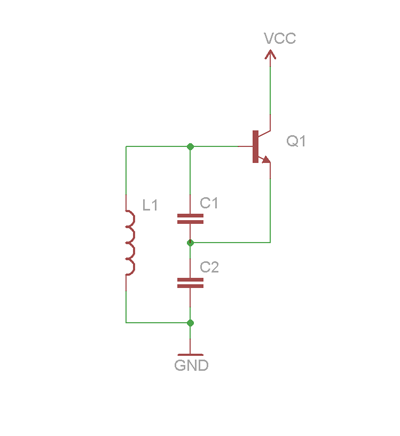 "Link2") with C1 and C2= 5.6pF, L=9.09x10^-5 (r=0.3m, a=3mm, N=6).
with C1 and C2= 5.6pF, L=9.09x10^-5 (r=0.3m, a=3mm, N=6).I have seen a lot people designing with low frequency(~1Mhz), but I'm aiming for a bigger transmission range. I have not decided which transistor I should use as I'm not familliar with Colpitts Oscillator and there's limited source out there.
Does anyone has any clue what kind of transistor should I be using to achieve a 10Mhz circuit? MOSFET has a limit of ~2Mhz that's why I've to look into Colpitts Oscillator.
Feel free to give me some suggestions or point out any difficulties I will be facing with this design as I'm still at the begining stage of the project.
Thanks :)
Re: Miniature wireless power demonstrator
Zxdave10, Wed Feb 02 2011, 05:44PM
Hello, Im doing a similiar project to marko and strider(more like strider). I used a network analyzer to discover the resonant freq of the coils. I am trying to use an impedence analyzer to find the characteristic impedance of each coil. Has anyone ever used empro to model wireless power? I am new to using empro and am having some issues.
Thanks
Re: Miniature wireless power demonstrator
epilot, Wed Feb 09 2011, 01:10PM
Hrello Marko,
Just have a question for you please.
I want to gather the stuff of your design (That's a really nice job thanks for sharing it) and make a such device.
But my question:
Is your circuit (shown at post NO 1) capable to lighten just 4 or 5 LED's at a distance of say 1 meter?
Thanks beforhands
Re: Miniature wireless power demonstrator
Monir, Thu Feb 10 2011, 06:12PM
Hello. In first place, congratulations Marko! It's a very nice project!! I want to develop the Marko project but have a doubt. What is the correct board that i use? Marko say that that the correct board is that have the relay but the date of this board is older than other. What i do?
Thanks
Re: Miniature wireless power demonstrator
Bix, Sat Feb 26 2011, 07:01AM
Hey Ive been following this project and am attempting to construct my own. Just wanted to gleam a few details:
The receiver side, what are the specs of the components? From what I see its just a parallel setup of a cap and an inductor, however what are the values of these? They are supposed to match the those of the transmitter ~ 54.4 nF? Were you able to find a capacitor close to this? And inductor would be at 200 uH?
Also in the final diagram there is an additional cap C12, what value is this?
Thanks.
Re: Miniature wireless power demonstrator
Marko, Sat Feb 26 2011, 08:19PM
Hi bix,
The L in the case of the receiver is a single loop as well, and C is indeed about the same as the transmitter. I used 47nF in my case, because the receiving loop was thinner conductor and had some more inductance than the transmitting loop (big 10cm pipe).
If you're out of tune you can place a ferrite core in one of loops and see where it helps. There's a ferrite core placed into the transmitter (prototype circuit in the second pic)
Marko
Re: Miniature wireless power demonstrator
TONY, Thu Mar 03 2011, 03:27PM
TONY, Thu Mar 03 2011, 03:27PM
Re: Miniature wireless power demonstrator
AstroBoy, Sun Mar 20 2011, 12:26AM
Marko,
Thank you, for the PM I can now search on my own for mosfets connected to their drains until I completely understand it…
Thanks again for sharing this project and I wish you much success with all of your future ventures…
AstroBoy, Sun Mar 20 2011, 12:26AM
Marko,
Thank you, for the PM I can now search on my own for mosfets connected to their drains until I completely understand it…
Thanks again for sharing this project and I wish you much success with all of your future ventures…
Re: Miniature wireless power demonstrator
lemta, Sun May 15 2011, 04:54PM
Hi Marko,
Can this system make a receiver with high current (such as 10A , 5-12v)?
lemta, Sun May 15 2011, 04:54PM
Hi Marko,
Can this system make a receiver with high current (such as 10A , 5-12v)?
Re: Miniature wireless power demonstrator
NoamS, Tue Aug 02 2011, 03:16PM
Hi Marko,
Firstly I would like to thank you for the design, its simple and elegant, just what I needed :)
But now I have a small problem: I'm trying to use your circuit to drive a the transmitter at a frequency of around 300kHz, but I'm having trouble setting the RFC's so that the circuit would work properly...
I am not really familiar with RF theory, but I'm guessing there is a way to calculate the correct value of the RFC.
Thank you
NoamS
Re: Miniature wireless power demonstrator
Eric.k, Mon Aug 22 2011, 08:44PM
Hello there,
Firstly, thanks very much for posting this up Marko, its excellent
Unfortunately, I am relatively new to creating my own electronics, and my schooling to date hasn't given me everything I need to complete it.
My questions are simple and noobish, but if anyone can help me I would greatly appreciate it.
1) Are RFC's directional, and if so, what is the appropriate way to solder them in/identify positive/negative terminals? and 2) on the mosfets, which 'legs' are the gate/drain/supply, so that I can connect it properly.
Thanks, and again sorry for the amateur questions.
I have added a picture of both to give context. thankyou

Re: Miniature wireless power demonstrator
Myke, Mon Aug 22 2011, 08:53PM
Welcome!
To answer your questions:
1. No. You can put them in any way.
2. What's the part number?
Myke, Mon Aug 22 2011, 08:53PM
Welcome!
To answer your questions:
1. No. You can put them in any way.
2. What's the part number?
Re: Miniature wireless power demonstrator
Eric.k, Mon Aug 22 2011, 11:56PM
Thanks for the quick reply Myke!
These are the ones I have here
EDIT: just realized my link did not work *fixed*
Eric.k, Mon Aug 22 2011, 11:56PM
Thanks for the quick reply Myke!
These are the ones I have here
EDIT: just realized my link did not work *fixed*
Re: Miniature wireless power demonstrator
MOSFET, Tue Sept 20 2011, 02:01PM
Thank Marko for sharing this nice project...
I tried to buil it and it worked just for a LED as load ... but in next time I tried it dosen't work ( in this case the power supply gives 1.5 A ... which mean that the transmitter is OK -as I think )
However I have some quastions about the theory..
How It works!! I mean How current flow?? how feedback achived by Diods??
I tried to make DC or Ac analysis but I faild !! can any one help me in this??
last quastion.. RFC why they are used??
Re: Miniature wireless power demonstrator
THOMAS18, Fri Dec 16 2011, 09:24AM
Hi, im very interested in this topic.
Is there any way marko, or some one who has done a similar project could post there
Final Circuit and component list?
This would be much appreciated.:-D
THOMAS18, Fri Dec 16 2011, 09:24AM
Hi, im very interested in this topic.
Is there any way marko, or some one who has done a similar project could post there
Final Circuit and component list?
This would be much appreciated.:-D
Re: Miniature wireless power demonstrator
Van Milby, Wed Jan 25 2012, 03:35PM
Hi guys is it possible to integrate a joule thief into the circuit for increased efficiency? Thanks! :D
Van Milby, Wed Jan 25 2012, 03:35PM
Hi guys is it possible to integrate a joule thief into the circuit for increased efficiency? Thanks! :D
Re: Miniature wireless power demonstrator
atayawa, Mon Feb 06 2012, 02:43PM
Hi Marko, thanks for sharing this awesome project!
Can you help me? What is the schematic diagram and parts for the Receiver side of the circuit. Thanks very much.
atayawa, Mon Feb 06 2012, 02:43PM
Hi Marko, thanks for sharing this awesome project!
Can you help me? What is the schematic diagram and parts for the Receiver side of the circuit. Thanks very much.
Re: Miniature wireless power demonstrator
zitlem, Sat Feb 11 2012, 11:28PM
Where can i find the latest schematic?
zitlem, Sat Feb 11 2012, 11:28PM
Where can i find the latest schematic?
Re: Miniature wireless power demonstrator
Amatek, Mon Mar 05 2012, 05:33AM
Hi everyone. I have been following this thread for quite some time now. I am writing a report on inductive wireless power transfer as my design part is already completed. I wanted to know:
What is the significance of the royer oscillator since the LC tank itself is an oscillator?
Re: Miniature wireless power demonstrator
Inducktion, Mon Mar 05 2012, 03:44PM
An LC tank alone is not an oscillator... It won't continue forever, as there's resistance in wires (not a lot, but enough) to kill of anything that may start.
The purpose of the royer is to keep the oscillations going even with the resistance by giving it positive gain to overcome the resistance effects.
Also, Marko, I've thought about it a little, and a one turn primary is bound to draw a lot of current, as there is very little impedance in your tank circuit. I've found that by adding more turns, you greatly decrease your current draw, and thus greatly decrease heating.
It's great if you want to make smaller versions of this circuit!
Re: Miniature wireless power demonstrator
Amatek, Tue Mar 06 2012, 12:35AM
Thanks for the reply.
And about adding more turns, apart from current and heating, would that affect any other thing?
Amatek, Tue Mar 06 2012, 12:35AM
Inducktion wrote ...
An LC tank alone is not an oscillator... It won't continue forever, as there's resistance in wires (not a lot, but enough) to kill of anything that may start.
The purpose of the royer is to keep the oscillations going even with the resistance by giving it positive gain to overcome the resistance effects.
Also, Marko, I've thought about it a little, and a one turn primary is bound to draw a lot of current, as there is very little impedance in your tank circuit. I've found that by adding more turns, you greatly decrease your current draw, and thus greatly decrease heating.
It's great if you want to make smaller versions of this circuit!
Thanks for the reply.
And about adding more turns, apart from current and heating, would that affect any other thing?
Re: Miniature wireless power demonstrator
Inducktion, Tue Mar 06 2012, 01:05AM
Lower the frequency, decreased output power, etc
Inducktion, Tue Mar 06 2012, 01:05AM
Lower the frequency, decreased output power, etc
Re: Miniature wireless power demonstrator
Amatek, Tue Mar 06 2012, 01:44AM
How about the diameter of the coils? What are the effects?
Amatek, Tue Mar 06 2012, 01:44AM
Inducktion wrote ...
Lower the frequency, decreased output power, etc
Lower the frequency, decreased output power, etc
How about the diameter of the coils? What are the effects?
Re: Miniature wireless power demonstrator
Amatek, Wed Mar 07 2012, 04:21AM
And one more thing. How can I measure the frequency with an oscilloscope? Thanks.
Amatek, Wed Mar 07 2012, 04:21AM
And one more thing. How can I measure the frequency with an oscilloscope? Thanks.
Re: Miniature wireless power demonstrator
m4ge123, Wed Mar 07 2012, 06:27AM
Scope the tank voltage.
m4ge123, Wed Mar 07 2012, 06:27AM
Scope the tank voltage.
Re: Miniature wireless power demonstrator
THOMAS18, Mon Mar 26 2012, 09:52AM
Does anyone know the Resistor value of R7 and R6 in the latest Schematic? i assume the rest are as previous schematic.
Thank you
THOMAS18, Mon Mar 26 2012, 09:52AM
Does anyone know the Resistor value of R7 and R6 in the latest Schematic? i assume the rest are as previous schematic.
Thank you
Re: Miniature wireless power demonstrator
Amatek, Tue Mar 27 2012, 05:37PM
I am getting confused around this stage. What exactly are the 'hot' ends of the LC tank?
Amatek, Tue Mar 27 2012, 05:37PM
Marko wrote ...
20. 04. 2010 - update:
3. Try measuring the LC tank voltage with an oscilloscope, not a frequency counter - this also has to show the peak voltage which has to be about pi*supply voltage (37V for 12V supply). Some precautions are required while doing this - the power supply must not have grounded " - " (like a PC power supply does) because placing an oscilloscope ground clip to one of 'hot' ends of LC tank will cause short circuit. In that case we need to measure with scope input set to DC input and measure between ground and one ''hot end''. This will yield a ''halfwave rectified'' waveform but the peak voltage value should remain the same.
Cheers,
Marko
I am getting confused around this stage. What exactly are the 'hot' ends of the LC tank?
Re: Miniature wireless power demonstrator
mister_rf, Wed Apr 18 2012, 01:08PM
I have tested this circuit and it works very well.
In use :
-STP60NF10 power MOSFET transistors
-diodes: SR810 (100V/8A) and STTH3R02.
-Rg = 68 ohms/3W , but later increased to 100 ohms /2W
-Radio frequency chokes ~ 150uH.
You can see the results here:

mister_rf, Wed Apr 18 2012, 01:08PM
I have tested this circuit and it works very well.
In use :
-STP60NF10 power MOSFET transistors
-diodes: SR810 (100V/8A) and STTH3R02.
-Rg = 68 ohms/3W , but later increased to 100 ohms /2W
-Radio frequency chokes ~ 150uH.
You can see the results here:

Re: Miniature wireless power demonstrator
Conundrum, Wed Apr 18 2012, 07:16PM
Wonder if you could power a Lifter wirelessly?
That would be interesting to see working.
-A
Conundrum, Wed Apr 18 2012, 07:16PM
Wonder if you could power a Lifter wirelessly?
That would be interesting to see working.
-A
Re: Miniature wireless power demonstrator
KrystaL, Sun Apr 22 2012, 12:29PM
Hello guys , i want to ask can we use 1.6MHz oscillator , and amplify its amplitude to that level , becoz these compionents are not easily available in my area
KrystaL, Sun Apr 22 2012, 12:29PM
mister_rf wrote ...
I have tested this circuit and it works very well.
In use :
-STP60NF10 power MOSFET transistors
-diodes: SR810 (100V/8A) and STTH3R02.
-Rg = 68 ohms/3W , but later increased to 100 ohms /2W
-Radio frequency chokes ~ 150uH.
You can see the results here:
I have tested this circuit and it works very well.
In use :
-STP60NF10 power MOSFET transistors
-diodes: SR810 (100V/8A) and STTH3R02.
-Rg = 68 ohms/3W , but later increased to 100 ohms /2W
-Radio frequency chokes ~ 150uH.
You can see the results here:
Hello guys , i want to ask can we use 1.6MHz oscillator , and amplify its amplitude to that level , becoz these compionents are not easily available in my area
Re: Miniature wireless power demonstrator
THOMAS18, Mon Apr 23 2012, 01:57PM
Hi, has any one powered a 12v pc fan ? Iv been working on my receiver quite abit on different loads but even a small 12vdc 0.18amp fan doesn't want to work?
Any suggestions ?
Thanks alot
THOMAS18, Mon Apr 23 2012, 01:57PM
Hi, has any one powered a 12v pc fan ? Iv been working on my receiver quite abit on different loads but even a small 12vdc 0.18amp fan doesn't want to work?
Any suggestions ?
Thanks alot
Re: Miniature wireless power demonstrator
mister_rf, Mon Apr 23 2012, 05:07PM
In order to power up a small DC fan you need to use a rectifier bridge.
The purpose of the rectifier section is to convert the incoming alternating current from the AC power source to some form of pulsating DC.
By the way, at this high frequencies some schottky diodes need to be used for.
For example I have managed to modify a small mobile phone in order to be recharged wirelessly form the Royer oscillator. See a video here:
Re: Miniature wireless power demonstrator
Pankaj Patel, Mon Apr 23 2012, 05:55PM
Check out the demo by ewipower
Wireless power demonstration
Wireless mobile charging
Very soon i will update the schematic for this projects
Pankaj Patel, Mon Apr 23 2012, 05:55PM
Check out the demo by ewipower
Wireless power demonstration
Wireless mobile charging
Very soon i will update the schematic for this projects
Re: Miniature wireless power demonstrator
mister_rf, Tue Apr 24 2012, 11:29AM
However, try to use other types of transistors. I have managed to test in circuit various MOSFET transistors. (Empirical tests only, not claim to scientific value. )
The initial setup:
• Vcc = 12V
• Rg = 100 ohms (R1, R2)
• Diode D1,D2 = STTH3R02 -ultrafast 200V/3A
• DiodeD3, D4 = SR810 schottky 100V/8A
• L = 1 turn/ 210 mm diameter/13 mm Copper tube
• capacitor C = 22nF/ FKP type 1000V
I have measured for each transistor:
•current consumption without external load = ' Io'
•the on load current = 'Is' ,(for a 50 mm clearance between transmitter and receiver coils).
•the maximum distance for light bulb filament still glowing => 'dmax'
And the results:
1. IRF520NPBF N-Ch 100V 9,7A 48W 0,20R TO220AB (• Turn-On Delay Time: 4.5ns • Turn-Off Delay Time: 32ns)
Io = 0.38A, Is = 0.78A, dmax= 490mm
2. IRF530PBF N-Ch 100V 14A 88W 0,16R TO220AB(• Turn-On Delay Time: 10ns • Turn-Off Delay Time: 23ns)
Io = 0.42A, Is = 0.85A, dmax= 470mm
3. IRF540NPBF N-Ch 100V 33A 130W 0,044R TO220A (• Turn-On Delay Time: 11ns• Turn-Off Delay Time: 39ns)
Io = 0.48A, Is = 0.95A, dmax= 470mm
4. IRF630PBF N-Ch 200V 9A 74W 0,4R TO220AB (• Turn-On Delay Time: 9.4ns• Turn-Off Delay Time: 39ns)
Io = 0.4A, Is = 0.85A, dmax= 470mm
5. IRF640NPB N-Ch 200V 18A 150W 0,15R TO220AB (• Turn-On Delay Time: 10ns • Turn-Off Delay Time: 23ns)
Io = 0.44A, Is = 0.9A, dmax= 460mm
6. IRF740PBF N-Ch 400V 10A 125W 0,55R TO220AB (• Turn-On Delay Time: 14ns • Turn-Off Delay Time: 50ns)
Io = 0.46A, Is = 0.92A, dmax= 450mm
7. IRF3808 N-Ch 75V 140A 330W 0,007R TO220AB
No results for the actual setup circuit…
• Next, the power supply voltage tests.
I have kept one pair of IRF520 on place, then start increasing the power supply voltage up to 30V. Maximum distance for the 12V/5W load (light bulb steady on condition) has increase up to 750mm, and the 'no load current' increase up to 0.8A. The only problem Rg=100 ohms went on fire!... By the other hand the minimum required voltage for the power supply: 7V-7.5V.
• The 'Rg' resistor test ('R1' and 'R2' in the actual schematic)
I have keep the original circuit configuration (IRF520, Vcc= 12V), and I have managed to increase 'Rg' value up to 720 ohms for a 'no load current' =0.23A. Finally all the IRF 520/530/540/630/640 and 740 transistors do the job using a 680 ohms (0.25W) standard resistor value.
• The diode test.
I have run some test for the diodes used to discharge the MOSFET gates, same setup circuit IRF520, Vcc=12V and Rg= 680 ohms.
The following diodes types were tested
- STTH3R02, those are running very cool, Io= 0.23A
- 1N4148. Not all the diodes I have tested can manage the situation OK, some are very hot, some were destroyed and 'Io' (the 'no load current') increase up to 0.35A
- MBRS1100T3G, running cool, 'Io' = 0.25A
- BA157, BA159 series, running OK, just a little warmer, 'Io'= 0.35A
- BYV27, running cool, 'Io' = 0.28A
And my final conclusion for these tests:
at 12V power supply we get perfect results using any of the transistors and diodes mentioned above. This allow to increase the 'Rg' resistors value and hence reducing power losses in resistors.
In any situation need to use always some very good capacitors, as the recommended FKS/FKP/MKS or MKP foil polyester series.
mister_rf, Tue Apr 24 2012, 11:29AM
KrystaL wrote ...
Hello guys , i want to ask can we use 1.6MHz oscillator , and amplify its amplitude to that level , becoz these compionents are not easily available in my area
No, that's more complicated solution than the original version.Hello guys , i want to ask can we use 1.6MHz oscillator , and amplify its amplitude to that level , becoz these compionents are not easily available in my area
However, try to use other types of transistors. I have managed to test in circuit various MOSFET transistors. (Empirical tests only, not claim to scientific value.
)The initial setup:
• Vcc = 12V
• Rg = 100 ohms (R1, R2)
• Diode D1,D2 = STTH3R02 -ultrafast 200V/3A
• DiodeD3, D4 = SR810 schottky 100V/8A
• L = 1 turn/ 210 mm diameter/13 mm Copper tube
• capacitor C = 22nF/ FKP type 1000V
I have measured for each transistor:
•current consumption without external load = ' Io'
•the on load current = 'Is' ,(for a 50 mm clearance between transmitter and receiver coils).
•the maximum distance for light bulb filament still glowing => 'dmax'
And the results:
1. IRF520NPBF N-Ch 100V 9,7A 48W 0,20R TO220AB (• Turn-On Delay Time: 4.5ns • Turn-Off Delay Time: 32ns)
Io = 0.38A, Is = 0.78A, dmax= 490mm
2. IRF530PBF N-Ch 100V 14A 88W 0,16R TO220AB(• Turn-On Delay Time: 10ns • Turn-Off Delay Time: 23ns)
Io = 0.42A, Is = 0.85A, dmax= 470mm
3. IRF540NPBF N-Ch 100V 33A 130W 0,044R TO220A (• Turn-On Delay Time: 11ns• Turn-Off Delay Time: 39ns)
Io = 0.48A, Is = 0.95A, dmax= 470mm
4. IRF630PBF N-Ch 200V 9A 74W 0,4R TO220AB (• Turn-On Delay Time: 9.4ns• Turn-Off Delay Time: 39ns)
Io = 0.4A, Is = 0.85A, dmax= 470mm
5. IRF640NPB N-Ch 200V 18A 150W 0,15R TO220AB (• Turn-On Delay Time: 10ns • Turn-Off Delay Time: 23ns)
Io = 0.44A, Is = 0.9A, dmax= 460mm
6. IRF740PBF N-Ch 400V 10A 125W 0,55R TO220AB (• Turn-On Delay Time: 14ns • Turn-Off Delay Time: 50ns)
Io = 0.46A, Is = 0.92A, dmax= 450mm
7. IRF3808 N-Ch 75V 140A 330W 0,007R TO220AB
No results for the actual setup circuit…
• Next, the power supply voltage tests.
I have kept one pair of IRF520 on place, then start increasing the power supply voltage up to 30V. Maximum distance for the 12V/5W load (light bulb steady on condition) has increase up to 750mm, and the 'no load current' increase up to 0.8A. The only problem Rg=100 ohms went on fire!...
By the other hand the minimum required voltage for the power supply: 7V-7.5V.• The 'Rg' resistor test ('R1' and 'R2' in the actual schematic)
I have keep the original circuit configuration (IRF520, Vcc= 12V), and I have managed to increase 'Rg' value up to 720 ohms for a 'no load current' =0.23A. Finally all the IRF 520/530/540/630/640 and 740 transistors do the job using a 680 ohms (0.25W) standard resistor value.
• The diode test.
I have run some test for the diodes used to discharge the MOSFET gates, same setup circuit IRF520, Vcc=12V and Rg= 680 ohms.
The following diodes types were tested
- STTH3R02, those are running very cool, Io= 0.23A
- 1N4148. Not all the diodes I have tested can manage the situation OK, some are very hot, some were destroyed and 'Io' (the 'no load current') increase up to 0.35A
- MBRS1100T3G, running cool, 'Io' = 0.25A
- BA157, BA159 series, running OK, just a little warmer, 'Io'= 0.35A
- BYV27, running cool, 'Io' = 0.28A
And my final conclusion for these tests:
at 12V power supply we get perfect results using any of the transistors and diodes mentioned above. This allow to increase the 'Rg' resistors value and hence reducing power losses in resistors.
In any situation need to use always some very good capacitors, as the recommended FKS/FKP/MKS or MKP foil polyester series.
Re: Miniature wireless power demonstrator
THOMAS18, Tue Apr 24 2012, 01:06PM
THOMAS18, Tue Apr 24 2012, 01:06PM
mister_rf wrote ...
In order to power up a small DC fan you need to use a rectifier bridge.
The purpose of the rectifier section is to convert the incoming alternating current from the AC power source to some form of pulsating DC.
By the way, at this high frequencies some schottky diodes need to be used for.
For example I have managed to modify a small mobile phone in order to be recharged wirelessly form the Royer oscillator. See a video here:
I have a few of these laying around:
BYW29-200-E3/45 - Ultrafast Rectifier Diode
are Schottky Diodes essential in this application. Im guessing the slight amound of stored charge will delay a standard diode and create alot of head.
Thanks alot
Re: Miniature wireless power demonstrator
mister_rf, Tue Apr 24 2012, 01:36PM
Pretty fast diodes, you should give it a try.
mister_rf, Tue Apr 24 2012, 01:36PM
Pretty fast diodes, you should give it a try.
Re: Miniature wireless power demonstrator
Forty, Tue Apr 24 2012, 04:20PM
very nice data mister rf.
So basically everyone can change their resistor value to save a little power and not have it affect the results. pretty useful. I'm also surprised that such different mosfets yielded approximately the same results. One question though: what was your power supply and was it current limited?
Re: Miniature wireless power demonstrator
mister_rf, Tue Apr 24 2012, 09:25PM
For the initial tests I have used a variable regulated power supply, 0-30V output, 3A current limiting.
Later I have used a 12V/2A power supply. (But you can use almost any 10-15V/1A power supply for this purpose).
mister_rf, Tue Apr 24 2012, 09:25PM
For the initial tests I have used a variable regulated power supply, 0-30V output, 3A current limiting.
Later I have used a 12V/2A power supply. (But you can use almost any 10-15V/1A power supply for this purpose).
Re: Miniature wireless power demonstrator
radhoo, Mon Apr 30 2012, 11:40AM
The idea is to use a modified battery that also includes a small receiver coil, a capacitor and a fast rectifier.
radhoo, Mon Apr 30 2012, 11:40AM
mister_rf wrote ...
In order to power up a small DC fan you need to use a rectifier bridge.
The purpose of the rectifier section is to convert the incoming alternating current from the AC power source to some form of pulsating DC.
By the way, at this high frequencies some schottky diodes need to be used for.
For example I have managed to modify a small mobile phone in order to be recharged wirelessly form the Royer oscillator. See a video here:
Yes but you still use a wire connected to the phone, so why not plug it to the wall directly?In order to power up a small DC fan you need to use a rectifier bridge.
The purpose of the rectifier section is to convert the incoming alternating current from the AC power source to some form of pulsating DC.
By the way, at this high frequencies some schottky diodes need to be used for.
For example I have managed to modify a small mobile phone in order to be recharged wirelessly form the Royer oscillator. See a video here:
The idea is to use a modified battery that also includes a small receiver coil, a capacitor and a fast rectifier.
Re: Miniature wireless power demonstrator
mister_rf, Tue May 01 2012, 08:12AM
There are no wires outside the phone. That’s a wireless charger.
All items were included in the phone case = receiver coil + capacitor + schottky bridge rectifiers + 5V step-down converter (LM2678-5).
There’s only one major problem, because of the circuit high frequency (~1.6MHz) you need to place the receiver coil (that it’s inside phone case) very near to the transmitter coil.

Re: Miniature wireless power demonstrator
radhoo, Wed May 02 2012, 08:50PM
In this case, congrats, you've got a compact wireless charger! Would love to see some pics of the inside of the phone.
radhoo, Wed May 02 2012, 08:50PM
In this case, congrats, you've got a compact wireless charger! Would love to see some pics of the inside of the phone.
Re: Miniature wireless power demonstrator
mister_rf, Thu May 03 2012, 06:52AM
Need to mention this sort of experiment was not properly prepared at that time.
Normally, to get the best results, we may first try to adapt some sort of LC antenna into the phone case and second step to modify the transmitter frequency to match the receiver one. Otherwise it’s time consuming just finding proper capacitors to boost more energy.
Here are some phone pictures, (you can see this was not prepared for marketing ).
First a dc-dc converter assembly was squeezed in the place of the old speaker (no PCB, just wired on place, and the old speaker replaced by a smaller one).
Second, a picture of the first coil I have made the initial receiving tests.
And the last one, a picture of the new antenna made of some copper foil.


mister_rf, Thu May 03 2012, 06:52AM
Need to mention this sort of experiment was not properly prepared at that time.
Normally, to get the best results, we may first try to adapt some sort of LC antenna into the phone case and second step to modify the transmitter frequency to match the receiver one. Otherwise it’s time consuming just finding proper capacitors to boost more energy.
Here are some phone pictures, (you can see this was not prepared for marketing
).First a dc-dc converter assembly was squeezed in the place of the old speaker (no PCB, just wired on place, and the old speaker replaced by a smaller one).
Second, a picture of the first coil I have made the initial receiving tests.
And the last one, a picture of the new antenna made of some copper foil.


Re: Miniature wireless power demonstrator
Monir, Mon May 07 2012, 06:52PM
Did you used on the video project the 12 relay and the capacitor C7? This itens are on the schematic but I 'cant find it on the video.
Thanks
Monir, Mon May 07 2012, 06:52PM
mister_rf wrote ...
I have tested this circuit and it works very well.
In use :
-STP60NF10 power MOSFET transistors
-diodes: SR810 (100V/8A) and STTH3R02.
-Rg = 68 ohms/3W , but later increased to 100 ohms /2W
-Radio frequency chokes ~ 150uH.
You can see the results here:
I have tested this circuit and it works very well.
In use :
-STP60NF10 power MOSFET transistors
-diodes: SR810 (100V/8A) and STTH3R02.
-Rg = 68 ohms/3W , but later increased to 100 ohms /2W
-Radio frequency chokes ~ 150uH.
You can see the results here:
Did you used on the video project the 12 relay and the capacitor C7? This itens are on the schematic but I 'cant find it on the video.
Thanks
Re: Miniature wireless power demonstrator
mister_rf, Mon May 07 2012, 10:16PM
There was no relay at that time and the circuit was triggered by using a simple switch, but later I had to use one in order to simplify the start-up procedure.
About the capacitor, there are actually two pieces hidden there (close to the power supply terminal blocks), see the picture:

Re: Miniature wireless power demonstrator
Monir, Wed May 09 2012, 02:57PM
Hello Mister_rf
Thank for help me!
Did you try to simulate the circuit in a software?
Is this C7 the little gray capacitor, isn't?
[]'s
Monir, Wed May 09 2012, 02:57PM
Hello Mister_rf
Thank for help me!
Did you try to simulate the circuit in a software?
Is this C7 the little gray capacitor, isn't?
[]'s
Re: Miniature wireless power demonstrator
E3, Tue Jun 05 2012, 12:10PM
Hello everybody,
My native language is not English, so I apologize for my mistake
Primarily, Marko, I want to say thank you very much for this project. I'm electrical & electronics engineering student. I made this project, wireless energy transfer, for my electromagnetic field theory lesson and I attached these photos. Transmitter circuit frequency is approximate 1 Mhz and I measured 15-20 cm transfer distance. Maybe in the future I would like to promote this project. Thanks everybody and Marko.
Best regards.


Re: Miniature wireless power demonstrator
Crozatti, Sat Aug 25 2012, 03:30PM
Hey guys,
First of all, thanks for Marko for this great project, it really works and it's very detailed making the possibility for a layman like me construct the project. Thanks!
Now, I'm going to step 2, construct the wireless mobile charger, with the help of the detailed post of mister_rf.
Thanks for all guys, you're really great!
Re: Miniature wireless power demonstrator
wops, Thu Nov 08 2012, 10:49PM
Hello everyone,
First thank you all very much for posting and sharing your knowledge about wireless energy it is really nice to get so much informations from one thread !! Thank you especially marko for all your work.
I'm trying to make your circuit, the one with the new PCB, I can't wait for my components to arrive because I'm really excited to start the experiments !
One question though, I tried to make a simulation of the circuit on LT SPICE IV, it seemed that it worked but my question is, does it fit reality and especially what you saw during your experiment ?
Here are the circuit on lt spice, and the current in the inductor L3 from the tank
One more question, how did you chose the value of the choke ? why 100micro and not more or less ?
thanks !
--
Wops


Re: Miniature wireless power demonstrator
Sulaiman, Fri Nov 09 2012, 01:31PM
MISTER RF .... is that really how you connected the relay?
I would expect the gate drive on before the dc to the inductor(s).
Sulaiman, Fri Nov 09 2012, 01:31PM
MISTER RF .... is that really how you connected the relay?
I would expect the gate drive on before the dc to the inductor(s).
Re: Miniature wireless power demonstrator
Crozatti, Sat Dec 08 2012, 07:29PM
Hi guys,
I finished my project with a junction of marko and mister_rf schamatics, and the results is charger a phone over 25cm with full power.
I believe that is a great result, but, I have a little and important doubt...
How I calculate the inductance of inductive magnetic coupling? I mean, the "antenna"?
Can anyone help me?
Thank you
Re: Miniature wireless power demonstrator
zero_coke, Fri Mar 08 2013, 05:22AM
Hi Marko,
Great experiment! I have a few questions of my own if you could please answer:
1) We are planning on using separate modules do the oscillating and power amplification. How come you are using a Royer Oscillator instead of using a signal generator + a Power Amplifier? I understand Power Amplifiers are lossy but class E and class F oscillators work well in high frequencies and are efficient. Can you tell me why please.
2) When I'm out looking for capacitors, what ratings should I be looking for? I noticed you used the WIMA FKP1 series and about 8 of them in parallel. Is the reason you have 8 because you want to distribute the power amongst the capacitors? If so, what ratings of voltage should I get them in and how many should I use?
3) When you were pumping out ~20A into your coil, did you measure the H and E field around your coil? I'm asking this because safety standards dictate a maximum field strength of ~5 A/m from 0-1MHz and about ~5/f from 1-10 MHz where f is in MHz. I'm wondering because this sort of limits how much current you can pump out into your driving coil. We calculated a maximum current of 2.8A for our coils to be below this field strength. Can you please verify this.
4) Is there an advantage in using a 4 coil system whereby your transmitting coil is inductively coupled to your source coil? I noticed some people did this and it improves their resonator Q and increases the overall efficiency of the system but I don't know exactly why. I know that by having an extra coil in the middle you can refer impedances back and forth depending on the # of turns you have setup but when these coils are so far apart can you even refer the impedance of your load coils which are like 30cm+ away from your transmitter to your primary coil? I don't think things work like the transformer action way at such low coupling. I dont know if the formula exists for referring impedances with non-unity coupling coefficient values.
5) Thanks man :)
Re: Miniature wireless power demonstrator
Marko, Sat Mar 09 2013, 01:18PM
Hello everyone! Glad to see so many people still being interested in this project that dates from my high school days. I'm now actually approaching the end of my college studies and am having only less and less time to teach about things like these. However I have some time right now so I'll try to answer a few good questions here.
zero_coke:
1. - It's absolutely possible to use a fixed frequency signal source and a class E or similar amplifier to feed the transmitting circuit, and could easily be more efficient than the Royer oscillator (especially the crappy version presented in this thread, I haven't been using that for a long time now!). However, the fixed signal source would mean you now have two degrees of tuning instead of one which greatly complicates the tuning process. If your system is moved around or intended to be used in a serious application the resonant frequencies of the resonators will certainly change and you'd have to readjust both the resonators mutually, as well as the signal source. Royer oscillator always drives the transmitting resonator at resonance, so only one degree of tuning is necessary. Bonus for you if you can make the receiver self-tuning too!
For any serious application, I'd make sure that at least the primary side is self resonant no matter what topology is used. For really high power I'd probably favor a series resonant half bridge class DE amplifier with PLL or similar feedback. However, one must note another advantage of royer oscillator - unlike most other topologies, it always keeps the tank circuit voltage constant. Series resonant on the other hand would ring up without load and would need an extra control loop to prevent it from blowing itself up if it's Q is allowed to go too high.
2. I used 8 parallel capacitors to distribute the fairly heavy tank current among them. For a higher power design the number of capacitors could easily get impractical - in this case it would be a good idea to switch towards conduction cooled capacitors such as used for induction heating.
In royer oscillator, the capacitors see pi*supply voltage peak. I used overrated 1000V caps to get more surface area for cooling, and because I had them at hand after all.
3.Well, I don't have any equipment that I can use to accurately measure H at RF frequencies - though inside the coil it can be estimated as H = I/D where D is diameter of the loop... so in this case its about 200A/m for a 10cm coil. I figured any such rules are silly, so I ignored them; induction heaters can produce 2-3 orders of magnitude greater H in vicinity of their coils and yet no laws seem to prevent them from being produced and used. You can't do anything about laws of physics here!
I'd only be concerned that stray radiation that could disrupt radio communications, so I'd probably chose some ISM band frequency like 6.775, 13.55 Mhz or such. Note that is a double edged blade, as it would enable your wireless transmitter to resonate and fry some RFID and radio devices operating at these frequencies. So you might just chose a frequency low enough to assure that your system doesn't get to radiate significant power as radio waves.
4. "4 coil" system is really nothing but a method of feeding power into and out of resonators. You could also do it directly by series or parallel feeding, as well as use a ferrite transformer for insulation if necessary. If your resonators are Tesla coils they become such high impedance that it's practical to feed power by capacitive means as well!
You're probably referring to MIT experiment where resonators were free coils that had single loop coils near them to feed power in and out. The resonators likely had kilovolts on them and were rather impractical to be fed directly by a vacuum tube oscillator, or to drive a light bulb directly, so the air core step-up and step-down transformers were required.
On the other hand, I loaded my single-turn copper loop with a big capacitor which makes it's impedance so low that it can transfer fun amounts of power with as little as 50V input.
Q of the resonators doesn't really have much to do with this - it's all about losses in copper and capacitor dielectric in the resonator (if capacitors are present, of course).
Marko
Re: Miniature wireless power demonstrator
zero_coke, Sat Mar 09 2013, 08:41PM
You are awesome man! Thanks for taking the time to answer the questions. I have some pictures to show you and a few more questions if you have the time please.
First is the signal generator we bought to generate a signal at some particular frequency:
https://www.dropbox.com/s/wprrxo55gxjzfuu/oscillator%20-%20top%20view.jpg
Next is the pre-stage amplifier (5W output) needed to drive our main amplifier:
https://www.dropbox.com/s/skcmh1s361oui2y/pre-amplifier%20-%20top%20view.jpg
And finally this is our main amplifier (140W):
https://www.dropbox.com/s/t7paoiugywegm4d/amplifier%20-%20top%20view.jpg?
And then we have our coils which are 1 turn, 10 turns, 10 turns, and 1 turn, respectively. The first two coils are inductively coupled which is on the transmitting end and the last two are inductively coupled on the receiving end. The middle two are resonant coupled. The first two coils are copper pipe, and the last two coils are just copper wire (not thin wire or anything, just a
I have a few questions now that I'd like to ask:
1 - We couldn't find any reason to pick a high frequency or low frequency for our resonant frequency for this application. According to our simulations it seems like lower frequencies give better performance in terms of power input and power output, but I'm still not convinced as to why even though the numbers dictate. Wouldn't using higher frequencies be more efficient? I always thought that operating at higher frequencies would increase efficiency of the system.
2 - I noticed that you said you had 1 capacitor in the transmitting end. Can you tell me again why you had just 1 instead of multiple capacitors?
3 - Can you please tell me again how the resonant frequency will change in my setup as compared to the royer oscillator setup? So are you saying that by moving the receiver closer/away from the transmitter I will need to re-adjust my resonant frequency? I just need a little more explaining if you don't mind sorry. I don't know why the resonant frequency will change if I move the receiver. By the way, our load is going to be either a light bulb or a fan so that might not be a problem in this setup would it?
4 - Do we need to match the output impedance of our amplifier to the coils? I mean, the amplifier is rated for 140W into a 50 Ohm load, so do we need to make sure that the coil at its resonant frequency has an impedance of 50 Ohms? I'm assuming if you have this setup, maximum power will be delivered to the driving coil right? What if our coil does not have 50 Ohms, do we just add a series resistor to match it?
5 -Do you have any recommendation for us? Right now we have a signal generator connected to an amplifier and that amplifier is connected to our main driving coil. It's basically as simple as that. We're hoping that with about 100W input into our main transmitting coil, we can get about 20-30W at the output. Does this seem feasible to you?
Thanks very much Marko and friends!
Re: Miniature wireless power demonstrator
Marko, Tue Mar 12 2013, 10:37PM
Hi
From purely theoretical point of view, the only thing that really matters is the Q factor of the resonators; the frequency itself is irrelevant. But, low frequency will result in too big reactive components, and too high frequency will increase losses due to skin effect, as well as make the system radiate more spurious radio waves.
Looking at your amplifier, to me it looks like a radio transmitter amp designed to drive a 50 ohm resistive load at a certain frequency. Both impedance and resonant frequencies will change if you alter the coupling between resonators or change the load, so a setup like this is best suited for static demonstrations with fixed resonator distance and a light bulb as a load.
While RF amplifier will probably tolerate some reflected power, it can't be guaranteed not to blow up if it has no protection circuits installed.
When resonators are weakly coupled, both modes of the system will be very near the free resonant frequencies of each resonator alone, so you'd probably want to tune up for that.
The feeder loop that is coupled to the transmitting resonator forms an air cored transformer that performs impedance matching to the amplifier. Inverse is done on the receiver side in order to match into the light or whatever other load. A right way to design it would be to simulate the whole system in a FEMM software and wind the exact required coupling and number of turns for your feeder coil/loop.Note that this kind of coupling will always present some inductive reactance to the amplifier due to low magnetizing inductance of the loop, adding to amplifier unhappiness.
I think Steve Conner had some success with a setup like this, where he used his HAM amplifier to drive the power into system. I'm not sure how much can I help without knowing more details about the amplifier!
Regarding the cap in my receiver, I just used one because reactive power was lower there than on the transmitter (since it's only weakly coupled most of the time) and it seemed to be enough. If your resonators will be placed at cl0ose distance for high power transfer, you'd probably want identical cap banks in both of them.
Marko
Re: Miniature wireless power demonstrator
zero_coke, Wed Mar 13 2013, 06:41PM
Thanks very much Marko!
Yeah I think I just destroyed my power amplifier...it is a radio transmitter power amp so I probably screwed up somewhere but I don't know where...I simply connected it to the load and made sure the impedance of my transmitting coil was 50 ohms by adding a series resistor to top up the impedance of the coil to a total of 50 ohms.
I don't think it has to do with reflected power because I'm not at high enough frequencies for such phenomena of reflections to occur right? I'm at 2 MHz so lambda = 150 m and lambda / 40 = 3.75m (general rule for circuit size vs reflections, correct me if I'm wrong) and my circuit is definitely smaller than 3.75m so I don't think I have to worry about microwave phenomena here...or do I ?
I contacted Steve Conner to see how he used the ham radio amplifier in this setup. I thought it'd be straightforward but I guess not...
Re: Miniature wireless power demonstrator
electronics-PCB, Thu Mar 28 2013, 06:32PM
Hello everybody!
First of all: thank you Marko for sharing this work and for starting this thread.
I did a small demo and videod it at my job/firm. I tried to decent and thank Marko and you all at the end of the video...
If interested you can find the video here:
Basic lightbulb demo, but I experimented with ferromagnetic toroids at the final part of the video.
This would be fun to continue, because I simulated versions of the project with over a 40% efficiency....lets see if I can get the funds + time for this sometime.
Cheers, esa
Re: Miniature wireless power demonstrator
Ynicky, Sat Apr 20 2013, 09:46AM
Hi all!
This is my version of Marko's project.
Ynicky, Sat Apr 20 2013, 09:46AM
Hi all!
This is my version of Marko's project.
Re: Miniature wireless power demonstrator
Veronica P., Mon May 20 2013, 01:48AM
Hi there,
I'm trying to recreate Marko's circuit, but it doesn't work. I also used different inductors. I used 100u, then 150u and 200. There was a LOT of smoking and popping. Can anyone explain why that happened?
Veronica P., Mon May 20 2013, 01:48AM
Hi there,
I'm trying to recreate Marko's circuit, but it doesn't work. I also used different inductors. I used 100u, then 150u and 200. There was a LOT of smoking and popping. Can anyone explain why that happened?
Re: Miniature wireless power demonstrator
Ynicky, Tue May 21 2013, 03:36PM
To Veronica:
What has burned? Inductors, MOSFETs or relay?
What type of MOSFETs?
Have D1, D2 right connection?
What capacitance have C1...C8?
Ynicky, Tue May 21 2013, 03:36PM
To Veronica:
What has burned? Inductors, MOSFETs or relay?
What type of MOSFETs?
Have D1, D2 right connection?
What capacitance have C1...C8?
Re: Miniature wireless power demonstrator
Veronica P., Sun May 26 2013, 07:02AM
Ynicky,
I've managed to fix the problem,
The inductors had burned. The MOSFETS are the ones Marko outlined- IRFZ44N, the capacitors were also all 6.8uF, with one being 100nF.
The problem was I was substituting one 47uF capacitor for the smaller ones, and one of my resistors was not the correct value.
Re: Miniature wireless power demonstrator
Veronica P., Sat Jun 01 2013, 05:12AM
Hi,
Has anyone done a circuit analysis of their wireless power transfer circuits? Which equations are the best to focus on?
(I mean to look at the characteristics of the circuit)
Veronica P., Sat Jun 01 2013, 05:12AM
Hi,
Has anyone done a circuit analysis of their wireless power transfer circuits? Which equations are the best to focus on?
(I mean to look at the characteristics of the circuit)
Re: Miniature wireless power demonstrator
jechwa, Fri Aug 30 2013, 02:31PM
Hi,
I build Markos transmitter and did some experiments. I found that it is possible to increase the transfer distance using passive LC tank circuits.
At the moment I reach a distance seven times the coil diameter of the Rx coil: 70cm.
See my youtube video:
http://www.youtube.com/channel/UCP6EEu4DG22gg-6l0L4ATJA
cheers
Jens
Re: Miniature wireless power demonstrator
jechwa, Fri Aug 30 2013, 02:42PM
6.8 µF, 47µF are to high! You mean nF ?
jechwa, Fri Aug 30 2013, 02:42PM
Veronica P. wrote ...
Ynicky,
I've managed to fix the problem,
The inductors had burned. The MOSFETS are the ones Marko outlined- IRFZ44N, the capacitors were also all 6.8uF, with one being 100nF.
The problem was I was substituting one 47uF capacitor for the smaller ones, and one of my resistors was not the correct value.
6.8 µF, 47µF are to high! You mean nF ?
Re: Miniature wireless power demonstrator
ARB, Sat Aug 31 2013, 06:35AM
Greetings to everybody.
First of all, I would like to thank Marko for his circuit.
I am studying in the university and in order to apply to the degree of Bachelor in Electronic Engineering I am making a thesis about Wireless Power Transmission. Marko's circuit (the non-SMD version) was helping me as a first insight into the matter. I am trying to modify it, first by substituing the resistor divider to the gates by an optocoupler with a separate 12V source, but for some reason it doesn't work yet.
I would like to ask Marko (if possible) a couple of things: How do you obtain the aproximation that the peak voltage of the resonant LC parallel tank is pi times the DC supply voltage, and how can you estimate the RF current circulating by the MOSFETs? I tried to look in every book available at my faculty, but in every one of them they analize parallel resonant circuits with a current source and not a voltage one, so I can't figure how to apply the theory in this case.
My goal at the end is to, at least, attain charging a cellphone or tablet (5 - 10 W) with a distance of a couple of meters. If you could help me to achieve that, I would be truly thankful.
Re: Miniature wireless power demonstrator
jechwa, Sat Aug 31 2013, 12:12PM
http://www.mikrocontroller.net/articles/Royer_Converter
You want to transmit wireless power over a distance of meters? You need extremely large
coils!!! Look to my videos. I found a method to increase the distance. At the moment I can
trasmit over a distance seven times the diameter of the Rx coil. But efficiency is only arround
5%.
http://www.youtube.com/channel/UCP6EEu4DG22gg-6l0L4ATJA
cheers Jens
jechwa, Sat Aug 31 2013, 12:12PM
ARB wrote ...
How do you obtain the aproximation that the peak voltage of the resonant LC parallel tank is pi times the DC supply voltage
My goal at the end is to, at least, attain charging a cellphone or tablet (5 - 10 W) with a distance of a couple of meters. If you could help me to achieve that, I would be truly thankful.
you find some useful equations here. The page is in german but I think you understand the equations at the bottom:How do you obtain the aproximation that the peak voltage of the resonant LC parallel tank is pi times the DC supply voltage
My goal at the end is to, at least, attain charging a cellphone or tablet (5 - 10 W) with a distance of a couple of meters. If you could help me to achieve that, I would be truly thankful.
http://www.mikrocontroller.net/articles/Royer_Converter
You want to transmit wireless power over a distance of meters? You need extremely large
coils!!! Look to my videos. I found a method to increase the distance. At the moment I can
trasmit over a distance seven times the diameter of the Rx coil. But efficiency is only arround
5%.
http://www.youtube.com/channel/UCP6EEu4DG22gg-6l0L4ATJA
cheers Jens
Re: Miniature wireless power demonstrator
Inducktion, Sat Aug 31 2013, 07:02PM
Question, what would happen if you used a higher input voltage, but, say a different design? I'd imagine the allowable distance would increase but I don't know for sure. Like, PLL or something.
Inducktion, Sat Aug 31 2013, 07:02PM
Question, what would happen if you used a higher input voltage, but, say a different design? I'd imagine the allowable distance would increase but I don't know for sure. Like, PLL or something.
Re: Miniature wireless power demonstrator
jechwa, Sun Sept 01 2013, 03:32PM
No problem to increase the input voltage. But then the Mosfets becomes hot so I need a heatsink. The used irfp460 have high drain source resistance. Irfz44 are much better.
jechwa, Sun Sept 01 2013, 03:32PM
Inducktion wrote ...
Question, what would happen if you used a higher input voltage, but, say a different design? I'd imagine the allowable distance would increase but I don't know for sure. Like, PLL or something.
Question, what would happen if you used a higher input voltage, but, say a different design? I'd imagine the allowable distance would increase but I don't know for sure. Like, PLL or something.
No problem to increase the input voltage. But then the Mosfets becomes hot so I need a heatsink. The used irfp460 have high drain source resistance. Irfz44 are much better.
Re: Miniature wireless power demonstrator
ARB, Sun Oct 13 2013, 01:38AM
Thank you, Jens. In fact, I've tried the same thing as you did; by using intermediate resonators, I've increased the distance.
There is something that intrigues me: Why do you use at most 6 V? If you used 12 V, wouldn't it be better? I am using a 12 V battery with IRFZ44N MOSFETs. The only problem is, they tend at all times to short because no reason. Don't you have the same problem?
Re: Miniature wireless power demonstrator
jechwa, Mon Oct 14 2013, 01:31PM
the transmitted power increases with the input voltage. 12 V are much better. but my mosfets are not mounted on heatsinks so they become too hot. the next setup will contain better mosfets and a heatsink. To avoid shortening the mosfets it is important to switch on the power supply abruptly and not softly.
jechwa, Mon Oct 14 2013, 01:31PM
ARB wrote ...
Thank you, Jens. In fact, I've tried the same thing as you did; by using intermediate resonators, I've increased the distance.
There is something that intrigues me: Why do you use at most 6 V? If you used 12 V, wouldn't it be better? I am using a 12 V battery with IRFZ44N MOSFETs. The only problem is, they tend at all times to short because no reason. Don't you have the same problem?
the transmitted power increases with the input voltage. 12 V are much better. but my mosfets are not mounted on heatsinks so they become too hot. the next setup will contain better mosfets and a heatsink. To avoid shortening the mosfets it is important to switch on the power supply abruptly and not softly.
Re: Miniature wireless power demonstrator
ARB, Wed Mar 19 2014, 02:33AM
Thanks to all of you for your replies.
I am still struggling for graduating from university using wireless power transmission as a topic in my bachelor' s thesis.
In order to achieve that, my teachers told me I must improve somehow Marko' s design, maybe replacing 1N4148 diodes with some digital control.
I would be very grateful if someone has any suggestions or ideas for this.
Regards.
Re: Miniature wireless power demonstrator
Sulaiman, Wed Mar 19 2014, 06:10AM
One possible 'improvement' would be to drive the two main power switches/transistors with a known fixed frequency,
e.g. crystal oscillator with dividers,
final drive signal from the complimentary outputs of a flip-flop,
with buffers/drivers.
The transmitter resonant circuit can then be 'tuned' to the desired frequency by altering either inductance or capacitance.
Any receiver can then be tuned to the known frequency.
This should not affect efficiency in any way
BUT
it would allow any 'receiver' to use any 'transmitter'
whilst maintaining the efficiency of high-Q transmit & receive resonant sircuits
e.g. multiple transmitters along a route
or charging at any transmitter en-route,
i.e. an interoperable system, charging any receiver at any transmitter.
as a side benefit,
the operating frequency can be fixed
so that the fundamental and any harmonics are fixed
allowing easier bandwidth planning/usage.
P.S. an afterthought;
loading a transmitter with a receiver will probably (I haven't tried) 'pull' the operating frequency of the transmitter,
potentially reducing efficiency,
ESPECIALLY if more than one receiver is using a single transmitter.
Using fixed frequency drive avoids this problem.
P.P.S.
to demonstrate this you would have to build a few transmitters and receivers,
with similar but not identical frequencies/tuned resonators.
Then implement the fixed frequency drive system and measure the results.
Re: Miniature wireless power demonstrator
Ben W, Fri Jan 30 2015, 03:36AM
Hey, I'm interested in building this circuit, but have a couple of questions:
- What are the thicknesses of the tubing used in the transmitting and receiving coils?
- What are the number of windings around the toroid? What gauge wire?
Thanks, I'm in high school and I made a simple inductive coupling system which is able to achieve about 40% transfer at 1 inch, with a maximum separation being about 1.5-2 inches. I'm really interested in conducting more research of how the resonant frequency and multiple factors including passive tank circuits, changes in coil dimensions, and ferrite chokes.
I would greatly appreciate it if someone would be so kind as to rack together a bill of materials, to make it easier on myself.
Thanks for all of your help in advance.
P.S.- I couldn't find the circuit diagram for the secondary circuit being used in the system? Is it just a standard secondary circuit, and if so, what is the capacitor rating?
Print this page