
uDR/SSTC design - updated with full bridge testing and current monitoring..
Nicko, Thu Jun 25 2009, 03:23PMI'm pretty new to SSTCs/DRSSTCs, but I'm in the middle of a new design & build with some fairly novel features... One part of which is a deceptively simple & reliable dead-time generator which I've not seen elsewhere. I hope this is useful for someone else...
The whole circuit is still in prototype but works well - In the spirit of sharing, I'll document the whole as I go...
System Diagram
]sstc_1_system_diagram.pdf[/file]
Dead Time
Basically, the feedback input is delayed by a fixed amount - taking into account the variable hysteresis of the schmitt there is a different RC time constant for the rise & fall of the feedback signal - with the values below, the input pulse edges are both delayed by about 85nS, and when recombined the result is a nice even 85nS shoulder for the UCC 3732x driver outputs. Deceptively simple & reliable - by taking advantage of the fact that one driver inverts the enable signal and the other doesn't, we can achieve a good result with far less complexity than is normal.
If anyone wants, I have the simulations in LTspice - though its easy to substitute 74HC(T) equivalents for the Tiny/LittleLogic gates I use.
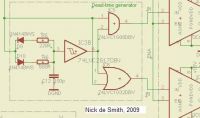
NOTE: The inverting driver (UCC37321) is driven from the OR gate...
Full Bridge
The design is completely modular with both FB & HB versions for both FET & IGBT - easy to swap round for fun. The controller sits on top of this board and has been removed for the photo below.
Here is the prototype full bridge board (FET version) about to be tested...

Full Bridge Schematic
Controller
This can run in SSTC or DRSSTC mode and has built-in thermal management & protection together with optical link, remote control/information panel & dead-time control etc. etc.
Completed controller mounted on FET full bridge:
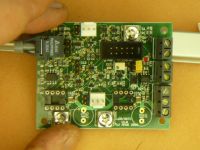
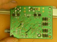
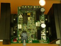
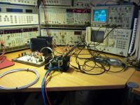
Test harness:
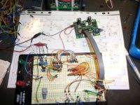
Test rig:
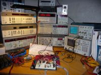
Synchroniser, optical link & feedback working:
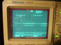
Dead time generation working (needs minor adjustment):
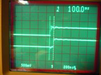
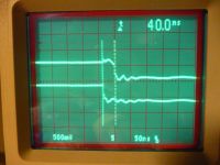
Checking one side of the full bridge gate phasing:
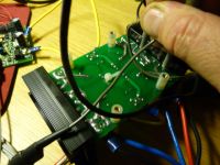
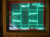
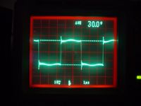
Gate waveforms are in anti-phase and look ok:
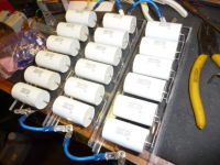
Adjustable MMC (bleed resistors on underside):
New test rig running at 190kHz with fibre optic interrupter:
Primary current measured using Pearson CT 150 - 15V in making 30Vp-p:
http://4hv.org/e107_plugins/forum/forum_viewtopic.php?90019.post
Re: uDR/SSTC design - updated with full bridge testing and current monitoring..
LithiumLord, Thu Jun 25 2009, 04:55PM
heh, kinda alike to what I use, the only difference is the usage of single delay and two different logic types for output. I prefer two separate delays and two AND gates as it utilizes one AND gate IC and some of hc14's gates you are not using completely anyway most likely - so, two ICs vs three ;) Also less parts, as you are no longer forced to use the diodes.
Re: uDR/SSTC design - updated with full bridge testing and current monitoring..
Nicko, Thu Jun 25 2009, 05:18PM
Well, you might save 1 component as you'll have an extra passive (capacitor) but you'll also be using more gates, and you'll note I'm using TinyLogic, which means the footprint is.... well... tiny ! (and no wasted gates).
Nicko, Thu Jun 25 2009, 05:18PM
LithiumLord wrote ...
...so, two ICs vs three ;) Also less parts, as you are no longer forced to use the diodes.
...so, two ICs vs three ;) Also less parts, as you are no longer forced to use the diodes.
Well, you might save 1 component as you'll have an extra passive (capacitor) but you'll also be using more gates, and you'll note I'm using TinyLogic, which means the footprint is.... well... tiny ! (and no wasted gates).
Re: uDR/SSTC design - updated with full bridge testing and current monitoring..
Z28Fistergod, Thu Jun 25 2009, 07:38PM
That looks just like a circuit used to provide independent turn on and turn off waveforms at the gate of an IGBT or MOSFET. Finn hammer uses an almost identical circuit in his design too. If you came up with that on your own then that's good, although it's always a bummer to find out that one of your innovations is old news.
Also you have the problem of the intrinsic delay associated with your circuit. I don't want to sound too critical but schmitt triggers aren't supposed to be used in that way either, a comparator would be ideal.
Re: uDR/SSTC design - updated with full bridge testing and current monitoring..
Nicko, Thu Jun 25 2009, 07:52PM
What I haven't seen used before (not in these parts anyway) is recombining the delayed pulse with the original using just two gates to generate the correct deadtimes. It's so simple...
Nicko, Thu Jun 25 2009, 07:52PM
Z28Fistergod wrote ...
That looks just like a circuit used to provide independent turn on and turn off waveforms at the gate of an IGBT or MOSFET. Finn hammer uses an almost identical circuit in his design too. If you came up with that on your own then that's good, although it's always a bummer to find out that one of your innovations is old news.
I think you've missed the point - The trick with a schmitt input & the two diodes/resistors has probably been around for 20 or 30 years (or more) - it's a standard logic trick and nothing new in that whoever uses it . Just looked at what I think you are referring to (Prediktor?) and whilst Finn uses the same trick as part of his ZCS detection, it's not anything to do with dead time.That looks just like a circuit used to provide independent turn on and turn off waveforms at the gate of an IGBT or MOSFET. Finn hammer uses an almost identical circuit in his design too. If you came up with that on your own then that's good, although it's always a bummer to find out that one of your innovations is old news.
What I haven't seen used before (not in these parts anyway) is recombining the delayed pulse with the original using just two gates to generate the correct deadtimes. It's so simple...
Re: uDR/SSTC design - updated with full bridge testing and current monitoring..
Z28Fistergod, Thu Jun 25 2009, 08:52PM
Well no I didn't miss the point, this will probably sound bad but I didn't see what was so great about the AND gate and the OR gate combination, so I assumed you were talking about the diode resistor capacitor network.
I'd like to see the rest of you schematic because I think you may have overlooked something. It looks like the output of the OR gate will always be greater than 50% duty cycle and the output of the AND gate will always be less than 50% duty cycle. This is probably not good, and you might want to rethink your design.
Re: uDR/SSTC design - updated with full bridge testing and current monitoring..
Nicko, Thu Jun 25 2009, 09:22PM
The design of the output is quite intentional - and, amusingly, quite subtle - The GDT drivers are the "standard" UCC 3732x pair (see original post) - one inverts its enable pin, the other does not - when driven by the pair of signals from the two gates, the dead time is generated -, i.e. one output is positive logic, the other negative which is why you thought that there was an error - it looks "wrong" at first sight, but isn't.
Run a brief simulation in LTspice or similar and you'll see it does actually work, counter-intuitive though it may appear...
HTH
Nicko, Thu Jun 25 2009, 09:22PM
Z28Fistergod wrote ...
Well no I didn't miss the point, this will probably sound bad but I didn't see what was so great about the AND gate and the OR gate combination, so I assumed you were talking about the diode resistor capacitor network.
I'd like to see the rest of you schematic because I think you may have overlooked something. It looks like the output of the OR gate will always be greater than 50% duty cycle and the output of the AND gate will always be less than 50% duty cycle. This is probably not good, and you might want to rethink your design.
The design of the output is quite intentional - and, amusingly, quite subtle - The GDT drivers are the "standard" UCC 3732x pair (see original post) - one inverts its enable pin, the other does not - when driven by the pair of signals from the two gates, the dead time is generated -, i.e. one output is positive logic, the other negative which is why you thought that there was an error - it looks "wrong" at first sight, but isn't.
Run a brief simulation in LTspice or similar and you'll see it does actually work, counter-intuitive though it may appear...
HTH
Re: uDR/SSTC design - updated with full bridge testing and current monitoring..
Z28Fistergod, Thu Jun 25 2009, 09:32PM
Oops, your right. You must have the inverting driver on the OR gate.
Z28Fistergod, Thu Jun 25 2009, 09:32PM
Oops, your right. You must have the inverting driver on the OR gate.
Re: uDR/SSTC design - updated with full bridge testing and current monitoring..
Nicko, Thu Jun 25 2009, 09:43PM
Exactly.
My point really with this very small offering is that simple can be quite cute - as you said, its just a couple of gates and a delay - the trick is combining that with the input to generate the correct drive for the UCCs - the absolute lack of complexity is exactly what makes it so neat (IMHO). Just replace the resistors with multi-turn pots and you have fully adjustable dead time.
When I looked a few months ago at how others were generating dead time, assuming they bothered at all, I was surprised at how complex they'd made it. A bit of thought, playing with LTspice & a breadboard, and a far simpler solution emerges... less often really is more...
Nicko, Thu Jun 25 2009, 09:43PM
Z28Fistergod wrote ...
Oops, your right. You must have the inverting driver on the OR gate.
Oops, your right. You must have the inverting driver on the OR gate.
Exactly.
My point really with this very small offering is that simple can be quite cute - as you said, its just a couple of gates and a delay - the trick is combining that with the input to generate the correct drive for the UCCs - the absolute lack of complexity is exactly what makes it so neat (IMHO). Just replace the resistors with multi-turn pots and you have fully adjustable dead time.
When I looked a few months ago at how others were generating dead time, assuming they bothered at all, I was surprised at how complex they'd made it. A bit of thought, playing with LTspice & a breadboard, and a far simpler solution emerges... less often really is more...
Re: uDR/SSTC design - updated with full bridge testing and current monitoring..
Z28Fistergod, Thu Jun 25 2009, 09:48PM
I agree with less is more most of the time. What drove you to bother with the dead time in the first place?
Z28Fistergod, Thu Jun 25 2009, 09:48PM
I agree with less is more most of the time. What drove you to bother with the dead time in the first place?
Re: uDR/SSTC design - updated with full bridge testing and current monitoring..
Nicko, Thu Jun 25 2009, 09:54PM
Nicko, Thu Jun 25 2009, 09:54PM
Z28Fistergod wrote ...
I agree with less is more most of the time. What drove you to bother with the dead time in the first place?
I intend to use this board for other sorts of drive as well as GDTs - I want to completely eliminate the possibility of shoot through...I agree with less is more most of the time. What drove you to bother with the dead time in the first place?
Re: uDR/SSTC design - updated with full bridge testing and current monitoring..
Terry Fritz, Fri Jun 26 2009, 10:43PM
I like it!!
Dead time circuits always slowed everything down so we avoided them like the plague. But now with Finn's Predikter, dead time is far far more friendly!! Shoot through is very bad and I give it 1mS in a far different application
We really need to take a whole new look at gate drive timing now!
Terry
Terry Fritz, Fri Jun 26 2009, 10:43PM
I like it!!
Dead time circuits always slowed everything down so we avoided them like the plague. But now with Finn's Predikter, dead time is far far more friendly!! Shoot through is very bad and I give it 1mS in a far different application

We really need to take a whole new look at gate drive timing now!
Terry
Re: uDR/SSTC design - updated with full bridge testing and current monitoring..
Z28Fistergod, Sat Jun 27 2009, 01:18AM
I was thinking about your circuit again and the dead time has the potential to be non uniform. Theoretically if the charging resistor was very small and the discharge resistor very large, you could end up with almost a 50% duty cycle out of the non inverting driver, and much less out of the inverting driver. Of course you can adjust this so the duty cycles are uniform with pots. If I were using the circuit I would use a comparator with the threshold set at 1/2 VCC, and a single pot and capacitor. That way the duty cycle of each driver is always equal. My 2 cents.
Re: uDR/SSTC design - updated with full bridge testing and current monitoring..
Nicko, Sat Jun 27 2009, 06:44AM
Nicko, Sat Jun 27 2009, 06:44AM
Z28Fistergod wrote ...
Theoretically if the charging resistor was very small and the discharge resistor very large, you could end up with almost a 50% duty cycle out of the non inverting driver, and much less out of the inverting driver. Of course you can adjust this so the duty cycles are uniform with pots.
Any circuit has the potential to be broken by bad component choice - If you look at the two resistor values I use, you will see that they are asymmetric - the reason for this is explained above - the values chosen result in a perfectly symmetrical output.Theoretically if the charging resistor was very small and the discharge resistor very large, you could end up with almost a 50% duty cycle out of the non inverting driver, and much less out of the inverting driver. Of course you can adjust this so the duty cycles are uniform with pots.
Re: uDR/SSTC design - updated with full bridge testing and current monitoring..
Z28Fistergod, Sat Jun 27 2009, 11:54AM
Sure most circuits won't work right without the correct component values. The difference is that you have two variables to produce one adjustment. It could be a pain to watch the scope and try to detect a 1% difference in the duty cycle between the two drivers.
Re: uDR/SSTC design - updated with full bridge testing and current monitoring..
Nicko, Mon Jul 06 2009, 08:29AM
Updated to include cleaner description & photo of prototype driver board...
Nicko, Mon Jul 06 2009, 08:29AM
Updated to include cleaner description & photo of prototype driver board...
Re: uDR/SSTC design - updated with full bridge testing and current monitoring..
Herr Zapp, Tue Jul 07 2009, 07:16AM
Nicko -
Interesting approach to the dead-time issue ........ have you fired up this driver & bridge combination yet, powering either a dummy load or a real TC?
Not sure I understand your last post ...... is there more information available somewhere (complete driver & bridge schematics, driver board photos, scope shots showing delay timing, etc)?
Regards,
Herr Zapp
Re: uDR/SSTC design - updated with full bridge testing and current monitoring..
Nicko, Tue Jul 07 2009, 10:15AM
I've tested the bridge on a dummy load with a frigged set of drivers, but the real controller board is still being made - its all very small SMD - the total size of the controller is 53mm x 68mm approx - double sided with a few components on the bottom. I don't know why, but I'm drawn to "small & neat" not "big & scary"...
I'll happily put up the schematics when the board is built, probably in two weeks time as I'm buried at work and the board house takes 10 days to do fine-pitched boards. There will undoubtedly be errors which I'd like to fix. I have no time yet to update my web site with this but will do as time permits. I'm driven mainly by the autumn UK Cambridge Teslathon which last year had quite a dramatic conclusion
I have all the simulation stuff in LTspice which looks good - If you want I'll post that - of course, practical realisation is another world, so "first light" may make the whole thing catch fire....
I updated the original post in this thread with a photo of one of the bridge options - the FET FB - not rocket science - I also changed the name of the thread - I've added the schematic to the top post.
Should I start a new project thread or just keep updating this one? Should I update "in-line" or the first post?
Cheers
Nicko, Tue Jul 07 2009, 10:15AM
Herr Zapp wrote ...
Interesting approach to the dead-time issue ........ have you fired up this driver & bridge combination yet, powering either a dummy load or a real TC?
Not sure I understand your last post ...... is there more information available somewhere (complete driver & bridge schematics, driver board photos, scope shots showing delay timing, etc)?
I've tested the bridge on a dummy load with a frigged set of drivers, but the real controller board is still being made - its all very small SMD - the total size of the controller is 53mm x 68mm approx - double sided with a few components on the bottom. I don't know why, but I'm drawn to "small & neat" not "big & scary"...
I'll happily put up the schematics when the board is built, probably in two weeks time as I'm buried at work and the board house takes 10 days to do fine-pitched boards. There will undoubtedly be errors which I'd like to fix. I have no time yet to update my web site with this but will do as time permits. I'm driven mainly by the autumn UK Cambridge Teslathon which last year had quite a dramatic conclusion

I have all the simulation stuff in LTspice which looks good - If you want I'll post that - of course, practical realisation is another world, so "first light" may make the whole thing catch fire....
I updated the original post in this thread with a photo of one of the bridge options - the FET FB - not rocket science - I also changed the name of the thread - I've added the schematic to the top post.
Should I start a new project thread or just keep updating this one? Should I update "in-line" or the first post?
Cheers
Re: uDR/SSTC design - updated with full bridge testing and current monitoring..
Nicko, Tue Jul 07 2009, 10:35AM

With the component values selected in the schematic clip in the top post, you get an approx 80nS shoulder on each crossing.
I will post proper scope shots as soon as I get them...
Nicko, Tue Jul 07 2009, 10:35AM
Herr Zapp wrote ...
... scope shots showing delay timing, etc...?
Here's the LTspice simulation output showing the current through the GDT primary:... scope shots showing delay timing, etc...?

With the component values selected in the schematic clip in the top post, you get an approx 80nS shoulder on each crossing.
I will post proper scope shots as soon as I get them...
Re: uDR/SSTC design - updated with full bridge testing and current monitoring..
Nicko, Tue Jul 14 2009, 09:04PM
New boards finally arrived today. Hopefully start assembly this weekend (under the microscope...). On a course all week, so I'm going to have to wait... It's small, very small...
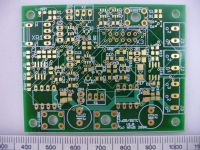
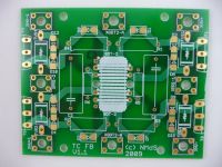
uDR/SSTC Controller board
This is a daughter board for the full bridge board below. When roatated by 90 degrees, it sits across the bridge board about 3cm up.
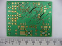
uDR/SSTC Full bridge board (IGBT or FET)
This can be seen assembled in the first post of this thread.
Nicko, Tue Jul 14 2009, 09:04PM
New boards finally arrived today. Hopefully start assembly this weekend (under the microscope...). On a course all week, so I'm going to have to wait... It's small, very small...
uDR/SSTC Controller board
This is a daughter board for the full bridge board below. When roatated by 90 degrees, it sits across the bridge board about 3cm up.


uDR/SSTC Full bridge board (IGBT or FET)
This can be seen assembled in the first post of this thread.

Re: uDR/SSTC design - updated with full bridge testing and current monitoring..
Herr Zapp, Wed Jul 15 2009, 12:04AM
Nicko -
Very nice looking boards.
I assume that you are using a stereoscope during soldering?
In another thread, there is an ongoing discussion on PCB fabrication, on-line fab houses, etc. What design tool did you use, and who fabbed the boards?
Regards,
Herr zapp
Re: uDR/SSTC design - updated with full bridge testing and current monitoring..
Nicko, Fri Jul 24 2009, 11:48AM
Thanks for the feedback - still putting the boards together - last bits should arrive this weekend. I use a good USB microscope for fine detail work - its a b*gger but as I get older, I've had to start using varifocal glasses, and SMD gets harder to do. However, a good binocular uscope is on the list (recommendations welcome). The boards above normally use nothing smaller than 0603 (mostly 0805) and chips no smaller than SOT-23.
Everything is done in Eagle (Pro version) - boards fabbed by Olimex. They did charge me a bit extra for the bridge board as I deliberately left some of the polygons exposed (no silk screen) as I want to silver-solder-load the high current traces. All that gold does look nice though
Synthesis is mostly in LTspice, physical modelling in SolidEdge.
Not sure if I will build it this w/e as feeling rough - half my staff are either down or going down with H1N1. Rats.
Rats.
Nicko, Fri Jul 24 2009, 11:48AM
Herr Zapp wrote ...
Nicko -
Very nice looking boards.
I assume that you are using a stereoscope during soldering?
In another thread, there is an ongoing discussion on PCB fabrication, on-line fab houses, etc. What design tool did you use, and who fabbed the boards?
Nicko -
Very nice looking boards.
I assume that you are using a stereoscope during soldering?
In another thread, there is an ongoing discussion on PCB fabrication, on-line fab houses, etc. What design tool did you use, and who fabbed the boards?
Thanks for the feedback - still putting the boards together - last bits should arrive this weekend. I use a good USB microscope for fine detail work - its a b*gger but as I get older, I've had to start using varifocal glasses, and SMD gets harder to do. However, a good binocular uscope is on the list (recommendations welcome). The boards above normally use nothing smaller than 0603 (mostly 0805) and chips no smaller than SOT-23.
Everything is done in Eagle (Pro version) - boards fabbed by Olimex. They did charge me a bit extra for the bridge board as I deliberately left some of the polygons exposed (no silk screen) as I want to silver-solder-load the high current traces. All that gold does look nice though

Synthesis is mostly in LTspice, physical modelling in SolidEdge.
Not sure if I will build it this w/e as feeling rough - half my staff are either down or going down with H1N1.
 Rats.
Rats.Re: uDR/SSTC design - updated with full bridge testing and current monitoring..
Nicko, Wed Sept 16 2009, 03:27AM
So I've invested in a decent solder paste applicator, an infrared pre-heater & SMD infrared oven.
Hopefully, over the next week or so, I should get the boards built (after some experimentation with some lesser boards)...
Sigh. Why is nothing simple...
Nicko, Wed Sept 16 2009, 03:27AM
Herr Zapp wrote ...
Very nice looking boards.
I assume that you are using a stereoscope during soldering?
In another thread, there is an ongoing discussion on PCB fabrication, on-line fab houses, etc. What design tool did you use, and who fabbed the boards?
Hmmm... there has been a delay in making up these boards as my eyesight was not fully up to it, and even though I use nice Metcal MX500 soldering equipment, that wasn't either.Very nice looking boards.
I assume that you are using a stereoscope during soldering?
In another thread, there is an ongoing discussion on PCB fabrication, on-line fab houses, etc. What design tool did you use, and who fabbed the boards?
So I've invested in a decent solder paste applicator, an infrared pre-heater & SMD infrared oven.
Hopefully, over the next week or so, I should get the boards built (after some experimentation with some lesser boards)...
Sigh. Why is nothing simple...
Re: uDR/SSTC design - updated with full bridge testing and current monitoring..
brtaman, Wed Sept 16 2009, 08:22PM
Wow, looking good, Nicko.
Very nice and clean full-bridge design. Waiting to see it all in action. With all your new electronic goodies, shouldn't be that long. :)
brtaman, Wed Sept 16 2009, 08:22PM
Wow, looking good, Nicko.
Very nice and clean full-bridge design. Waiting to see it all in action. With all your new electronic goodies, shouldn't be that long. :)
Re: uDR/SSTC design - updated with full bridge testing and current monitoring..
Steve Conner, Wed Sept 16 2009, 09:31PM

At work, we have to deal with 0603 and smaller, but we all hate it and would make everything out of DIPs and 1/4 watt resistors if we could still get them. I recently blew up a chip in a 2x2mm QFN with exposed thermal pad, and had to get it off the board and solder on a replacement.
Steve Conner, Wed Sept 16 2009, 09:31PM
Nicko wrote ...
Sigh. Why is nothing simple...
You brought it on yourself by using SMTs! Should have gone for the Duplo sized through-hole stuff Sigh. Why is nothing simple...

At work, we have to deal with 0603 and smaller, but we all hate it and would make everything out of DIPs and 1/4 watt resistors if we could still get them. I recently blew up a chip in a 2x2mm QFN with exposed thermal pad, and had to get it off the board and solder on a replacement.
Re: uDR/SSTC design - updated with full bridge testing and current monitoring..
brtaman, Wed Sept 16 2009, 09:41PM
Haha, nice one. Too true though. :)
brtaman, Wed Sept 16 2009, 09:41PM
Steve McConner wrote ...

Nicko wrote ...
Sigh. Why is nothing simple...
Should have gone for the Duplo sized through-hole stuff Sigh. Why is nothing simple...

Haha, nice one. Too true though. :)
Re: uDR/SSTC design - updated with full bridge testing and current monitoring..
Nicko, Thu Sept 17 2009, 07:38AM
There's lots of folk doing BIG/HUMUNGOUS but not many going in the other direction. I'm a big fan of what Derek and others have done... anyway., BIG scares me...
Initially bought a cheap pneumatic dispenser - bad move bought about by breaking one of my own long standing/cardinal rules - i.e. get the best tools you can afford. Cheap, in this case, meant waste of time and rubbish quality. Time is not something I have a whole lot of, so sent that one back and purchased a much better one. Got some fresh paste with the correct viscosity and profile from Farnell this week - costs three times what it does in the USA...
I'm not sure yet about the infrared oven - its a T-962 (pretty much only type available) - lots of 'em on eBay - mixed reviews on the web from users though, mostly complaining about hot-spots on larger boards... Unit construction looks good, so I'm hopeful for smaller boards like these at least. Will test this weekend...
Basic rule of tools: Cheap, long-lasting, good. Choose any two... (you won't get all three)
Nicko, Thu Sept 17 2009, 07:38AM
Steve McConner wrote ...

True - though I've been pretty much all SMT for years. These boards are almost entirely 0805 / SOT-23 or larger and I never used to have problems with them. Main problem has been paste application - just using a syringe has proved... shall we say, problematic... certainly for a dense board like this...Nicko wrote ...
Sigh. Why is nothing simple...
You brought it on yourself by using SMTs! Should have gone for the Duplo sized through-hole stuff Sigh. Why is nothing simple...

There's lots of folk doing BIG/HUMUNGOUS but not many going in the other direction. I'm a big fan of what Derek and others have done... anyway., BIG scares me...
Initially bought a cheap pneumatic dispenser - bad move bought about by breaking one of my own long standing/cardinal rules - i.e. get the best tools you can afford. Cheap, in this case, meant waste of time and rubbish quality. Time is not something I have a whole lot of, so sent that one back and purchased a much better one. Got some fresh paste with the correct viscosity and profile from Farnell this week - costs three times what it does in the USA...
I'm not sure yet about the infrared oven - its a T-962 (pretty much only type available) - lots of 'em on eBay - mixed reviews on the web from users though, mostly complaining about hot-spots on larger boards... Unit construction looks good, so I'm hopeful for smaller boards like these at least. Will test this weekend...
Basic rule of tools: Cheap, long-lasting, good. Choose any two... (you won't get all three)
Re: uDR/SSTC design - updated with full bridge testing and current monitoring..
Steve Conner, Thu Sept 17 2009, 04:28PM
I've moved this thread to the Projects board at Nicko's request.
Nick, your experience reminds me of an Ao Yue hot-air rework station I had the misfortune to be involved with.
Steve Conner, Thu Sept 17 2009, 04:28PM
I've moved this thread to the Projects board at Nicko's request.
Nick, your experience reminds me of an Ao Yue hot-air rework station I had the misfortune to be involved with.
Re: uDR/SSTC design - updated with full bridge testing and current monitoring..
Nicko, Tue Oct 20 2009, 06:03PM
System Diagram
Assembled controller board (with correct littlelogic SOT-23s)...


Nicko, Tue Oct 20 2009, 06:03PM
System Diagram
Assembled controller board (with correct littlelogic SOT-23s)...


Re: uDR/SSTC design - updated with full bridge testing and current monitoring..
Nicko, Wed Oct 28 2009, 07:44PM
Top post updated with controller board, dead-time & full bridge testing
ONLY TWO DAYS UNTIL CAMBRIDGE!
ARGH!!
Nicko, Wed Oct 28 2009, 07:44PM
Top post updated with controller board, dead-time & full bridge testing
ONLY TWO DAYS UNTIL CAMBRIDGE!
ARGH!!
Re: uDR/SSTC design - updated with full bridge testing and current monitoring..
Coronafix, Thu Oct 29 2009, 09:25AM
It's looking great Nick!! Have you got the primary and secondary made yet? Hope you make it.
Coronafix, Thu Oct 29 2009, 09:25AM
It's looking great Nick!! Have you got the primary and secondary made yet? Hope you make it.
Re: uDR/SSTC design - updated with full bridge testing and current monitoring..
Nicko, Thu Nov 26 2009, 08:44PM
Just come back to this - didn't quite make it work in time for the Cambridge 'thon, but all working now.
Top post in this thread updated with a few new photos at end (MMC, new test rig etc.). Got a Pearson 150 current monitor. Lovely lovely toy! (two more Pearsons (410/411) on their way...
First light next week, I hope...
Re: uDR/SSTC design - updated with full bridge testing and current monitoring..
Dalus, Fri May 28 2010, 07:36PM
Can I ask where you the pearson ct's from? Looking for a proper CT myself.
Dalus, Fri May 28 2010, 07:36PM
Can I ask where you the pearson ct's from? Looking for a proper CT myself.
Re: uDR/SSTC design - updated with full bridge testing and current monitoring..
Nicko, Fri May 28 2010, 09:20PM
They are one of the better investments I've made - I doubt they'll lose any value, and their specifications are just amazing... Fantastic for calibrating bridges & DRSSTCs etc...
Cheers
Nicko, Fri May 28 2010, 09:20PM
Dalus wrote ...
Can I ask where you the pearson ct's from? Looking for a proper CT myself.
They crop up on eBay from time to time - not cheap, but wait a bit and you'll get one at a reasonable price.Can I ask where you the pearson ct's from? Looking for a proper CT myself.
They are one of the better investments I've made - I doubt they'll lose any value, and their specifications are just amazing... Fantastic for calibrating bridges & DRSSTCs etc...
Cheers
Re: uDR/SSTC design - updated with full bridge testing and current monitoring..
Paul Benham, Wed Feb 22 2012, 06:06PM
Hi Nick,
How did you get on with driving a GDT with dead time?
Is it really necessary to have dead time when using a GDT?
I know a lot of people are using deadtime.
Does the output of the GDT have deadtime?
Nicely made boards too.
Cheers,
Paul.
Paul Benham, Wed Feb 22 2012, 06:06PM
Hi Nick,
How did you get on with driving a GDT with dead time?
Is it really necessary to have dead time when using a GDT?
I know a lot of people are using deadtime.
Does the output of the GDT have deadtime?
Nicely made boards too.
Cheers,
Paul.
Print this page