
Another plasma speaker [edit: photo]
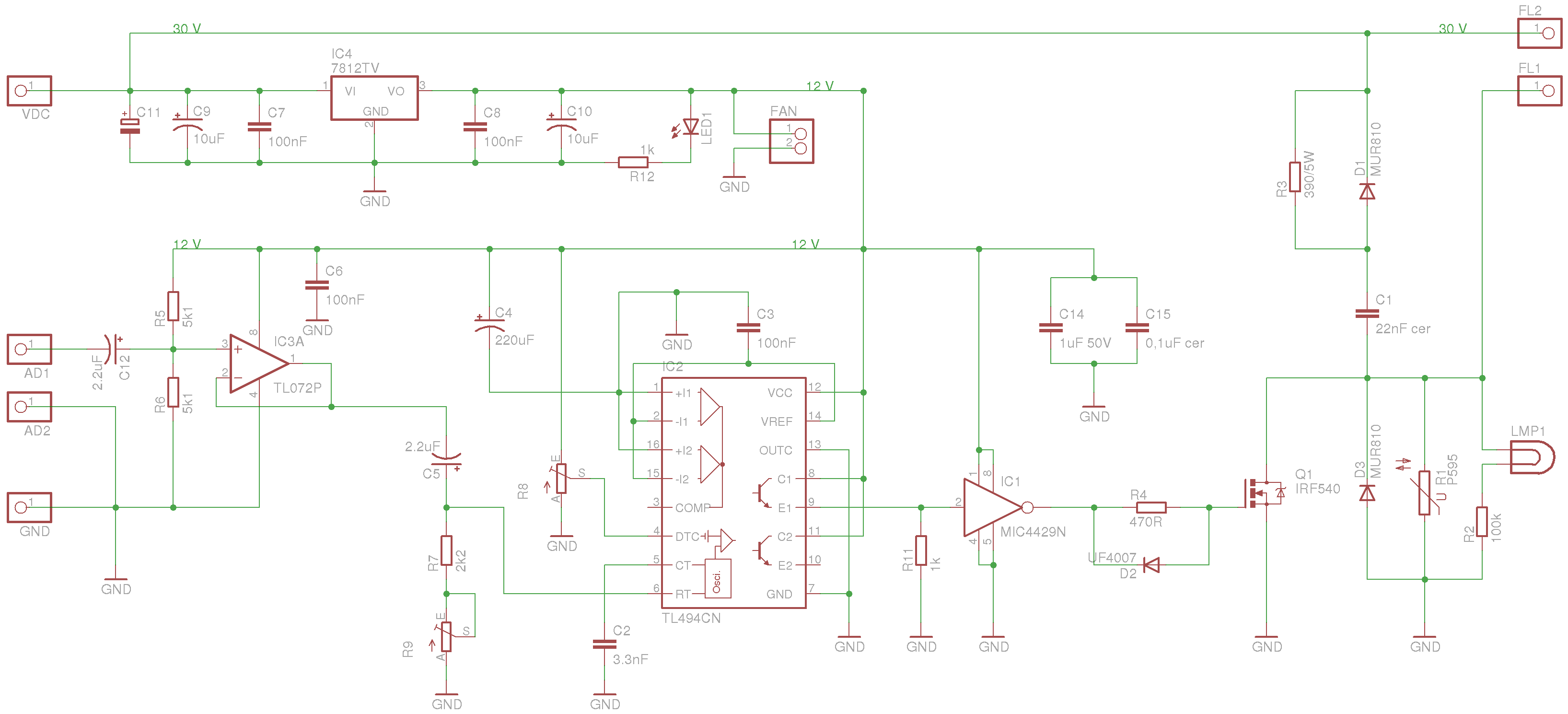
tobias, Thu May 21 2009, 11:52AMInspired by Richard's project a few months ago I decided to build a Plasma Speaker. After a few attempts I did a nice Frequency Modulated circuit with the TL494, a 'voltage follower' opamp for a high impedance audio in and a mic4429 as a mosfet driver:

The sound is amazing besides the low power output.
I'm running it at 30 V @ 2,4 A (see video), 95 kHz base frequency, 12 turns external primary on the flyback.
The main problem I have is the kickback of the flyback when it's turned off. I found on the net a few flyblack snubber circuits and tried everyone. Some did nothing. Others just killed the arc. And one of them (see schematic) seems to work well. But the 390 ohm resistor is getting very hot. Mosfet heating at this power is OK.
Trying to put a 0,22 uF 400 V cap in parallel with the primary seems to make the arc hotter, but did not change the input power nor heating.
Schematic
.
Video
.
Next step is a DIY woodbox for it, and paint it black.
Any help would be appreciated.
Re: Another plasma speaker [edit: photo]
GeordieBoy, Thu May 21 2009, 12:01PM
Snubber design is a complicated subject, so it is hard to advise on individual cases without knowing all of the numbers.
Bare in mind that snubbers generally shift dissipation from silicon to resistors. So, for example, a turn-off snubber that catches what you call the "kickback" from the flyback transformer will prevent avalanching of the MOSFET (reducing it's heating) but will disipate this energy in the clamp circuit resistor instead.
The best type of snubber to use is a lossless (or quasi-resonant) snubber like that used inside the TV set that the flyback was pulled from. This typically uses a capacitor and fast diode across the switch. The basic circuit is shown here:

You have to mess about with the capacitor value, operating frequency and off-time of the gate-drive to get the correct waveforms. Once everything is right, there are virtually no switching losses in the circuit, and the peak flyback voltage is ideally just under the Vmax of the switch.
-Richie,
Re: Another plasma speaker [edit: photo]
tobias, Thu May 21 2009, 12:11PM
Nice Richie!
I will try it!
I have a few MUR820 here. It should make it.
Can you just give me a 'start' value for the cap? I'm running it at 30 V 2,7 A..
And another important question: I did not tried to use the scope at the primary (showing gate on the video). There is a risk to do so?? Can I blow the scope up?
Best regards,
Tobias
Re: Another plasma speaker [edit: photo]
tobias, Sat May 23 2009, 02:57PM
Yesterday I spent 2 hours on the lab messing with capacitor values for the snubber.
I've got the desired waveform with a 0,01 uF 400 V cap, running at 135 kHz, 30 V. With just 0,90 A a nice and smooth arc played crystal sound. The mosfet was unbelievable cold. But the distance between electrodes has to be less than 15 mm to form the arc. Too bad, I want at least 30 mm.
Trying to get the correct waveform with more power I blew up a mosfet and two 0,22 uF 400 V caps that overheated while I was changing frequency (on the 60 to 150 kHz range).
Any suggestions about values to try? Should I have to try bigger or smaller capacitances to get the correct snubber setup for a longer arc?
Re: Another plasma speaker [edit: photo]
GeordieBoy, Sat May 23 2009, 03:42PM
In short the primary of the flyback transformer should be resonant at a frequency that is at least half that who's period is equal to the off-time of the switch. i.e. You must allow sufficient off-time for the primary and snubber cap to undergo a half-cycle of resonant operation before the MOSFET switches on again.
Just play with the cap value, the operating frequency and the duty ratio until you see the right drain voltage waveform. You really do need to be able to see the drain voltage waveform though to do this optimisation. There isn't any other way of getting it right as far as I know. A x10 probe should suffice provided you're not expecting to see more than a few hundred volts there. If you are using a TV HOT for the switch and expect a thousand volts or more, then you will need a x100 HV probe for the scope to measure it safely.
-Richie,
Re: Another plasma speaker [edit: photo]
Dr. Dark Current, Sun May 24 2009, 10:47AM
Remember that if you use this kind of driver, you must make sure the transistor turns on with zero (or near-zero) voltage across it, otherwise it may get damaged. This is impossible with dynamic loads such as arcs. Here's my latest effort of protecting the transistor if it turns on with non-zero volts, with some crude description. Remember that it's just an experimental schematic and component values are given for the supply voltage (55V).
Dr. Dark Current, Sun May 24 2009, 10:47AM
GeordieBoy wrote ...
The best type of snubber to use is a lossless (or quasi-resonant) snubber like that used inside the TV set that the flyback was pulled from. This typically uses a capacitor and fast diode across the switch. The basic circuit is shown here:
The best type of snubber to use is a lossless (or quasi-resonant) snubber like that used inside the TV set that the flyback was pulled from. This typically uses a capacitor and fast diode across the switch. The basic circuit is shown here:
Remember that if you use this kind of driver, you must make sure the transistor turns on with zero (or near-zero) voltage across it, otherwise it may get damaged. This is impossible with dynamic loads such as arcs. Here's my latest effort of protecting the transistor if it turns on with non-zero volts, with some crude description. Remember that it's just an experimental schematic and component values are given for the supply voltage (55V).

Re: Another plasma speaker [edit: photo]
tobias, Sun May 24 2009, 01:52PM
Dr. Kilovolt
May I ask why 21 kHz driving frequency? It's right after the audible range but I think you are not using that for audio modulation, right?
Tomorrow I will go to the lab trying to get both circuits working and see what they do on the scope. I'll bring back some pictures of the waveforms on the scope for the thread.
Re: Another plasma speaker [edit: photo]
Killa-X, Sun May 24 2009, 02:51PM
I think with me, My snubber resulted using 2 capacitors, 1 diode+resistor in parallel, and a varistor accross the + - of the whole thing. My issue is the resistor getting hot evne though its rated 10W but its fine in the heatsink i made. Else it resulted (due to the primary capacitor) in a MUCH thicker arc, and made very loud music :) for a 555, it sounded good :D
Tobias, At least you used a case for your plasma speaker, I forgot
Maybe it's my heatsink, but even with no snubber, just flyback, my mosfet never got warm. I know its rated 500V 20A however, but seriously, it never gets warm. The heatsink is like rated 80W is more I think, as the base is 4mm thick, and it was a 30 dollar sink. Even my 75V doesn't heat that thing, But i'll admit theirs a slight change of my room lights at that power.
Re: Another plasma speaker [edit: photo]
Dr. Dark Current, Sun May 24 2009, 03:30PM
Sorry, that frequency is for efficient transformer driving. Of course you should use more for audio, and accordingly smaller cap. (maybe double the frequency - 4x smaller cap, but I'm not sure about this now)
Dr. Dark Current, Sun May 24 2009, 03:30PM
tobias wrote ...
Dr. Kilovolt
May I ask why 21 kHz driving frequency? It's right after the audible range but I think you are not using that for audio modulation, right?
Tomorrow I will go to the lab trying to get both circuits working and see what they do on the scope. I'll bring back some pictures of the waveforms on the scope for the thread.
Sorry, that frequency is for efficient transformer driving. Of course you should use more for audio, and accordingly smaller cap. (maybe double the frequency - 4x smaller cap, but I'm not sure about this now)
Re: Another plasma speaker [edit: photo]
tobias, Sun May 24 2009, 06:06PM
I'm using ~100 kHz. And your snubber notes says that if I lower the voltage 2x then the cap must be 4x bigger. So I will start trying the range from 0,05 to 0,1 uF. I only have 400 V rated caps but my supply voltage is only 30 V.
I noticed that the arc gets hotter with a parallel cap on the primary without any changes on the power consumption or mosfet heating. But I dont know if that's a good thing because my tungsten electrode gets really hot then.
The tube is painted black now. I want to polish the aluminium and the copper electrode before finishing this project =)

mod edit: oversized pix, site rules say 400 pixels max plz!
tobias, Sun May 24 2009, 06:06PM
Dr. Kilovolt wrote...
Sorry, that frequency is for efficient transformer driving. Of course you should use more for audio, and accordingly smaller cap. (maybe double the frequency - 4x smaller cap, but I'm not sure about this now)
I'm using ~100 kHz. And your snubber notes says that if I lower the voltage 2x then the cap must be 4x bigger. So I will start trying the range from 0,05 to 0,1 uF. I only have 400 V rated caps but my supply voltage is only 30 V.
Killa-X wrote...
I think with me, My snubber resulted using 2 capacitors, 1 diode+resistor in parallel, and a varistor accross the + - of the whole thing. My issue is the resistor getting hot evne though its rated 10W but its fine in the heatsink i made. Else it resulted (due to the primary capacitor) in a MUCH thicker arc, and made very loud music :) for a 555, it sounded good :D
Tobias, At least you used a case for your plasma speaker, I forgot
I noticed that the arc gets hotter with a parallel cap on the primary without any changes on the power consumption or mosfet heating. But I dont know if that's a good thing because my tungsten electrode gets really hot then.
The tube is painted black now. I want to polish the aluminium and the copper electrode before finishing this project =)
mod edit: oversized pix, site rules say 400 pixels max plz!
Re: Another plasma speaker [edit: photo]
tobias, Mon May 25 2009, 05:22PM
News from the Lab!
I spent 3h on the lab today trying to get the snubber working (the design that Richie proposed).
First of all I choosed a fixed frequency to work: 95 kHz
Then I start with a 0,01 uF 400 V cap and adjusted the dead time to get the right gate waveform (or tried to).
If the cap value was not good I changed for a larger one..
My best shot was a 220 nF cap, that gave me the following waveform:

After a few minutes running the FET was cold. The arc holds steady with a higher distance between electrodes. The power comsumption was the same as before. The only concern was the cap heating too much, but nothing exploded =)
Then I discovered a HUGE problem: when I tried to get some music of it I discovered that the sound was weak and distorced.
Is that snubber a good design to Audio Modulated plasma speaker?
Is that waveform good enought? I think I can make it better but before killing more caps, did anyone tried that snubber with audio before? Without audio the results are good!
My second try was Dr. Kilovolt design. But I have no idea how to make a 1 uH air core coil. =P
Can someone help me with a short description of how to make one?
tobias, Mon May 25 2009, 05:22PM
News from the Lab!
I spent 3h on the lab today trying to get the snubber working (the design that Richie proposed).
First of all I choosed a fixed frequency to work: 95 kHz
Then I start with a 0,01 uF 400 V cap and adjusted the dead time to get the right gate waveform (or tried to).
If the cap value was not good I changed for a larger one..
My best shot was a 220 nF cap, that gave me the following waveform:
After a few minutes running the FET was cold. The arc holds steady with a higher distance between electrodes. The power comsumption was the same as before. The only concern was the cap heating too much, but nothing exploded =)
Then I discovered a HUGE problem: when I tried to get some music of it I discovered that the sound was weak and distorced.
Is that snubber a good design to Audio Modulated plasma speaker?
Is that waveform good enought? I think I can make it better but before killing more caps, did anyone tried that snubber with audio before? Without audio the results are good!
My second try was Dr. Kilovolt design. But I have no idea how to make a 1 uH air core coil. =P
Can someone help me with a short description of how to make one?
Re: Another plasma speaker [edit: photo]
Killa-X, Mon May 25 2009, 07:14PM
I'm not sure what snubber design you used...I just remember when I ran my snubber backwards, I had thicker arcs. The right way was thin and long. But when I had it backwards, The music was very loud due to the thicker arcs. A bit too loud for me personally, However, I'm sure yours sounds better. I had a 555 with audio on pin 5, it sounded like grate quality but I'm sure a real audio amp would be better
Print this page