
"Thumper"
Finn Hammer, Fri May 01 2009, 08:05PMAs you all know, good old Dr. Spark gave me a Ward DRSSTC driver board, of the 2005 edition. I have populated it, and it is now driving a nice little 40n60 bridge.
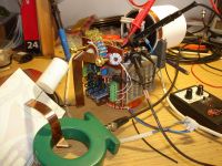
With a 1.5µF cap and associated inductance, it is resonating at 32kHz. I look at it as my breadbord where I am going to test out features that I think might be good to have in a DRSSTC driver board.
Starting out with something that already has proven it´s worth seems like the best approach.
Big bricks have delays close to a microsecond, so it would seem like a good idea to initiate the switching of the bridge well in advance of the tank current's zero crossing. I am indebted to Richie Burnett for the method I use to predict this crossing:
Using a 0.01V/A current transformer (50turns, 0.5ohms burden) adding a bit of inductance in series with the burden, the voltage of the combo is made to lead the tank current. A small 10turn coil, 3/4 of an inch in diameter is enough to extract a signal that is 2µS ahead of the current:
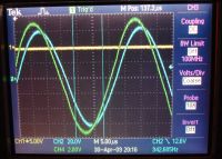
This signal is fed into pin 2 of a 311 comparator, and the output looks like this:
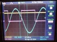
You will see, that I now have a perfectly good clock signal that leads the current by a couple µS.
This generously advanced signal forms the basis of the final clock:
Passing it trough 2 schmitt inverters, interspaced with a suitable RC time delay, the final clock signal can be made to move from "well ahead" of CZC:
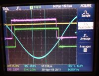
To much too late. Not that this last timing is of interest other than to show that it is possible:
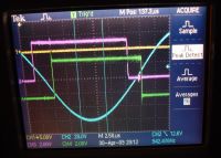
So far so good, but does it work?, is it possible to make the bridge switch with this clock, instead if the original, "brute force" diode clamped signal.
Absolutely! And this small video shows how it is possible to advance and retard the clock relative to CZC, and how this effects the voltage spikes produced by the bridge.
Notice that I am unable to achieve perfect switching on both edges simultaneously. I assume that adding a deadtime generating circuit will take care of that. I think this will come in handy, when I start to work with the big bricks.
So far so good, enjoy the video:

Cheers, Finn Hammer
Re: "Thumper"
Dr. Drone, Sat May 02 2009, 04:23AM

Dr. Drone, Sat May 02 2009, 04:23AM

Re: "Thumper"
Finn Hammer, Sat May 02 2009, 06:01PM
ROFL, you are funny indeed!.
But no confirmed mods before making sparks all day.
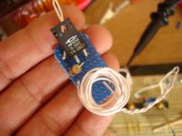
This mod is not going to break anybody's budget. Here is the burden board, showing the 0.5 ohms non-inductive resistor, and the nifty inductor which advances the trace for current zero crossing predict.
The small 10ohm resistor on end, is across the inductor, to damp out oscillations which I am not sure are real or measurement error. Don't do any harm, though.
There is one strange thing I don´t understand:
The 311 has an open collector output, and when the signal is taken from the collector, the responce is 4 times faster then whan the signal is taken from the emitter. (Assuming same input signal slope)
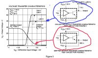
It is real enough, I can see it on the scope.
Anybody able to explain this strange behaviour? After all, it is the response of the same device. Only thing I can think of, is that we are seing the current being pumped into the base-emitter region, and so the difference of the curves shows this current, and thus also the turn on delay of this output transistor.
Anybody?
Cheers, Finn Hammer
Finn Hammer, Sat May 02 2009, 06:01PM
Dr. Spark wrote ...
You just cannot leave it alone…….your such a pain in the butt; however, would love to hire you in R/D dept……..and keep you in the back so do not scare/alarm the customers! Hee hee
Going to finalize the new Driver Board (naming it H3W_2009 rev 0) , so hurry up and get me all modifications proven…..! Just kidding, no hurry as still stuffing the last of the old boards and one is for Quadzilla Pulser?
Cheers,
Ch
BTW Nice Skull Indeed!
ROFL, you are funny indeed!.
But no confirmed mods before making sparks all day.
This mod is not going to break anybody's budget. Here is the burden board, showing the 0.5 ohms non-inductive resistor, and the nifty inductor which advances the trace for current zero crossing predict.
The small 10ohm resistor on end, is across the inductor, to damp out oscillations which I am not sure are real or measurement error. Don't do any harm, though.

There is one strange thing I don´t understand:
The 311 has an open collector output, and when the signal is taken from the collector, the responce is 4 times faster then whan the signal is taken from the emitter. (Assuming same input signal slope)

It is real enough, I can see it on the scope.
Anybody able to explain this strange behaviour? After all, it is the response of the same device. Only thing I can think of, is that we are seing the current being pumped into the base-emitter region, and so the difference of the curves shows this current, and thus also the turn on delay of this output transistor.
Anybody?
Cheers, Finn Hammer
Re: "Thumper"
Steve Ward, Sat May 02 2009, 06:49PM
Finn, the common collector (or emitter follower) has lower inherent gain because of the negative feedback implied by the rising emitter voltage, so it slows itself down.
Ummm... could you PLEASE get a decent comparator for this?
The issue i always had with this type of circuit (phase lead) is that i figured it always had some limit on dynamic range. But, i suppose there are comparators out there that will take a pretty big signal swing and still work fine with 10's of mV level stuff.
The other issue i worry about is that you could accidentally over compensate and start switching too early, which is a lot nastier than switching late.
The un-even switching times bother me too, i suspect it has to do with your delay circuit.
Anyway, i look forward to your results for a fully implemented system... surely it cant be *this* easy .
.
Steve Ward, Sat May 02 2009, 06:49PM
Finn, the common collector (or emitter follower) has lower inherent gain because of the negative feedback implied by the rising emitter voltage, so it slows itself down.
Ummm... could you PLEASE get a decent comparator for this?
The issue i always had with this type of circuit (phase lead) is that i figured it always had some limit on dynamic range. But, i suppose there are comparators out there that will take a pretty big signal swing and still work fine with 10's of mV level stuff.
The other issue i worry about is that you could accidentally over compensate and start switching too early, which is a lot nastier than switching late.
The un-even switching times bother me too, i suspect it has to do with your delay circuit.
Anyway, i look forward to your results for a fully implemented system... surely it cant be *this* easy
 .
.Re: "Thumper"
Steve Conner, Sat May 02 2009, 07:59PM
I'd be worried about the little air cored coil picking up magnetic field from something that it shouldn't.
Steve Conner, Sat May 02 2009, 07:59PM
I'd be worried about the little air cored coil picking up magnetic field from something that it shouldn't.
Re: "Thumper"
Finn Hammer, Sat May 02 2009, 08:43PM
I can't claim to know what makes a comparator decent. I just grabbed 311 because I have them, they take + - 15V and seem fast enough. I don't really want something that is so fast it rips the surroundings apart . And the open collectod output made interface to 5V logic easy.
Do you have one in mind you would like to suggest ?

I am going to use this circuit which has the advantage that I can adjust both transitions separately: This will take care of clock 50/50 duty cycle. (Disregard component values)

You are probably right . After all the name of the game is "sparks all day"
That´s the acid test.
Cheers, Finn Hammer
Finn Hammer, Sat May 02 2009, 08:43PM
Steve Ward wrote ...
Ummm... could you PLEASE get a decent comparator for this?
Ummm... could you PLEASE get a decent comparator for this?
I can't claim to know what makes a comparator decent. I just grabbed 311 because I have them, they take + - 15V and seem fast enough. I don't really want something that is so fast it rips the surroundings apart
 . And the open collectod output made interface to 5V logic easy.
Do you have one in mind you would like to suggest ?
Steve Ward wrote ...
The issue i always had with this type of circuit (phase lead) is that i figured it always had some limit on dynamic range. But, i suppose there are comparators out there that will take a pretty big signal swing and still work fine with 10's of mV level stuff.
I am pretty surprised that it kicks in at only 5V into the bridge, and still syncs well.The issue i always had with this type of circuit (phase lead) is that i figured it always had some limit on dynamic range. But, i suppose there are comparators out there that will take a pretty big signal swing and still work fine with 10's of mV level stuff.
Steve Ward wrote ...
The other issue i worry about is that you could accidentally over compensate and start switching too early, which is a lot nastier than switching late.
I guess only an experiment can answer that.The other issue i worry about is that you could accidentally over compensate and start switching too early, which is a lot nastier than switching late.
Steve Ward wrote ...
The un-even switching times bother me too, i suspect it has to do with your delay circuit.
Absolutely. And the unequal turn on and turn off delays of the 311.The un-even switching times bother me too, i suspect it has to do with your delay circuit.
I am going to use this circuit which has the advantage that I can adjust both transitions separately: This will take care of clock 50/50 duty cycle. (Disregard component values)

Steve Ward wrote ...
Anyway, i look forward to your results for a fully implemented system... surely it cant be *this* easy .
.
Anyway, i look forward to your results for a fully implemented system... surely it cant be *this* easy
 .
.You are probably right
 . After all the name of the game is "sparks all day"
That´s the acid test.
Cheers, Finn Hammer
Re: "Thumper"
Steve Ward, Sat May 02 2009, 09:59PM
I was just thinking you should use a faster comparator, the LT1016 comes to mind. But, perhaps i remembered incorrectly because i thought the 311 had a delay in the uS range, not the 130nS range, so maybe its not that big of a deal, but the less compensation required, the better, id think.
Stable oscillation at only 5V input is good, thats about what my systems normally require to get going at all, and maybe arent even fully stable until about 20-30VDC on the bridge. Of course, the sensitivity could be improved for lower voltage/current systems so its all relative i guess.
Re: "Thumper"
Finn Hammer, Sun May 03 2009, 11:35AM
Maby this is the time to pull out that sheet of µMetal to solder a nice guarding sheath.
Btw. I fitted the delay network where I can shift each transition independently and recorded another video, where I show the improvement in voltage overshoot/oscillations possible by fitting the current prediction circuit.

It does exactly what I have always wanted in a controller: give me an opportunity to act. To remove transition overshoot/ringing, with my diddle-stick, instead of having to mess around with gate resistor diode networks.
Gate resistors are 20ohms, to calm things down, btw.
I spent a lot of time figuring out why the comparator went into oscillations at times. It appears that inbetween bursts, both inputs are at same potential, or close.
What would be a good solution to this?
I could introduce a few, say 5mV, hysteresis, but how to do that in a comparator with + - supply?
I just realize that I don't understand the function of the balance pin.
I could need a basic text on comparators, if any of you can help me with that, I*d appreciate it a lot.
Cheers, Finn Hammer
Finn Hammer, Sun May 03 2009, 11:35AM
Steve McConner wrote ...
I'd be worried about the little air cored coil picking up magnetic field from something that it shouldn't.
I'd be worried about the little air cored coil picking up magnetic field from something that it shouldn't.
Maby this is the time to pull out that sheet of µMetal to solder a nice guarding sheath.
Btw. I fitted the delay network where I can shift each transition independently and recorded another video, where I show the improvement in voltage overshoot/oscillations possible by fitting the current prediction circuit.

It does exactly what I have always wanted in a controller: give me an opportunity to act. To remove transition overshoot/ringing, with my diddle-stick, instead of having to mess around with gate resistor diode networks.
Gate resistors are 20ohms, to calm things down, btw.
I spent a lot of time figuring out why the comparator went into oscillations at times. It appears that inbetween bursts, both inputs are at same potential, or close.
What would be a good solution to this?
I could introduce a few, say 5mV, hysteresis, but how to do that in a comparator with + - supply?
I just realize that I don't understand the function of the balance pin.
I could need a basic text on comparators, if any of you can help me with that, I*d appreciate it a lot.
Cheers, Finn Hammer
Re: "Thumper"
Bennem, Sun May 03 2009, 12:09PM
Hi Finn,
Great work!
How are you adjusting your prediction circuit to eliminate the spikes?
is it the 'differance signal between the original drive signal to the the predicted signal'?
Have you got a diagram to help understand it better?
Mel
Bennem, Sun May 03 2009, 12:09PM
Hi Finn,
Great work!
How are you adjusting your prediction circuit to eliminate the spikes?
is it the 'differance signal between the original drive signal to the the predicted signal'?
Have you got a diagram to help understand it better?
Mel
Re: "Thumper"
Finn Hammer, Sun May 03 2009, 03:56PM
Thanks, Bennem.
Here it is:

1K on bal to B+ solved oscillation on input, gues it shifts the reference of one pin a bit.
If you want to try yourself, run the coil as it is, and monitor pin4 on 74HC109 on Wards troller, to assure it matches output of zero predicter.
When you have same signals, connect predicter to pin 4 and disconnect pin 12 on 74HC14 to allow swing on flipflop.
Enjoy!
Cheers, Finn Hammer
Finn Hammer, Sun May 03 2009, 03:56PM
Thanks, Bennem.
Here it is:

1K on bal to B+ solved oscillation on input, gues it shifts the reference of one pin a bit.
If you want to try yourself, run the coil as it is, and monitor pin4 on 74HC109 on Wards troller, to assure it matches output of zero predicter.
When you have same signals, connect predicter to pin 4 and disconnect pin 12 on 74HC14 to allow swing on flipflop.
Enjoy!
Cheers, Finn Hammer
Re: "Thumper"
Bennem, Sun May 03 2009, 06:37PM
Hi Finn,
Thanks for the info,
Do you think you could get the same results with a high Freq Res coil?
I'm going to try it with my small 300Khz coil as i have one of Steve's
older version circuits in that coil.
Mel
Bennem, Sun May 03 2009, 06:37PM
Hi Finn,
Thanks for the info,
Do you think you could get the same results with a high Freq Res coil?
I'm going to try it with my small 300Khz coil as i have one of Steve's
older version circuits in that coil.
Mel
Re: "Thumper"
Finn Hammer, Sun May 03 2009, 07:43PM
For the low frequency coils the reason is the long shut off delays of the bricks, mainly.
But in a high frequency coil, the delays are smaller, but so is the frequency, so the delay to period ratio might be comparable.
All I can say, give it a try. Worst case scenario: the thing stops to switch, no big deal, just rewire and make sparks all day!
I am pondering a new version.
First of all, there was the problem with oscillation due to equal input voltages. I can solve it by referring the one side of the burden a few millivolts away from - input, the other to + input. Better it by adding a bit of hysteresis.
This can not be done with an open collector output, so I have chosen a totem pole output comparator, AD790 which has some good features. Built in hysteresis, 500µV, will accept up to +- 18V supply, fast, but not too fast, 40nS etc.
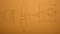
Bias the - input for adjustable offset. And maby looking a bit more nice in a way. Have to wait for the comparator, though.
EDIT:
Woops. Having read up on the datasheet of AD790: It has a 5Vlogic output totem pole. What a wonderfull comparator!, that means I can forget about the interfacing transistor. This is looking good indeed.
Cheers, Finn Hammer
Finn Hammer, Sun May 03 2009, 07:43PM
Bennem wrote ...
Hi Finn,
Thanks for the info,
Do you think you could get the same results with a high Freq Res coil?
I'm going to try it with my small 300Khz coil as i have one of Steve's
older version circuits in that coil.
Mel
It certainly is not designed for that. But I can't see why not, for different reasons, though.Hi Finn,
Thanks for the info,
Do you think you could get the same results with a high Freq Res coil?
I'm going to try it with my small 300Khz coil as i have one of Steve's
older version circuits in that coil.
Mel
For the low frequency coils the reason is the long shut off delays of the bricks, mainly.
But in a high frequency coil, the delays are smaller, but so is the frequency, so the delay to period ratio might be comparable.
All I can say, give it a try. Worst case scenario: the thing stops to switch, no big deal, just rewire and make sparks all day!
I am pondering a new version.
First of all, there was the problem with oscillation due to equal input voltages. I can solve it by referring the one side of the burden a few millivolts away from - input, the other to + input. Better it by adding a bit of hysteresis.
This can not be done with an open collector output, so I have chosen a totem pole output comparator, AD790 which has some good features. Built in hysteresis, 500µV, will accept up to +- 18V supply, fast, but not too fast, 40nS etc.

Bias the - input for adjustable offset. And maby looking a bit more nice in a way. Have to wait for the comparator, though.
EDIT:
Woops. Having read up on the datasheet of AD790: It has a 5Vlogic output totem pole. What a wonderfull comparator!, that means I can forget about the interfacing transistor. This is looking good indeed.
Cheers, Finn Hammer
Re: "Thumper"
Bennem, Mon May 04 2009, 08:04AM
Cool.....I look forward to seeing your results!!
Bennem, Mon May 04 2009, 08:04AM
Cool.....I look forward to seeing your results!!
Re: "Thumper"
GeordieBoy, Tue May 05 2009, 11:36AM
Hi Finn,
Great work. You can actually vary the amount of phase-lead in the feedback signal from the CT just by making the inductive part of the burden impedance variable. i.e. Use a tiny adjustable pot-core or I.F. transformer type coil that has an adjustable ferrite slug. You should then be able to adjust the inductive part of the burden impedance to get the amount of phase-lead that you want.
Steve W is right about the dangers of too much phase-lead in the feedback path. Present DRSSTC's with no phase-lead compensation switch a load current that has leading power factor. To put this another way, the load current has already passed through zero and changed polarity before the message gets through the controller and tells the IGBTs to actually switch over. Funnily enough, this is the way it should be for IGBTs....
If you add too much phase-lead into the feedback path at the operating frequency you will end up with the IGBTs switching in advance of the load current passing through zero. This is generally bad for slow IGBTs as they have stored charge which will then be swept out in the form of current tailing. The further the IGBT switches ahead of the current zero, the higher the instantaneous current will be at turn-off and the greater the tail-current losses will be.
So in short it is always better to let the IGBT's collector current fall smoothly to zero, THEN turn off the IGBT when there can be no current tailing. Then, only when the first IGBT has been allowed sufficient time to turn-off, the opposing IGBT can be turned on.
The holy-grail of timing that you should be aiming for is this:
1. Turn off the current carrying IGBT as soon as possible after its collector current has fallen to zero and the load current has started to build in it's co-packaged free-wheel diode. (The device can be turned off with a very rapid slope because current has already commutated to the co-pack diode some time ago!)
2. Wait sufficient time for this IGBT to regain blocking ability before trying to turn on the opposing IGBT.
3. Turn on the opposing IGBT with a controlled slope so that the rising load current is now commutated from the other device's free-wheel diode to this IGBT in a smooth and controlled manner.
If all of these things are performed as quickly as possible after the current zero-crossing then the load current should not have had time to rise very much from its zero crossing. Therefore turn-on losses should not be very high, despite the controlled turn-on slope. Note that the controlled turn-on slope may actually reduce turn-on losses in the IGBTs due to forced reverse recovery in the opposing device's co-pack free-wheel diodes. Again, it is advisable to start the turn-on process as early as possible. The longer the load current is allowed to flow in the free-wheel diode the higher the current magnitude will rise, and the worse the reverse-recovery spike will be when the diode turns off.
The phase-lead network I told you about with the L+R burden impedance is great for compensating for inherent delays in the control and gate-drive paths. However, you should be careful not to introduce overall net phase-lead for the reasons stated above. It is also important to realise that the amount of time-lead in nanoseconds is dependent on the amplitude of the current signal being sensed. That is to say that the output of the comparator will switch further ahead of the current zeroes if the current being sensed is large, than if the current being sensed is small. The L part of the burden impedance basically adds a "differential" component to the otherwise proportional output from the CT. So the output is no longer proportional to the sinewave load current being sensed, but is instead proportional to the sinewave load current plus a certain amount of the differential of this sinewave load current. The more rapid the slew of the load current, the earlier the comparator will switch and the more "time-lead" is introduced.
I hope this helps explain the details of how an IGBT inverter operates with a series resonant load. Have fun experimenting.
-Richie,
Re: "Thumper"
Dr. Drone, Tue May 05 2009, 04:37PM

Dr. Drone, Tue May 05 2009, 04:37PM

Re: "Thumper"
Finn Hammer, Tue May 05 2009, 07:32PM
Richie,
I don't plan to shut any device off before current zero crossing (CZC)
But when the turn off delay is the longest of the switching parameters, up in the µS region, That´s why I thought it was prudent to initiate the turn off before CZC.
I read your advice about allowing the IGBT to recompose itself before opening the other one, and this is where the adjustable deadtime circuit comes in. Supported by generous gate resistance, to slow down the turn on. (I don't so easily forget the hardship this reverse recovery current caused us in the CCPS thread.
I had not thought about the effect of increasing current, creating a larger advance in timing, and this means that the design has to be optimised for the end of the burst. Maby the deadtime window can be long enough to accomodate the differences here.
Chris, I also read your objections, and you obviously have a point. Fatboy is hard to beat, and why mess with a proven design.
The 1968 Shelby Mustang GT500 KR was a very successfull design in it's time.

But it didn't stop further development effort, and the well deserved success of the Ward controller should not do so either.
Your many years in a craftmans environment must surely also have taught you another thing: Apprentices ask around with the masters that care to share insight, then they go and do what they want themselves.
But we take every bit of detail you said that can go into this new design, be it bypassing, tuning or basic circuit ideas.
I bet you did the same back in your rookie years.
And like I stated early in this thread, hell I can always go back to the basic controller as it is.
I got the AD790 comparator, and it works really well, the internal hysteresis, 500µV did the trick, but biassing the negative input a couple millivolts is probably going to be needed.
The offset here has to be greater than any voltage induced in the burden coil, and this can only be determined in a running coil. I*l look into guarding the coil, and of course orienting it perpendicular to the main source of mutual induction: the primary coil.
I also got a bit of work done on the over current detector.
Here I am also going another route, but not much:
I always felt that it was not too much to ask, that it was a straightforward procedure to set the maximum current trip point. This is a place where I don't want to experiment, but rather would demand a well defined voltage point to set the trip current.
I do so by using a precision rectifier instead if a diode bridge,
I know, Chris, you are going to puke now, but really, it is just one op amp more instead of the diode bridge.
This rectifier rectifies a current transformers output, and the result is fed into a comparator, as already, only this way, the trip voltage is well defined. Like incorporating a measurement instrument in the controller.
I do read your warning about RF, the enemy. I will fight it by your own measures: Decoupling and layout.
No power pin on any device is going to be more than 3mm away from it's decoupling cap, there are going to be analogue ground planes separated from digital ground plane, decoupling and bypassing galore!
Allow me to scite a great piece of inspiration I read the other day: (it is prolly a classic already)
"The breadboard is both the designer's playground and proving ground. It is here that Reality resides, and paper (and computer designs) meet their ruler. More than anything else, breadboarding is an iterative procedure, an odd amalgam of experience guiding an innocent, ignorant, explorative spirit. A key is to be willing to try things out, sometimes for not very good reasons. Invent problems and solutions, guess carefully and wildly, throw rocks and see what comes loose. Invent and design experiments, and follow them wherever they lead".
Jim Williams wrote AN72 in 1998, and subtitled it:
Guidance to put civilised speed to work.
With that guidance, and that of yourself: honorouble list members and friends, I intend to persue this idea to success, or to it's pitifull failiure.
Cheers, Finn Hammer
Finn Hammer, Tue May 05 2009, 07:32PM
Richie,
I don't plan to shut any device off before current zero crossing (CZC)
But when the turn off delay is the longest of the switching parameters, up in the µS region, That´s why I thought it was prudent to initiate the turn off before CZC.
I read your advice about allowing the IGBT to recompose itself before opening the other one, and this is where the adjustable deadtime circuit comes in. Supported by generous gate resistance, to slow down the turn on. (I don't so easily forget the hardship this reverse recovery current caused us in the CCPS thread.
I had not thought about the effect of increasing current, creating a larger advance in timing, and this means that the design has to be optimised for the end of the burst. Maby the deadtime window can be long enough to accomodate the differences here.
Chris, I also read your objections, and you obviously have a point. Fatboy is hard to beat, and why mess with a proven design.
The 1968 Shelby Mustang GT500 KR was a very successfull design in it's time.

But it didn't stop further development effort, and the well deserved success of the Ward controller should not do so either.
Your many years in a craftmans environment must surely also have taught you another thing: Apprentices ask around with the masters that care to share insight, then they go and do what they want themselves.
But we take every bit of detail you said that can go into this new design, be it bypassing, tuning or basic circuit ideas.
I bet you did the same back in your rookie years.
And like I stated early in this thread, hell I can always go back to the basic controller as it is.
I got the AD790 comparator, and it works really well, the internal hysteresis, 500µV did the trick, but biassing the negative input a couple millivolts is probably going to be needed.
The offset here has to be greater than any voltage induced in the burden coil, and this can only be determined in a running coil. I*l look into guarding the coil, and of course orienting it perpendicular to the main source of mutual induction: the primary coil.
I also got a bit of work done on the over current detector.
Here I am also going another route, but not much:
I always felt that it was not too much to ask, that it was a straightforward procedure to set the maximum current trip point. This is a place where I don't want to experiment, but rather would demand a well defined voltage point to set the trip current.
I do so by using a precision rectifier instead if a diode bridge,
I know, Chris, you are going to puke now, but really, it is just one op amp more instead of the diode bridge.
This rectifier rectifies a current transformers output, and the result is fed into a comparator, as already, only this way, the trip voltage is well defined. Like incorporating a measurement instrument in the controller.
I do read your warning about RF, the enemy. I will fight it by your own measures: Decoupling and layout.
No power pin on any device is going to be more than 3mm away from it's decoupling cap, there are going to be analogue ground planes separated from digital ground plane, decoupling and bypassing galore!
Allow me to scite a great piece of inspiration I read the other day: (it is prolly a classic already)
"The breadboard is both the designer's playground and proving ground. It is here that Reality resides, and paper (and computer designs) meet their ruler. More than anything else, breadboarding is an iterative procedure, an odd amalgam of experience guiding an innocent, ignorant, explorative spirit. A key is to be willing to try things out, sometimes for not very good reasons. Invent problems and solutions, guess carefully and wildly, throw rocks and see what comes loose. Invent and design experiments, and follow them wherever they lead".
Jim Williams wrote AN72 in 1998, and subtitled it:
Guidance to put civilised speed to work.
With that guidance, and that of yourself: honorouble list members and friends, I intend to persue this idea to success, or to it's pitifull failiure.
Cheers, Finn Hammer
Re: "Thumper"
Dr. Drone, Tue May 05 2009, 09:22PM

Dr. Drone, Tue May 05 2009, 09:22PM

Re: "Thumper"
Dr. Drone, Tue May 05 2009, 09:26PM

Dr. Drone, Tue May 05 2009, 09:26PM

Re: "Thumper"
GeordieBoy, Tue May 05 2009, 09:45PM
Hi Finn,
All of what you are doing sounds good to me.
Advancing the drive signal to compensate for delays in the control and gate-drive electronics sounds like a sensible approach. As for how much this will increase efficiency, I am not sure for a pulsed application like a DRSSTC. I can say with some certainty that it won't noticeably increase the spark length because efficiency will likely already be in the 90's of percent, but it may reduce the device heating considerably and also reduce reverse recovery problems.
Regarding the phase-lead's dependancy on current amplitude: I would optimise the circuit so that it switches with best performance when current is maximum. This is the normal situation when designing a resonant switched mode power supply. Maximise efficiency at full-power because this is when it matters most. Poor efficiency at low power doesn't imply as much dissipation so is generally not a problem.
Regarding the concerns about interference pickup of that little air-cored coil: I would replace it with a pot-core or IF transformer type with a semi-enclosed bobbin and adjustable core. This will be less susceptible to strong magnetic fields. It may also be wise to orientate it's axis orthogonally to the TC's primary and secondary axes to minimise any remaining coupling.
-Richie,
Re: "Thumper"
Steve Conner, Wed May 06 2009, 10:11AM
Hi all
Having an advance that changes with current may be a good thing, since the turn-off delays of IGBTs probably increase with current too.
My last word on the DRSSTC driver debate was the Mk2 PLL driver that I built.
Steve Conner, Wed May 06 2009, 10:11AM
Hi all
Having an advance that changes with current may be a good thing, since the turn-off delays of IGBTs probably increase with current too.
My last word on the DRSSTC driver debate was the Mk2 PLL driver that I built.
Re: "Thumper"
Finn Hammer, Sun May 10 2009, 05:31PM
All,
Project mooving forward, of course slower than wanted and predicted.
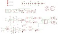
However, here is schematic of controller, only missing status led's:
Burden resistors are mounted on the terminals, so that they can be exchanged together with the current transformer.
And board layout:
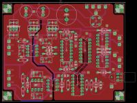
This has been a satisfying job. In the course of drawing the schematic, I finally got the hang of using the supply symbols, which greatly simplifies the schematic.
The layout has separate grounds for analog and digital section, and 100nF bypass capacitors are surface mount cheramics on the back of the board.
Since I etch this board myself, and don´t have trough plating facilities, certain ground connections are pulled over to a via to connect to gnd.
Cheers, Finn Hammer
Finn Hammer, Sun May 10 2009, 05:31PM
All,
Project mooving forward, of course slower than wanted and predicted.
However, here is schematic of controller, only missing status led's:
Burden resistors are mounted on the terminals, so that they can be exchanged together with the current transformer.

And board layout:

This has been a satisfying job. In the course of drawing the schematic, I finally got the hang of using the supply symbols, which greatly simplifies the schematic.
The layout has separate grounds for analog and digital section, and 100nF bypass capacitors are surface mount cheramics on the back of the board.
Since I etch this board myself, and don´t have trough plating facilities, certain ground connections are pulled over to a via to connect to gnd.
Cheers, Finn Hammer
Re: "Thumper"
Finn Hammer, Thu May 14 2009, 09:31PM
Arrh! The joy of prototyping!
Knowing that to make the circuit work, a board has to be laid out, and produced. Early attention to chip power supply has to be taken care of.
To make a 40nS comparator spit perfect square waves, supply decoupling must be done as by the book!
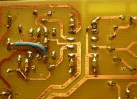
I am the first to regret the shabby look of the etch, but (many good excuses...)It's the small surface mount 0.1µF caps I want to show off, and of course the blue wire shouting GOOF out loud. But never mind, even those many Bourns trimpots are not cheap, it is for sure: another board has to come after this one:
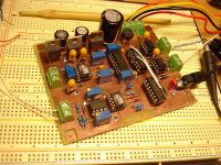
So many hours used to find out: does the idea work?
All the signals check out. I did the gate drivers for 5V since they are going to drive optocouplers ultimately, but since I have already cut traces, I am going to rewire them for 15V and drive the gate transformer for the "dummy"-bridge.
I made some invalid assumptions on the interface from the overcurrent protector too, that have to be worked out.
I have vacation now, and it is agreed that I don't work on the project for a couple days, untill then, I can smile at the memory of that precision rectifyer doing it´s task at 8Vin, and 31kHz:
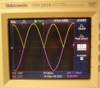
Cheers, Finn Hammer
Finn Hammer, Thu May 14 2009, 09:31PM
Arrh! The joy of prototyping!
Knowing that to make the circuit work, a board has to be laid out, and produced. Early attention to chip power supply has to be taken care of.
To make a 40nS comparator spit perfect square waves, supply decoupling must be done as by the book!

I am the first to regret the shabby look of the etch, but (many good excuses...)It's the small surface mount 0.1µF caps I want to show off, and of course the blue wire shouting GOOF out loud. But never mind, even those many Bourns trimpots are not cheap, it is for sure: another board has to come after this one:

So many hours used to find out: does the idea work?
All the signals check out. I did the gate drivers for 5V since they are going to drive optocouplers ultimately, but since I have already cut traces, I am going to rewire them for 15V and drive the gate transformer for the "dummy"-bridge.
I made some invalid assumptions on the interface from the overcurrent protector too, that have to be worked out.
I have vacation now, and it is agreed that I don't work on the project for a couple days, untill then, I can smile at the memory of that precision rectifyer doing it´s task at 8Vin, and 31kHz:

Cheers, Finn Hammer
Re: "Thumper"
Dr. Drone, Sat May 16 2009, 02:41AM

Dr. Drone, Sat May 16 2009, 02:41AM

Re: "Thumper"
hvguy, Mon May 18 2009, 08:52AM
Great job with this thread, Finn!
I built this exact circuit, LM311 and all (fast comps too), about three years ago. I spent more than a month working with it. I too had good results on the bench and was able to easily adjust the system for perfect switching... BUT it ultimately proved of little use as the change in delay for from ~20ApK to 800Apk in my final test system was just too great and resulted in a phase change much greater than was needed. I tried many different R/L values and different CT ratios, etc. but could not find an ideal situation. This circuit definitely works great with a fixed or lightly varied current source, but with the dynamic load of a DRSSTC it just didn't cut it. It did work well in an SSTC feedback loop though... Ultimately I could not justify using it as the efficiency/performance gains where just not there. Also, since a very high speed comp was necessary to achieve perfect switching it was HIGHLY susceptible to any noise. I always had to run a full AL enclosure with feedthru caps and fiber controls when the system was under full power (~1kw). It was like trying to build a GHz RF amp
That being said, I'm not trying to burst the bubble on this one and I hope you come up with something I missed as this would be a really helpful addition to the classic DRSSTC.
It's funny, I remember around Y2K when I started experimenting with feedback based SSTC's (I believe I was the first or second (Jan Wagner?) to incorporate a feedback loop into a TC system) I accidentally created this situation. It was so bad, in fact, that it lead to me giving up on the CT idea and sticking with voltage feedback (oops!). It was actually Richie who helped me with my first open-loop SSTC so I'm glad to see he's involved with this thread... Good luck!
Oh, BTW, props on the scope; I love my 2014, can't beat the CF card storage and it never skips a beat even when inundated with Kw's of RF.
hvguy, Mon May 18 2009, 08:52AM
Great job with this thread, Finn!
I built this exact circuit, LM311 and all (fast comps too), about three years ago. I spent more than a month working with it. I too had good results on the bench and was able to easily adjust the system for perfect switching... BUT it ultimately proved of little use as the change in delay for from ~20ApK to 800Apk in my final test system was just too great and resulted in a phase change much greater than was needed. I tried many different R/L values and different CT ratios, etc. but could not find an ideal situation. This circuit definitely works great with a fixed or lightly varied current source, but with the dynamic load of a DRSSTC it just didn't cut it. It did work well in an SSTC feedback loop though... Ultimately I could not justify using it as the efficiency/performance gains where just not there. Also, since a very high speed comp was necessary to achieve perfect switching it was HIGHLY susceptible to any noise. I always had to run a full AL enclosure with feedthru caps and fiber controls when the system was under full power (~1kw). It was like trying to build a GHz RF amp

That being said, I'm not trying to burst the bubble on this one and I hope you come up with something I missed as this would be a really helpful addition to the classic DRSSTC.
It's funny, I remember around Y2K when I started experimenting with feedback based SSTC's (I believe I was the first or second (Jan Wagner?) to incorporate a feedback loop into a TC system) I accidentally created this situation. It was so bad, in fact, that it lead to me giving up on the CT idea and sticking with voltage feedback (oops!). It was actually Richie who helped me with my first open-loop SSTC so I'm glad to see he's involved with this thread... Good luck!
Oh, BTW, props on the scope; I love my 2014, can't beat the CF card storage and it never skips a beat even when inundated with Kw's of RF.
Re: "Thumper"
Finn Hammer, Mon May 18 2009, 09:08AM
Thanks, Aron
Your post sure ads to the excitement, but then, WTH, I actually started this idea based on a sample and hold circuit, which will not have any variation in delay due to different output from an inductor.
May have to pull that circuit into service in the end.
Cheers, Finn Hammer
Re: "Thumper"
Finn Hammer, Tue May 19 2009, 08:47PM
All,
Back from Paris, first on the list was to find out, whether the circuit works, (it does so, thank you) and whether the inductive component of the feedback current transformer burden, causes the feedwack signal to advance with rising current.
This does not appear to be the case:
Look at the video linked below:
Green is voltage out of bridge,
Cyan os current in tank, measured with Pearson model 101, and
Magenta is feedback signal, as measured across burden inductor and resistor.
I vary the current in the bridge from 50A to 500A
The 2 Magenta cursor lines help to convince you, that there is hardly any advance in the feedback signal within a 1:10 variation of current.

So now that this taken care of, I'l design a real kiss gate driver centered around the IXDD414 chip, which, since it is delivering it's drive through a 5.6ohm resistor, has more than enough omph:
Swinging up from -10V to +20V the current won't exeed 6A, but the IXDD can source and sink 14A.
Cheers, Finn Hammer
Finn Hammer, Tue May 19 2009, 08:47PM
All,
Back from Paris, first on the list was to find out, whether the circuit works, (it does so, thank you) and whether the inductive component of the feedback current transformer burden, causes the feedwack signal to advance with rising current.
This does not appear to be the case:
Look at the video linked below:
Green is voltage out of bridge,
Cyan os current in tank, measured with Pearson model 101, and
Magenta is feedback signal, as measured across burden inductor and resistor.
I vary the current in the bridge from 50A to 500A
The 2 Magenta cursor lines help to convince you, that there is hardly any advance in the feedback signal within a 1:10 variation of current.

So now that this taken care of, I'l design a real kiss gate driver centered around the IXDD414 chip, which, since it is delivering it's drive through a 5.6ohm resistor, has more than enough omph:
Swinging up from -10V to +20V the current won't exeed 6A, but the IXDD can source and sink 14A.
Cheers, Finn Hammer
Re: "Thumper"
Finn Hammer, Sat May 23 2009, 07:28PM
All,
I admit to being a sucker for symmetry. So the gate driver for "Thumper" had to be designed with this in mind. I fried the 4 IXDD414 chips in short order, no good reason found, so the search for another gate driver started.
I want an optocoupler so that the gates get pulled all the way to -10V, even though there is deadtime. A gate transformer won´t do that.
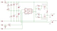
The fast opto's I mentioned earlier demanded a low supply, 6V, and so I deemed them unsuitable for this project. I had a stick with 50 pcs. HCPL3120, and they look perfect for the job. The supply voltage is as high as 30V so it can straddle the gate driver supply, and swing the gates of the PNP - NPN totem pole output from rail to rail. Only thing to find was MOSfets with a 30V Gss rating. A prolonged datasheet search unearthed suitable candidates from Fairchild, both 30V gate voltage and around 15A current rating. FQP17P10 and FQP18N20
I am slowing the turn on of the NPN part, and slowing the turn off of the top PNP part with resistor/diode combinations, to avoid shootthrough.
The optocoupler needs 10mA to light the diode, but I am driving 110mA trough the supply cable, and shunting the 100mA. This way I divide the noise by 10, I hope?.
The propagation delay is 500nS, and this should not be a problem, after all, the current zero prediction scheme was developed with this kind of delays in mind. I may have to measure and select matched pairs for diagonal bricks.
It is the CM600 I intend to drive, but I have 1200A/1700V types in stock too =:-o
The schematic is here:
Getting more and more used to surface mount parts, the board layout looks like this:
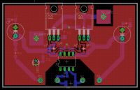
I will etch a prototype tomorrow, and determine the values of the gate resistor/diode networks, even though this has to be done on IRF540/9530 since the fancy good ones from Fairchild are in the mail.
Comments, advice and even flames are welcome!
Cheers, Finn Hammer
Finn Hammer, Sat May 23 2009, 07:28PM
All,
I admit to being a sucker for symmetry. So the gate driver for "Thumper" had to be designed with this in mind. I fried the 4 IXDD414 chips in short order, no good reason found, so the search for another gate driver started.
I want an optocoupler so that the gates get pulled all the way to -10V, even though there is deadtime. A gate transformer won´t do that.
The fast opto's I mentioned earlier demanded a low supply, 6V, and so I deemed them unsuitable for this project. I had a stick with 50 pcs. HCPL3120, and they look perfect for the job. The supply voltage is as high as 30V so it can straddle the gate driver supply, and swing the gates of the PNP - NPN totem pole output from rail to rail. Only thing to find was MOSfets with a 30V Gss rating. A prolonged datasheet search unearthed suitable candidates from Fairchild, both 30V gate voltage and around 15A current rating. FQP17P10 and FQP18N20
I am slowing the turn on of the NPN part, and slowing the turn off of the top PNP part with resistor/diode combinations, to avoid shootthrough.
The optocoupler needs 10mA to light the diode, but I am driving 110mA trough the supply cable, and shunting the 100mA. This way I divide the noise by 10, I hope?.
The propagation delay is 500nS, and this should not be a problem, after all, the current zero prediction scheme was developed with this kind of delays in mind. I may have to measure and select matched pairs for diagonal bricks.
It is the CM600 I intend to drive, but I have 1200A/1700V types in stock too =:-o
The schematic is here:

Getting more and more used to surface mount parts, the board layout looks like this:

I will etch a prototype tomorrow, and determine the values of the gate resistor/diode networks, even though this has to be done on IRF540/9530 since the fancy good ones from Fairchild are in the mail.
Comments, advice and even flames are welcome!
Cheers, Finn Hammer
Re: "Thumper"
Finn Hammer, Mon May 25 2009, 08:08PM
Today, I have been looking at the gate driver, in particular why it is a good idea to keep cross conduction to a minimum in the totem pole output MosFets of the driver.
If you heep the schematic of last post in mind, I will show some scope shots of the cross conduction currents that happen unless the turn on and off of the output transistors are duly subdued.
In this case, I have chosen to mount 470 ohms gate resistors, and 1n5819 diodes, to tame the fet's.
This has caused the Cross Conduction to drop to:
On the falling edge of the gate signal:
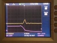
A nice and calm one ampere for 50nS
If I short out the gate resistor, R6 in above schematic, this happens:
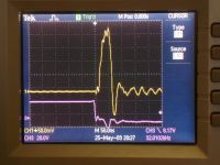
Cross conduction rises to 5 amps, and more important, ugly ringing is introduced.
Same thing on the rising edge, with 470 ohms in place:
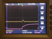
And with R3 shorted:
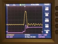
It is the ringing that causes me the most concern.
Look at this rather benign gate voltage/current profile, with the resistors in place:
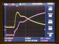
Then relish what the same situation looks like, if shoot trough in the gate driver exists:
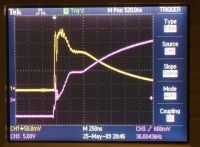
This concludes my take on gate drivers: Keep them nice and clean, before attaching an IGBT.
Cheeers, Finn Hammer
One thing that bothers me: I cannot for the love of god yank more than 4 ampere into those gates, even though the gate resistor is 5 ohms. Go figure......
Finn Hammer, Mon May 25 2009, 08:08PM
Today, I have been looking at the gate driver, in particular why it is a good idea to keep cross conduction to a minimum in the totem pole output MosFets of the driver.
If you heep the schematic of last post in mind, I will show some scope shots of the cross conduction currents that happen unless the turn on and off of the output transistors are duly subdued.
In this case, I have chosen to mount 470 ohms gate resistors, and 1n5819 diodes, to tame the fet's.
This has caused the Cross Conduction to drop to:
On the falling edge of the gate signal:

A nice and calm one ampere for 50nS
If I short out the gate resistor, R6 in above schematic, this happens:

Cross conduction rises to 5 amps, and more important, ugly ringing is introduced.
Same thing on the rising edge, with 470 ohms in place:

And with R3 shorted:

It is the ringing that causes me the most concern.
Look at this rather benign gate voltage/current profile, with the resistors in place:

Then relish what the same situation looks like, if shoot trough in the gate driver exists:

This concludes my take on gate drivers: Keep them nice and clean, before attaching an IGBT.
Cheeers, Finn Hammer
One thing that bothers me: I cannot for the love of god yank more than 4 ampere into those gates, even though the gate resistor is 5 ohms. Go figure......
Re: "Thumper"
hvguy, Tue May 26 2009, 12:37AM
That video looked very promising, Finn. What was the current sweep range (dI)?
I'm glad to see people working with different GD arrangements. It seems everyone was stuck on GDICs for the beginning years of SS work. I too have had unexpected, costly, and seemingly unexplainable failures with GDICs. I stopped using them in most designs. I found the IXYS parts, while quite possibly the best available, where much more susceptible to failure if their rail voltage was higher than their signal input voltage, even though the DS says that should be fine. Their ENA pin also seems very likely to cause a failure if it is noisy.
I am a big believer in GDTs though; you just can't beat galvanic isolation and 0 insertion delay. I usually drive them with either a full bridge of N-CH FETs driven by a tiny GDT and SOGDIC, or a half bridge of P/N-CH parts. Everything is ultra compact SMT, as close to the IGBT as possible.
I'm really looking forward to seeing this system make arcs. Thanks for a good thread...
Re: "Thumper"
Finn Hammer, Tue May 26 2009, 06:00AM
The video showed a current sweep from 50A to 500A.
About gate drive: I am having a very hard time justifying my initial desicion to use opto's and separate gate drivers, when it would be so much simpler to build a nice little semi-high voltage bridge, and drive a step down gate drive transformer.
It is no easy task to configure the totem pole output stage of the driver and get both zero shoot trough as well as high current output ability:
When I slow down the turn on enough to keep shoot trough low, the turn on is prolonged so that the ability to deliver current within the time frame of turning on of the IGBT is impaired.
I will try the old trick with zeners on the gate, which you may recall from the days of the beefy driver.
(didn'd help)
What I _really_ need is a tiny NTC resistor, which could delay the ramp up to miller plateau, then turn low resistance there, to allow fast full turn on.
Well, this is fun anyway, and perhaps I should just make that bridge/gate tranny and get on with it.
Thanks for -your- work. It was the work of pioneers like yourself that got me started.
Cheers, Finn Hammer
Finn Hammer, Tue May 26 2009, 06:00AM
hvguy wrote ...
That video looked very promising, Finn. What was the current sweep range (dI)?
snip
I'm really looking forward to seeing this system make arcs. Thanks for a good thread...
That video looked very promising, Finn. What was the current sweep range (dI)?
snip
I'm really looking forward to seeing this system make arcs. Thanks for a good thread...
The video showed a current sweep from 50A to 500A.
About gate drive: I am having a very hard time justifying my initial desicion to use opto's and separate gate drivers, when it would be so much simpler to build a nice little semi-high voltage bridge, and drive a step down gate drive transformer.
It is no easy task to configure the totem pole output stage of the driver and get both zero shoot trough as well as high current output ability:
When I slow down the turn on enough to keep shoot trough low, the turn on is prolonged so that the ability to deliver current within the time frame of turning on of the IGBT is impaired.
I will try the old trick with zeners on the gate, which you may recall from the days of the beefy driver.
(didn'd help)
What I _really_ need is a tiny NTC resistor, which could delay the ramp up to miller plateau, then turn low resistance there, to allow fast full turn on.
Well, this is fun anyway, and perhaps I should just make that bridge/gate tranny and get on with it.
Thanks for -your- work. It was the work of pioneers like yourself that got me started.
Cheers, Finn Hammer
Re: "Thumper"
Finn Hammer, Tue May 26 2009, 10:11PM
I am obsessed with finding a way to tweak out shoot trough in a pnp/npn totem pole.
The popular explanation is, that shoot trough exists for the range of voltage, where both fet´s are turned on, which in a 30V systen can be as much as 24 volts, from 3V to 27V.
I had so focussed on the linear voltage aspect, that I forgot about the ever so important _time_, and this is why it didn't help to just stick in a zener in series with the gate.
The point is, that it takes *time* for the opto to rise from 0 to 30 volts, in this case 100nS. and then it takes another small 100nS for the upper fet to shut off. Let´s give it another 100nS to settle in.
Then we have a need to, on a positive going edge, to delay the turn on of the low fet with 300nS, to insure that it does not start to conduct before the upper one has shut off.
Below is a schematic that I drew in a frenzy this morning to work, and pondered all day: will it work?
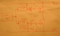
The point here is to spend 300nS filling up the capacitor to zener voltage, before charging the gate.
For 300nS, I would need 10nF and 30 ohms with a 18Volt zener, I ended up with 50 ohms.
Look at this small video, where I sweep the 2 resistors from 0 to 50 ohms, and watch the shoottrough drop from 6A to 100mA
Yellow trace shows the current spikes, green shows one of the fet gates, the other one omitted for clarity.

Looks a bit complicated, but set in smd parts, it should not take much space up on the board, really.
This design has only been tested on protoboard, and I assume it will be better on a proper pcb, which will follow in short order.
Instead of the zener, it would be really cool to use a Sidac, or Trisil, which would break down to 0Volts instead of clamp to zener voltage, in that case, the charge stored in capacitor would become instantly available as gate charge.
I am not shure, however, whether these devices are able to recompose between cycles at 30kHz.
So what, better leave good enough be for now.
Cheers, Finn Hammer
Finn Hammer, Tue May 26 2009, 10:11PM
I am obsessed with finding a way to tweak out shoot trough in a pnp/npn totem pole.
The popular explanation is, that shoot trough exists for the range of voltage, where both fet´s are turned on, which in a 30V systen can be as much as 24 volts, from 3V to 27V.
I had so focussed on the linear voltage aspect, that I forgot about the ever so important _time_, and this is why it didn't help to just stick in a zener in series with the gate.
The point is, that it takes *time* for the opto to rise from 0 to 30 volts, in this case 100nS. and then it takes another small 100nS for the upper fet to shut off. Let´s give it another 100nS to settle in.
Then we have a need to, on a positive going edge, to delay the turn on of the low fet with 300nS, to insure that it does not start to conduct before the upper one has shut off.
Below is a schematic that I drew in a frenzy this morning to work, and pondered all day: will it work?

The point here is to spend 300nS filling up the capacitor to zener voltage, before charging the gate.
For 300nS, I would need 10nF and 30 ohms with a 18Volt zener, I ended up with 50 ohms.
Look at this small video, where I sweep the 2 resistors from 0 to 50 ohms, and watch the shoottrough drop from 6A to 100mA

Yellow trace shows the current spikes, green shows one of the fet gates, the other one omitted for clarity.

Looks a bit complicated, but set in smd parts, it should not take much space up on the board, really.
This design has only been tested on protoboard, and I assume it will be better on a proper pcb, which will follow in short order.
Instead of the zener, it would be really cool to use a Sidac, or Trisil, which would break down to 0Volts instead of clamp to zener voltage, in that case, the charge stored in capacitor would become instantly available as gate charge.
I am not shure, however, whether these devices are able to recompose between cycles at 30kHz.
So what, better leave good enough be for now.
Cheers, Finn Hammer
Re: "Thumper"
Firefox, Tue May 26 2009, 10:46PM
Brilliant use of the RC time constant, Finn. :) Out of curiousity, do you know why you still have 100mA of shoot through, and is this acceptable for a bridge like this?
Firefox, Tue May 26 2009, 10:46PM
Brilliant use of the RC time constant, Finn. :) Out of curiousity, do you know why you still have 100mA of shoot through, and is this acceptable for a bridge like this?
Re: "Thumper"
Finn Hammer, Wed May 27 2009, 04:51AM
Sean,
I am not sure there is any shoottrough left, actually. But the scope shows a bit of riffraff @100mA amplitude, and this could be diode reverse recovery, ground noise on a circuit with non-ideal grounding: no ground plane, or something else that I am unable to account for.
However, the good news is, that the bridge now delivers 10A into the Cm600 gate, with absolute smoothness, and it is this special smoothness that I am going for.
I cannot at the moment see why it does not deliver more, but looking into that.
There are a lot of RC time constants in this thread.
Cheers, Finn Hammer
Finn Hammer, Wed May 27 2009, 04:51AM
Firefox wrote ...
Brilliant use of the RC time constant, Finn. :) Out of curiousity, do you know why you still have 100mA of shoot through, and is this acceptable for a bridge like this?
Brilliant use of the RC time constant, Finn. :) Out of curiousity, do you know why you still have 100mA of shoot through, and is this acceptable for a bridge like this?
Sean,
I am not sure there is any shoottrough left, actually. But the scope shows a bit of riffraff @100mA amplitude, and this could be diode reverse recovery, ground noise on a circuit with non-ideal grounding: no ground plane, or something else that I am unable to account for.
However, the good news is, that the bridge now delivers 10A into the Cm600 gate, with absolute smoothness, and it is this special smoothness that I am going for.
I cannot at the moment see why it does not deliver more, but looking into that.
There are a lot of RC time constants in this thread.
Cheers, Finn Hammer
Re: "Thumper"
Steve Conner, Wed May 27 2009, 09:35AM
Hi Finn,
You were asking why it doesn't deliver more than 10 amps. The current could be limited by stray inductance, because inductance sets up a back EMF against changing current.
It could also be limited by gate capacitance: a capacitance can only draw current equal to C*dv/dt, so maybe you don't have enough dv/dt, if you slowed things down too much in your quest for special smoothness.
Another consideration is that since the gate is a capacitance, and the wiring to it is an inductance, you have a LC circuit. Even with the beefiest gate driver in the universe, with an infinite slew rate and infinite current capacity, the current you can deliver is limited by the surge impedance (sqrt(L/C)) of this circuit. However, if this was the limiting factor you would have a large voltage overshoot, up to 2x.
Re: "Thumper"
GeordieBoy, Wed May 27 2009, 11:15AM
I agree with everything Steve said here. It pretty much sums up gate drive. I smile when I hear of people wanting to buy the latest gate-drive chip that can source more amps to MOSFET gates, and then they tell me they're going to use a Gate Drive Transformer in between. The leakage inductance of the GDT is enough to ensure that the drivier chip never gets anywhere near it's peak current sourcing or sinking ability. And to add insult to injury you usually have to introduce additional gate-damping resistance anyway to tame overshoot and ringing. This resistance further decreases the peak current in practical operation!
On the holy-grail quest to eliminate shoot-through it is worth considering that there are several things that can *appear* like shoot-through. Depending on how you actually examine the bridge circuit to check for shoot-through you can observe any of the following:
1. Shoot-through current down the bridge legs due to cross-conduction of the device channels. This is plain and simple overlap of the conduction periods of the two switching devices and is very bad! If you close one switch before the other one is opened, then the supply is shorted and lots of current will flow during that time.
2. Current surges down the bridge legs due to forced reverse recovery of each device's co-packaged free-wheel diode. Under certain circumstances each free-wheel diode will undergo a forced reverse-recovery event when the opposite switch turns on. This causes a current surge down the bridge leg that looks like shoot-through, and has all of the same detrimental effects. It just happens that the current path is through one switch and one diode instead of through two switches.
3. Current surges down the bridge leg to charge device output capacitances. This is most noticeable in high-frequency high-voltage bridge circuits. Under certain loading conditions the turning on of each switch causes a surge of current to suddenly charge the output capacitance of the opposite device to the supply rail voltage. Again this looks like conventional shoot-through and has the same detrimental effects. This time the current path is through one switch and one switch's device capacitance even though it is "open" or in its "blocking" state!
In a practical system shoot-through current can be comprised of one or two of the above components. Number 1 should be insignificant if the gate-drive signals do not overlap and sufficient deadtime is included to allow each device to fully turn off before the opposing device turns on. The behaviours described in number 2 and number 3 depend on the load presented to the bridge. The capacitive turn-on shoot-through described in number 3 is particularly noticeable when there is no load connected to a bridge being run at high-frequency and high voltage, or when the load appears capacitive. An indutive load and sufficient deadtime can ensure that devices turn on with zero voltage across them and there is no capacitive charging current spikes at turn-on.
Similiarly the behaviour described in number 2 above, is most noticeable with a heavy capacitive load where the load current leads the applied voltage. This causes forced reverse recovery of the free-wheel diodes with the accompanying current spike that sets everything in the circuit ringing! This is most likely the largest cause of losses in a DRSSTC where the switching transistions take place after the load current has changed direction, and where all reasonable precautions have been taken to eliminate simple cross-conduction.
-Richie,
Re: "Thumper"
Dr. Drone, Wed May 27 2009, 05:38PM

Dr. Drone, Wed May 27 2009, 05:38PM

Re: "Thumper"
GeordieBoy, Wed May 27 2009, 06:15PM
I'm guessing that maybe Finn is trying to switch that 4000 amp current in a more controlled way so that he doesn't generate 600 volt spikes across his IGBTs.
Without having to allow +100% voltage margin for switching spikes, he might then choose to increase the supply voltage to process more power and generate bigger sparks.
-Richie,
Re: "Thumper"
Finn Hammer, Wed May 27 2009, 07:38PM
Steve, Richie
I think I can say with certainty that what is seen is "real shoot trough". Both devices are turned on, in a time and voltage range that corresponds with the current spike measured.
It also disappears when the counter measure is implemented.
I have been running it in Microsim today, and this has given me insight that I did not have before.
The voltage available on the gate of the output fet's is related to the zener voltage in a way I had not figured out.
This voltage starts to rise when the zener voltage is reached, and then follows the voltage across the capacitor in the R/C delay line, but offset by the zener voltage.
If I chose a zener voltage up close to Vcc, the charging curve has flattened out considerably, and therefore the gate voltage will rise slowly. This will lead to a slow turn on/off of the output fet, and then also low dv/dt, as Steve mentioned. This is the situation I think is seen now.
To acheive maximum output risetime, the zener voltage has to be chosen at the point where the slope of the R/C network is steepest. For the matematically inclined, this is probably easy to do, but I did it graphically:
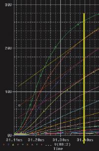
It looks like this happens around 2/3 up, or around 20V.
Let me point out that I think 10A into the gate is about ideal: My reference of excellence is Fatboy, which with a 5.6ohm gate resistor presumably has a gate charging current of 6-8amps.
So when this gate driver does it _without_ gate resistor, and in a way where it swoshes past the miller plateou without hesitation, and without overshoot, much has been acheived.
Time will tell.
Cheers, Finn Hammer
Finn Hammer, Wed May 27 2009, 07:38PM
Steve, Richie
I think I can say with certainty that what is seen is "real shoot trough". Both devices are turned on, in a time and voltage range that corresponds with the current spike measured.
It also disappears when the counter measure is implemented.
I have been running it in Microsim today, and this has given me insight that I did not have before.
The voltage available on the gate of the output fet's is related to the zener voltage in a way I had not figured out.
This voltage starts to rise when the zener voltage is reached, and then follows the voltage across the capacitor in the R/C delay line, but offset by the zener voltage.
If I chose a zener voltage up close to Vcc, the charging curve has flattened out considerably, and therefore the gate voltage will rise slowly. This will lead to a slow turn on/off of the output fet, and then also low dv/dt, as Steve mentioned. This is the situation I think is seen now.
To acheive maximum output risetime, the zener voltage has to be chosen at the point where the slope of the R/C network is steepest. For the matematically inclined, this is probably easy to do, but I did it graphically:

It looks like this happens around 2/3 up, or around 20V.
Let me point out that I think 10A into the gate is about ideal: My reference of excellence is Fatboy, which with a 5.6ohm gate resistor presumably has a gate charging current of 6-8amps.
So when this gate driver does it _without_ gate resistor, and in a way where it swoshes past the miller plateou without hesitation, and without overshoot, much has been acheived.
Time will tell.
Cheers, Finn Hammer
Re: "Thumper"
Dr. Drone, Wed May 27 2009, 09:22PM

Dr. Drone, Wed May 27 2009, 09:22PM

Re: "Thumper"
GeordieBoy, Thu May 28 2009, 11:23AM
I totally agree that allowing a voltage safety margin and running the devices under their voltage rating is a good idea for reliability. Perhaps a similar approach should be adopted for peak current rating of IGBTs in DRSSTCs too!
My overall opinion on this from many years in the power electronics industry is that the IGBT bricks people use for DRSSTCs simply weren't designed to switch thousands of amps at frequencies up to 100kHz. They were designed to switch a few hundred amps at little more than 20kHz because there's little motivation to go any higher in the drives industry. That is why the voltage spikes exist, because the devices were simply never designed for the kind of service that we put them to.
For these reasons I think that investigating any clever drive schemes or snubbers that help improve this situation is commendable. You have to use what you've got, be creative and push the boundaries.
It is possible to run devices very close to their ratings in SSTC applications, you just have to make sure you do everything right. It just happens to be easier to derate everything and consider what's the worst that could happen.
-Richie,
GeordieBoy, Thu May 28 2009, 11:23AM
I totally agree that allowing a voltage safety margin and running the devices under their voltage rating is a good idea for reliability. Perhaps a similar approach should be adopted for peak current rating of IGBTs in DRSSTCs too!

My overall opinion on this from many years in the power electronics industry is that the IGBT bricks people use for DRSSTCs simply weren't designed to switch thousands of amps at frequencies up to 100kHz. They were designed to switch a few hundred amps at little more than 20kHz because there's little motivation to go any higher in the drives industry. That is why the voltage spikes exist, because the devices were simply never designed for the kind of service that we put them to.
For these reasons I think that investigating any clever drive schemes or snubbers that help improve this situation is commendable. You have to use what you've got, be creative and push the boundaries.
It is possible to run devices very close to their ratings in SSTC applications, you just have to make sure you do everything right. It just happens to be easier to derate everything and consider what's the worst that could happen.
-Richie,
Re: "Thumper"
Steve Conner, Thu May 28 2009, 11:39AM
Richie and I have been saying this for years, look in the forum archives for our arguments! To summarize: If the manufacturer thought it would take 4000 amps reliably, he'd use that in his advertising literature: "Best-in-class pulse current capability"! Of course, a Chevy engine was never designed to put out 4000hp reliably either, but that doesn't stop drag racers. You basically have to decide whether you're driving your IGBTs to the store to get groceries, or drag racing them, in which case don't be too surprised if they throw a rod clean through the crankcase, so to speak.
Having said that, I've seen Richie running 500V MOSFETs off a 499V DC bus. When I asked him if that was safe, he turned it up to 501!
I also want to mention that I've never liked this N/P channel MOSFET circuit, I think it's straight outa the ghetto! You can tweak it to make it work, but MOSFET threshold voltages change wildly with temperature, so you can't guarantee that it'll continue working. I've never seen any way of driving the P-channel highside device that didn't just look like a hack. When I went to make isolated gate drivers for my abandoned Odin project, I used two N-channel devices driven by a little GDT.
A certain amount of shoot-through is sometimes tolerated in the interests of speed. The 555 timer's output stage is famous for it (the datasheet even admits it) and 4000 series CMOS also do it on 15V. That's why you must never leave unused inputs floating: if they get into the linear region, both MOSFETs in the output buffer turn on at once, and they burn up.
Steve Conner, Thu May 28 2009, 11:39AM
GeordieBoy wrote ...
Perhaps a similar approach should be adopted for peak current rating of IGBTs in DRSSTCs too!
Perhaps a similar approach should be adopted for peak current rating of IGBTs in DRSSTCs too!

Richie and I have been saying this for years, look in the forum archives for our arguments!
 To summarize: If the manufacturer thought it would take 4000 amps reliably, he'd use that in his advertising literature: "Best-in-class pulse current capability"! Of course, a Chevy engine was never designed to put out 4000hp reliably either, but that doesn't stop drag racers. You basically have to decide whether you're driving your IGBTs to the store to get groceries, or drag racing them, in which case don't be too surprised if they throw a rod clean through the crankcase, so to speak.
Having said that, I've seen Richie running 500V MOSFETs off a 499V DC bus. When I asked him if that was safe, he turned it up to 501!
I also want to mention that I've never liked this N/P channel MOSFET circuit, I think it's straight outa the ghetto! You can tweak it to make it work, but MOSFET threshold voltages change wildly with temperature, so you can't guarantee that it'll continue working. I've never seen any way of driving the P-channel highside device that didn't just look like a hack. When I went to make isolated gate drivers for my abandoned Odin project, I used two N-channel devices driven by a little GDT.
A certain amount of shoot-through is sometimes tolerated in the interests of speed. The 555 timer's output stage is famous for it (the datasheet even admits it) and 4000 series CMOS also do it on 15V. That's why you must never leave unused inputs floating: if they get into the linear region, both MOSFETs in the output buffer turn on at once, and they burn up.
Re: "Thumper"
Dr. Drone, Thu May 28 2009, 06:12PM

Dr. Drone, Thu May 28 2009, 06:12PM

Re: "Thumper"
Finn Hammer, Thu May 28 2009, 08:26PM
Steve, Richie
I dont think anyone in their right mind are questioning your collective judgement regarding silicon durability.
Datasheets specify pulse currents to 50Hz, so obviously there is headroom, but for the reasons you mention, there is little incentive to advertise shorter pulses.
Like Richie said @ one meeting in Canbridge: "If you violate specksheet ratings, you are on your own!".
This is true, but on the other side, I have built Museum coils that operate CM600´s into the thousands of amperes for years on end, so I for one feel quite comfortable being on my own there.
Anyway, now that it has been made official that my gate driver totem pole is a _HACK_, let me say that the best reason I have for liking the PNP/NPN output is that I understand it.
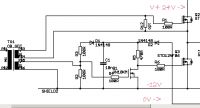
If I could understand your gate driver, from Odin, I might have a go at it, although it contains 3 transistors and a dual output winding gate transformer.
I would appreciate it, if you walk us through the circuit and tell us how it works.
Cheers, Finn Hammer
Finn Hammer, Thu May 28 2009, 08:26PM
Steve, Richie
I dont think anyone in their right mind are questioning your collective judgement regarding silicon durability.
Datasheets specify pulse currents to 50Hz, so obviously there is headroom, but for the reasons you mention, there is little incentive to advertise shorter pulses.
Like Richie said @ one meeting in Canbridge: "If you violate specksheet ratings, you are on your own!".
This is true, but on the other side, I have built Museum coils that operate CM600´s into the thousands of amperes for years on end, so I for one feel quite comfortable being on my own there.
Anyway, now that it has been made official that my gate driver totem pole is a _HACK_, let me say that the best reason I have for liking the PNP/NPN output is that I understand it.
If I could understand your gate driver, from Odin, I might have a go at it, although it contains 3 transistors and a dual output winding gate transformer.
I would appreciate it, if you walk us through the circuit and tell us how it works.

Cheers, Finn Hammer
Re: "Thumper"
hvguy, Fri May 29 2009, 04:49AM
I understand the appeal of the totem pole. It's compact, simple, and easy to build. It's not quite that simple to tweak though Honestly, there are very few applications I can justify not using a GDT in. No floating PS, many KV isolation, nearly impossible to break (although I did blow one up once), bipolar, and they won't cause shoot though in a bridge. I understand what Richie says about leakage slowing things down, but this can be easily designed out. There are commercial GDTs with 600V/uS and higher slew rates available. I think putting 18V on your gate in 30ns (obviously there are other variables here, but you get the point) is probably good enough for most apps
I do use direct gate drive in applications where the duty cycle will be changing very rapidly and/or to a high degree (Class D, etc.). GDTs just don't quite cut it here, IMO.
A dual gate drive IC driving a small GDT, which in turn drives a full bridge of Low Rds ON FETs running off a single 20V rail which is then used to drive a large, well designed GDT, could easily match the speed of an N/P-ch setup when driving a CM600. I have even experimented with the concept of an off-line gate driver. I used this to drive CM1000's in my 16" DRSSTC to make +20' arcs with great results. The only problem was the Fo of 70KHz cause excessive dissipation in the painfully slow CM1000's. I've got another big one in the works, though, with an Fo of ~35KHz to resolve this issue.
I'm glad to see the SS stuff has taken off like it has. This whole SSTC/DRSSTC thing still seems so new to me; it’s funny to think I've been working on it for more than a decade It gets even better when I see people who's first TC EVER is SS. I would have never thought people would consider an SS design over a SG design to cut their teeth on...
hvguy, Fri May 29 2009, 04:49AM
Finn Hammer wrote ...
The video showed a current sweep from 50A to 500A.
About gate drive: I am having a very hard time justifying my initial desicion to use opto's and separate gate drivers, when it would be so much simpler to build a nice little semi-high voltage bridge, and drive a step down gate drive transformer.
It is no easy task to configure the totem pole output stage of the driver and get both zero shoot trough as well as high current output ability:
When I slow down the turn on enough to keep shoot trough low, the turn on is prolonged so that the ability to deliver current within the time frame of turning on of the IGBT is impaired.
I will try the old trick with zeners on the gate, which you may recall from the days of the beefy driver.
(didn'd help)
What I _really_ need is a tiny NTC resistor, which could delay the ramp up to miller plateau, then turn low resistance there, to allow fast full turn on.
Well, this is fun anyway, and perhaps I should just make that bridge/gate tranny and get on with it.
Thanks for -your- work. It was the work of pioneers like yourself that got me started.
Cheers, Finn Hammer
I understand the appeal of the totem pole. It's compact, simple, and easy to build. It's not quite that simple to tweak though
 Honestly, there are very few applications I can justify not using a GDT in. No floating PS, many KV isolation, nearly impossible to break (although I did blow one up once), bipolar, and they won't cause shoot though in a bridge. I understand what Richie says about leakage slowing things down, but this can be easily designed out. There are commercial GDTs with 600V/uS and higher slew rates available. I think putting 18V on your gate in 30ns (obviously there are other variables here, but you get the point) is probably good enough for most apps
I do use direct gate drive in applications where the duty cycle will be changing very rapidly and/or to a high degree (Class D, etc.). GDTs just don't quite cut it here, IMO.
A dual gate drive IC driving a small GDT, which in turn drives a full bridge of Low Rds ON FETs running off a single 20V rail which is then used to drive a large, well designed GDT, could easily match the speed of an N/P-ch setup when driving a CM600. I have even experimented with the concept of an off-line gate driver. I used this to drive CM1000's in my 16" DRSSTC to make +20' arcs with great results. The only problem was the Fo of 70KHz cause excessive dissipation in the painfully slow CM1000's. I've got another big one in the works, though, with an Fo of ~35KHz to resolve this issue.
I'm glad to see the SS stuff has taken off like it has. This whole SSTC/DRSSTC thing still seems so new to me; it’s funny to think I've been working on it for more than a decade
 It gets even better when I see people who's first TC EVER is SS. I would have never thought people would consider an SS design over a SG design to cut their teeth on...
Re: "Thumper"
Finn Hammer, Fri May 29 2009, 06:56AM
Decisions,Decisions.
Well I am going to the end with this N/P driver, then I'l try that fancy high voltage full bridge driver with step down gate transformers. I have a nice ferrite part here waiting to get planted on a pcb, which could be used to split the signals.
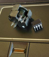
After all, it is simpler that way, trade one full bridge with 4 half bridges.
Cheers, Finn Hammer
Finn Hammer, Fri May 29 2009, 06:56AM
hvguy wrote ...
A dual gate drive IC driving a small GDT, which in turn drives a full bridge of Low Rds ON FETs running of a single 20V rail which is then used to drive a large, well designed GDT, could easily match the speed of and N/P-ch setup when driving a CM600. I have even experimented with the concept of an off-line gate driver. I used this to drive CM1000's in my 16" DRSSTC to make +20' arcs with great results. The only problem was the Fo of 70KHz cause excessive dissipation in the painfully slow CM1000's. I've got another big one is the works though with a Fo of ~35KHz so resolve this issue.
A dual gate drive IC driving a small GDT, which in turn drives a full bridge of Low Rds ON FETs running of a single 20V rail which is then used to drive a large, well designed GDT, could easily match the speed of and N/P-ch setup when driving a CM600. I have even experimented with the concept of an off-line gate driver. I used this to drive CM1000's in my 16" DRSSTC to make +20' arcs with great results. The only problem was the Fo of 70KHz cause excessive dissipation in the painfully slow CM1000's. I've got another big one is the works though with a Fo of ~35KHz so resolve this issue.
Decisions,Decisions.
Well I am going to the end with this N/P driver, then I'l try that fancy high voltage full bridge driver with step down gate transformers. I have a nice ferrite part here waiting to get planted on a pcb, which could be used to split the signals.

After all, it is simpler that way, trade one full bridge with 4 half bridges.
Cheers, Finn Hammer
Re: "Thumper"
hvguy, Fri May 29 2009, 07:22AM
Well, you definitely of a ton of options
Steve W.'s "new" driver with a N/P full bridge uses a creative boot strap arrangement that may be worth looking into if you haven't already. Also, as i'm sure you know, finding a good set of matched part numbers helps. There are so many different brands/ratings to chose from it can be hard to find a "good" complementary pair.
Steve's driver:
hvguy, Fri May 29 2009, 07:22AM
Well, you definitely of a ton of options

Steve W.'s "new" driver with a N/P full bridge uses a creative boot strap arrangement that may be worth looking into if you haven't already. Also, as i'm sure you know, finding a good set of matched part numbers helps. There are so many different brands/ratings to chose from it can be hard to find a "good" complementary pair.
Steve's driver:

Re: "Thumper"
Steve Conner, Fri May 29 2009, 09:12AM
Maybe I was a little mean about the N/P circuit. But the one thing I still don't like about it is that the gate driver is referenced to the 0V rail, whereas the gate of the P-FET is referenced to the supply rail. This change of reference means that any noise on the supply rail (ringing from transients etc) could be amplified by the P-FET as if it was gate drive. This is a potential source of instability, so, good decoupling of the supply rail is uber important.
Finn, a good starting point might be to put capacitors across those zeners. Also, you can have my set of Odin drivers and the power supply to play with if you want them. They were designed to work with my PLL system, but I don't see any reason why they shouldn't work with a Steve Ward driver. Condition, you must rename your coil to Odin The Ball-Thumper
How the circuit works: It's basically a normal half-bridge, except that the low-side MOSFET is driven through an intermediate small FET, which inverts the signal. The phase of the low-side GDT winding is reversed to compensate this inversion.
The reason for this is to make sure that the low-side MOSFET stays on in the absence of any gate drive, clamping the main IGBT securely off. If I just drove both FETs straight from the GDT, then they would both be off in between bursts, leaving the main IGBT gate floating.
As a side benefit, this intermediate stage turns the low-side FET off somewhat faster than it turns it on, which helps to prevent shoot-through.
The diodes D1 and D2 provide two alternate sources of power for this little FET circuit: the main power supply, and a rectified sample of the gate drive. This prevents a spectacular failure mode that I found: if the power supply fails but the gate drive continues, then the high-side FET carries on working, but the low-side one dies. The result is that all four main IGBTs got turned on at once.
More discussion of this driver here:
Steve Conner, Fri May 29 2009, 09:12AM
Maybe I was a little mean about the N/P circuit. But the one thing I still don't like about it is that the gate driver is referenced to the 0V rail, whereas the gate of the P-FET is referenced to the supply rail. This change of reference means that any noise on the supply rail (ringing from transients etc) could be amplified by the P-FET as if it was gate drive. This is a potential source of instability, so, good decoupling of the supply rail is uber important.
Finn, a good starting point might be to put capacitors across those zeners. Also, you can have my set of Odin drivers and the power supply to play with if you want them. They were designed to work with my PLL system, but I don't see any reason why they shouldn't work with a Steve Ward driver. Condition, you must rename your coil to Odin The Ball-Thumper

How the circuit works: It's basically a normal half-bridge, except that the low-side MOSFET is driven through an intermediate small FET, which inverts the signal. The phase of the low-side GDT winding is reversed to compensate this inversion.
The reason for this is to make sure that the low-side MOSFET stays on in the absence of any gate drive, clamping the main IGBT securely off. If I just drove both FETs straight from the GDT, then they would both be off in between bursts, leaving the main IGBT gate floating.
As a side benefit, this intermediate stage turns the low-side FET off somewhat faster than it turns it on, which helps to prevent shoot-through.
The diodes D1 and D2 provide two alternate sources of power for this little FET circuit: the main power supply, and a rectified sample of the gate drive. This prevents a spectacular failure mode that I found: if the power supply fails but the gate drive continues, then the high-side FET carries on working, but the low-side one dies. The result is that all four main IGBTs got turned on at once.
More discussion of this driver here:

Re: "Thumper"
GeordieBoy, Fri May 29 2009, 12:54PM
The "step-down" GDT drive method is a very good technique for driving highly capacitive devices, (or parallel combinations of devices.)
It is particularly effective when the GDT is placed very close to the IGBT brick / MOSFETs being driven. The transformation property of the GDT steps down the drive voltage but steps up the drive current by the same ratio. This means that you can get lots of amps available right at the device's gate terminal. It transforms the gate impedance by the square of the turns ratio. Meaning that if you have an 8nF Cg device and a 4:1 GDT, the effective capacitance seen at the drive side is only 500pF.
A drive circuit using the same 4:1 GDT is also 16 times more tolerant of any stray-inductance on the drive side (primary) of the GDT than the secondary side. This means that it should be placed right on top of the gates being driven, but longer twisted pairs can be tolerated on the primary side running back to the driver circuitry.
Finally it is worth remembering that lightening fast isn't always best. In general turn-off should be faster than turn-on. This is because when a device turns off the current it was carrying is handed to a diode. Conversely when a device turns on it grabs the load current from a diode. In general diodes are much faster at turning on than they are at turning off. In other words you can usually turn off a MOSFET or IGBT as quickly as possible with little fear that the diode might not turn on fast enough and catch the current. The opposite cannot be said, however. Diodes are slow to turn-off and therefore it is not a good idea to turn on a switch too quickly otherwise there will be a horrendous surge of reverse-recovery current through both devices.
In a DRSSTC circuit there is the added quirk that the load current is sinusoidal. This means that if you switch your devices somewhere close to the zero current crossings things should be less critical in terms of power dissipation. It also means that the device being turned on can be done so at a more leisurely pace. As the load current rises the device only needs to be turned on sufficiently to support the instantaneous load current that is flowing. As time passes and the sinewave load current builds, then the device needs to be enhanced futher and further to prevent de-saturation.
Getting this turn-on rate just right gives the holy grail of power electronics:
1. The coolest possible device temperatures
2. The cleanest switching waveforms
3. The minimum of radiated interference
-Richie,
EDIT: I should clarify that direct gate-drive as in Steve C's circuit is better than via a GDT because you have direct control over the gate in terms of rise and fall times and much less stray inductance between the drive circuit and the actual device gate. However, the "step-down" GDT method is better than a normal 1:1 GDT for the reasons discussed.
Re: "Thumper"
Finn Hammer, Fri May 29 2009, 06:03PM
I have 330µF sitting less than 10mm (3/8") from the zeners. These are of course referenced to the groundplane on top of the board. Then the Opto has 2 x 100nF each going from rails to ground plane, with only 2,54mm (1/10") from supply pins to caps.. Finally, the source legs of poth MosFets each have a 47µF low esr surface mount tantalum, again referenced to ground and never more than 5mm from the pins. Pcb is 105µ, so able to carry current. Does that bypass scheme sound reasonable to you?
That is a sweet offer, and I hope you will leave it open for later. Reason: I have to learn from any mistakes I make. If this coil fails, then I'd love to make Odin come true. Only condition: Since you hurt me so, with the ghetto remarks (here where I thought I was being elegant) The coils name is Odin the Ghetto Blaster. It's a good name and about time to name good Ole Odin something contemporary. They weren't whimps, those old gods.
Thanks for that explanation. It was in particular the 2 diodes and the 100nF cap that had me puzzeled.
Cheers, Finn Hammer
Finn Hammer, Fri May 29 2009, 06:03PM
Steve McConner wrote ...
Finn, a good starting point might be to put capacitors across those zeners.
Finn, a good starting point might be to put capacitors across those zeners.
I have 330µF sitting less than 10mm (3/8") from the zeners. These are of course referenced to the groundplane on top of the board. Then the Opto has 2 x 100nF each going from rails to ground plane, with only 2,54mm (1/10") from supply pins to caps.. Finally, the source legs of poth MosFets each have a 47µF low esr surface mount tantalum, again referenced to ground and never more than 5mm from the pins. Pcb is 105µ, so able to carry current. Does that bypass scheme sound reasonable to you?
Steve McConner wrote ...
Also, you can have my set of Odin drivers and the power supply to play with if you want them. They were designed to work with my PLL system, but I don't see any reason why they shouldn't work with a Steve Ward driver. Condition, you must rename your coil to Odin The Ball-Thumper
Also, you can have my set of Odin drivers and the power supply to play with if you want them. They were designed to work with my PLL system, but I don't see any reason why they shouldn't work with a Steve Ward driver. Condition, you must rename your coil to Odin The Ball-Thumper

That is a sweet offer, and I hope you will leave it open for later. Reason: I have to learn from any mistakes I make. If this coil fails, then I'd love to make Odin come true. Only condition: Since you hurt me so, with the ghetto remarks (here where I thought I was being elegant) The coils name is Odin the Ghetto Blaster. It's a good name and about time to name good Ole Odin something contemporary. They weren't whimps, those old gods.

Steve McConner wrote ...
How the circuit works: It's basically a normal half-bridge, except that the low-side MOSFET is driven through an intermediate small FET, which inverts the signal. The phase of the low-side GDT winding is reversed to compensate this inversion.
The reason for this is to make sure that the low-side MOSFET stays on in the absence of any gate drive, clamping the main IGBT securely off. If I just drove both FETs straight from the GDT, then they would both be off in between bursts, leaving the main IGBT gate floating.
As a side benefit, this intermediate stage turns the low-side FET off somewhat faster than it turns it on, which helps to prevent shoot-through.
The diodes D1 and D2 provide two alternate sources of power for this little FET circuit: the main power supply, and a rectified sample of the gate drive. This prevents a spectacular failure mode that I found: if the power supply fails but the gate drive continues, then the high-side FET carries on working, but the low-side one dies. The result is that all four main IGBTs got turned on at once.
More discussion of this driver here:

Thanks for that explanation. It was in particular the 2 diodes and the 100nF cap that had me puzzeled.
Cheers, Finn Hammer
Re: "Thumper"
Dr. Drone, Fri May 29 2009, 06:38PM

Dr. Drone, Fri May 29 2009, 06:38PM

Re: "Thumper"
Steve Conner, Sat May 30 2009, 01:23PM
Hi guys,
Finn, I didn't mean to dis your implementation of the N/P circuit. I think it's pretty good as implementations of it go: I've seen a few builders of it who didn't understand any of the issues raised in this thread, and came to the (old) forum with questions like, "It draws 12 amps from the supply, I lose AM radio reception and the MOSFETs catch fire, what am I doing wrong?"
It's the circuit itself I have the issue with, not your implementation. If you keep tweaking it carefully, I'm sure it'll work fine.
About the Odin gate drivers, they're not going anywhere

Re: "Thumper"
Finn Hammer, Sat May 30 2009, 07:33PM
Steve, all,
Thanks for saying that, Steve.
But hey guys! I think we are having a blast here, good shop humor. I am not offended in any way, only pretending in an attempt to play funny. It's ok with a slightly rough tone, I can handle that.
Now, The Ghetto driver, the hack!
Present status is as sitting on the bench, screwed onto a presumably good CM600 , and undergoing examination of key waveforms.
The tek P6021/134 is monitoring current between MosFets, which means it monitors shoot trough when gate voltage drops (as if there was any), and current into gate when gate voltage rises.
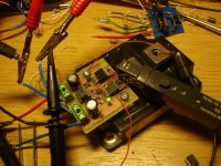
And as such, here is the big picture:
Yellow is gate voltage on CM600, -10V/+20V, 1Volt overshoot, no gate resistor.
Magentha is signal into optocoupler.
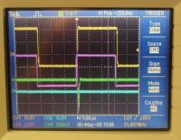
But let's have a closer look.
On the rising edge of the CM600 gate voltage, you can see that voltage is being ramped up from -10V to -2V over 200nS, and then it shoots up to +20V in 100nS. No ringing but 1V overshoot. No gate resistor.
No miller plateou
Current is green, 4A/div, peaks @10A.
Cyan is signal out of opto.
The delay is massive, 300nS for the opto to react, another 300nS for the totem pole to switch, total: 600nS from gate signal into opto, before the CM600 is on. More about this later.
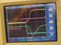
On the falling edge:
Again, no ringing but delays are:
400nS for the opto to react, 300nS for the totem pole to switch, in all 700nS delay.
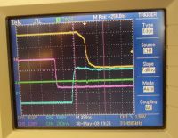
The delays are the drawbacks of this driver, and would render it useless in any other DRSSTC but this one: I can dial this delay in when I set the predikter.
The neat thing is that it switches very cleanly, there are no ringing worth mentioning, no overshoot and no gate resistor to tame things. A word like synergy comes to mind, byt I am probably just talking rubbish.
During the day, I have logged 5 hours of continous CW on it, and it runs slightly hot under CW conditions, which means that in pulsed mode it will run stone cold.
I think I'l use it despite the delays but due to the clean switching and because I designed it myself.
Cheers, Finn Hammer
Finn Hammer, Sat May 30 2009, 07:33PM
Steve, all,
Thanks for saying that, Steve.
But hey guys! I think we are having a blast here, good shop humor. I am not offended in any way, only pretending in an attempt to play funny. It's ok with a slightly rough tone, I can handle that.
Now, The Ghetto driver, the hack!
Present status is as sitting on the bench, screwed onto a presumably good CM600
 , and undergoing examination of key waveforms.
The tek P6021/134 is monitoring current between MosFets, which means it monitors shoot trough when gate voltage drops (as if there was any), and current into gate when gate voltage rises.

And as such, here is the big picture:
Yellow is gate voltage on CM600, -10V/+20V, 1Volt overshoot, no gate resistor.
Magentha is signal into optocoupler.

But let's have a closer look.
On the rising edge of the CM600 gate voltage, you can see that voltage is being ramped up from -10V to -2V over 200nS, and then it shoots up to +20V in 100nS. No ringing but 1V overshoot. No gate resistor.
No miller plateou
Current is green, 4A/div, peaks @10A.
Cyan is signal out of opto.
The delay is massive, 300nS for the opto to react, another 300nS for the totem pole to switch, total: 600nS from gate signal into opto, before the CM600 is on. More about this later.

On the falling edge:
Again, no ringing but delays are:
400nS for the opto to react, 300nS for the totem pole to switch, in all 700nS delay.

The delays are the drawbacks of this driver, and would render it useless in any other DRSSTC but this one: I can dial this delay in when I set the predikter.
The neat thing is that it switches very cleanly, there are no ringing worth mentioning, no overshoot and no gate resistor to tame things. A word like synergy comes to mind, byt I am probably just talking rubbish.
During the day, I have logged 5 hours of continous CW on it, and it runs slightly hot under CW conditions, which means that in pulsed mode it will run stone cold.
I think I'l use it despite the delays but due to the clean switching and because I designed it myself.
Cheers, Finn Hammer
Re: "Thumper"
Dr. Drone, Sat May 30 2009, 07:44PM

Dr. Drone, Sat May 30 2009, 07:44PM

Re: "Thumper"
hvguy, Sun May 31 2009, 08:08AM
Those are some great looking waveforms, and that's a nice dense layout. I can't wait to see how this all plays out once the coil is running. What did you have in mind for a high side PS? Also, I have to agree with the Dr., I use 200V FETs where ever possible simply for higher reliability and transient ruggedness. I know your using 100V parts here, they will probably be fine, especially with such tame switching speeds.
Just for the purposes of comparison, here are a few waveforms I pulled out of my "archive" from my off line gate driver driving a CM1000.
Blue trace is drive input
Green trace is the gate of the CM1000 at 5V/div

Note the overshoot from the small, but still there, leakage L of my custom 9:1:1:1:1 GDT. This is a problem you certainly don't have

Here we see the rise time, about 100ns to zero, 25ns to the miller, and another 75ns to the top (just barely clipped on the screen). The delay appears to be about 150ns. The circuit was designed specifically to keep this delay as small as possible since the parts where already so slow.
Not quite as pretty as yours, but considering the 220nF gate capacitance, I was very happy with these results I should also note that these screen shots where taken while the system was running at low power (about 5KW).
hvguy, Sun May 31 2009, 08:08AM
Those are some great looking waveforms, and that's a nice dense layout. I can't wait to see how this all plays out once the coil is running. What did you have in mind for a high side PS? Also, I have to agree with the Dr., I use 200V FETs where ever possible simply for higher reliability and transient ruggedness. I know your using 100V parts here, they will probably be fine, especially with such tame switching speeds.
Just for the purposes of comparison, here are a few waveforms I pulled out of my "archive" from my off line gate driver driving a CM1000.
Blue trace is drive input
Green trace is the gate of the CM1000 at 5V/div

Note the overshoot from the small, but still there, leakage L of my custom 9:1:1:1:1 GDT. This is a problem you certainly don't have


Here we see the rise time, about 100ns to zero, 25ns to the miller, and another 75ns to the top (just barely clipped on the screen). The delay appears to be about 150ns. The circuit was designed specifically to keep this delay as small as possible since the parts where already so slow.
Not quite as pretty as yours, but considering the 220nF gate capacitance, I was very happy with these results
 I should also note that these screen shots where taken while the system was running at low power (about 5KW).
Re: "Thumper"
Finn Hammer, Mon Jun 01 2009, 08:09AM
Aron,
Thanks for posting your gate waveforms. I have often missed those to compare my work with the reality of others.
Are you averaging the signal to clean the trace up? Mine are a bit more fuzzy.
Going to be interesting to see how they react to a CM600 under load.
High side PSU?. I guess a Mazilli and a flyback core, like on the CCPS. It works well, and is not too stiff, so the V-Reg. Zeners stay cool.
Daniel is going to get the first prototype predikter board for a coil he is building for his work at Aalborg University, and it will be driving an intermediate full bridge, to drive the SKM 400GB124D power bridge. So we may be seing the first results on that coil.
I have just started drilling the heatsink for the CM600 bridge, so it will soon be available for preliminary testing.
Jeez, can't wait to be able to pass 1+kA without worrying about the bridge failing due to over current.
I am also awfully tempted to buy one of these:

So if you would please all step back and don't bid against me
Cheers, Finn Hammer
Finn Hammer, Mon Jun 01 2009, 08:09AM
Aron,
Thanks for posting your gate waveforms. I have often missed those to compare my work with the reality of others.
Are you averaging the signal to clean the trace up? Mine are a bit more fuzzy.
Going to be interesting to see how they react to a CM600 under load.
High side PSU?. I guess a Mazilli and a flyback core, like on the CCPS. It works well, and is not too stiff, so the V-Reg. Zeners stay cool.
Daniel is going to get the first prototype predikter board for a coil he is building for his work at Aalborg University, and it will be driving an intermediate full bridge, to drive the SKM 400GB124D power bridge. So we may be seing the first results on that coil.
I have just started drilling the heatsink for the CM600 bridge, so it will soon be available for preliminary testing.
Jeez, can't wait to be able to pass 1+kA without worrying about the bridge failing due to over current.
I am also awfully tempted to buy one of these:

So if you would please all step back and don't bid against me

Cheers, Finn Hammer
Re: "Thumper"
hvguy, Mon Jun 01 2009, 10:18AM
No problem, Finn. I often whish people would post more waveforms as well. Hopefully the proliferation of inexpensive (relatively) DSO's will help with that in the coming years.
That’s a good question. I do not have anything about it in my notes, but I may have had the bandwidth limit on.
I figured you would go that route for the high side; that driver is just sooo simple, it's really perfect for the task.
Ya, big systems are nice. I have been so much happier with my coils since I started running only 1200V parts and only running them within their DS ratings. I haven't had an IGBT failure in a DRSSTC in at least two years (I think the giant coil was the last one. That $1,100 brick hurt!).
Good luck with that monster inverter assembly. I can only imagine what the came from

Re: "Thumper"
colin heath, Sun Jun 07 2009, 04:03PM
Very informative thread. I think I have understood a little of it at least;-)
Your work is always very thorough Finn and you always strike me as a very organised thinker. (based on your help with my DRSSTC lash up that year at derby)
Keep up the good work while I try and make sense of it all
Re: "Thumper"
Dalus, Sun Jun 07 2009, 04:24PM
It's indeed a very good informational thread. Think I'll borrow a few things from this thread for my own DRSSTC. Starting to understand the various gate drives and the pros and cons of each type. Though I'm curious to see how much you'd need to slow down the gate driver when driving large slow bricks. Fast isn't always the best option.
But I'm really curious to see how well the delay circuit works and how sensitive it is.
You've done a great job so far Finn Hammer

Re: "Thumper"
Finn Hammer, Sun Jun 07 2009, 08:48PM
Thanks a lot folks, you are being very kind.
I am riding high on a surge of gumption and creativity. Today, I have been making the bus for the bridge, which is now starting to take shape:
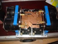
In my urge to tuck the lytics as close as possible into the bridge, I had to do a lot of machining, and next time, the buss plates are going to be extended to both sides, and the caps are going to be mounted vertical instead of horisontal.
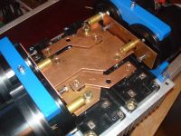
The gate drivers have been completed, and they open the gates "blixt schnell" 200nS and we will see if it is good or bad. Pls. note, that with the "Predikter", there is no need to slow down the turn on for the traditional reason: to allow the other IGBT to shut off. This design features separate timing for the turn off as well as the turn on, and the turn off happens at current zero crossing, right?
So a completely new situation here.
The air core coil forming the predictor information in the load for the current transformer has now been replaced by a 1µH high class magnetically shielded part from Epcos, and it is working flawlessly.
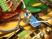
Nice little 10mm x 10mm footprint SMD part.
I've got 3 days off, next week, so lots of progress is anticipated.
Cheers, Finn Hammer
Finn Hammer, Sun Jun 07 2009, 08:48PM
Thanks a lot folks, you are being very kind.
I am riding high on a surge of gumption and creativity. Today, I have been making the bus for the bridge, which is now starting to take shape:

In my urge to tuck the lytics as close as possible into the bridge, I had to do a lot of machining, and next time, the buss plates are going to be extended to both sides, and the caps are going to be mounted vertical instead of horisontal.

The gate drivers have been completed, and they open the gates "blixt schnell" 200nS and we will see if it is good or bad. Pls. note, that with the "Predikter", there is no need to slow down the turn on for the traditional reason: to allow the other IGBT to shut off. This design features separate timing for the turn off as well as the turn on, and the turn off happens at current zero crossing, right?
So a completely new situation here.
The air core coil forming the predictor information in the load for the current transformer has now been replaced by a 1µH high class magnetically shielded part from Epcos, and it is working flawlessly.

Nice little 10mm x 10mm footprint SMD part.

I've got 3 days off, next week, so lots of progress is anticipated.
Cheers, Finn Hammer
Re: "Thumper"
Dalus, Sun Jun 07 2009, 09:15PM
Your H-bridge looks great nice and compact. It would give me nightmares if I had to use single IGBT modules. Halfbridge modules together with some angle iron give a way simpler layout. I also had the urge to mount my lyctics sideways and almost on the igbt's
Dalus, Sun Jun 07 2009, 09:15PM
Your H-bridge looks great nice and compact. It would give me nightmares if I had to use single IGBT modules. Halfbridge modules together with some angle iron give a way simpler layout. I also had the urge to mount my lyctics sideways and almost on the igbt's

Re: "Thumper"
Finn Hammer, Tue Jun 09 2009, 08:59PM
Just a couple of pretty pictures before I crash.
First the busswork, now all finished, and with copper risers for connection to primary circuit. These risers will go trough the current feedback transformers.
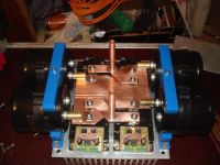
Next, just to show how I intend to wrap it all up:
A nice alluminium box to contain the "Predikter" driver board, just finished soldering the 2nd. version with major bug fixes.
Nice short wires protruding with gate drive signals. They are not there yet, just in case you wonder.
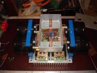
I ordered the box a little small, another one is in the mail.
So it is going to become a nice compact motor for the "MK4"
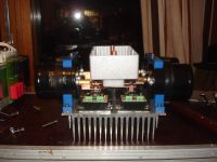
Cheers, Finn Hammer
Finn Hammer, Tue Jun 09 2009, 08:59PM
Just a couple of pretty pictures before I crash.
First the busswork, now all finished, and with copper risers for connection to primary circuit. These risers will go trough the current feedback transformers.

Next, just to show how I intend to wrap it all up:
A nice alluminium box to contain the "Predikter" driver board, just finished soldering the 2nd. version with major bug fixes.
Nice short wires protruding with gate drive signals. They are not there yet, just in case you wonder.


I ordered the box a little small, another one is in the mail.
So it is going to become a nice compact motor for the "MK4"

Cheers, Finn Hammer
Re: "Thumper"
Extreme Electronics, Tue Jun 09 2009, 09:51PM
Fantastic engineering as always Finn. Although it would be a great shame to hide that Bridge in an aluminium case. Someone must make conductive plexy ;)
Derek
Extreme Electronics, Tue Jun 09 2009, 09:51PM
Fantastic engineering as always Finn. Although it would be a great shame to hide that Bridge in an aluminium case. Someone must make conductive plexy ;)
Derek
Re: "Thumper"
Dalus, Tue Jun 09 2009, 10:06PM
One small thing that you might want to do. If I recall correctly Steve Wards bridge once arced over between two sharp edges on the busbar. You might want to round them just in case. Wouldn't want any destroyed IGBT's
Dalus, Tue Jun 09 2009, 10:06PM
One small thing that you might want to do. If I recall correctly Steve Wards bridge once arced over between two sharp edges on the busbar. You might want to round them just in case. Wouldn't want any destroyed IGBT's

Re: "Thumper"
Finn Hammer, Wed Jun 10 2009, 08:48AM
It consists of plexi with a very fine mesh cast into the top 1/10th of a millimeter. The mesh is invisible to the naked eye of us mortals, excluding birds of prey, perhaps.

But with a magnifying glass it becomes visible to the unwashed masses, even. Problem is getting contact with it: Paint the edges with conductive paint, then interface with that: Not to my liking.
Apart from that, pretty as it is, I never was much into plexi. Apo-plexi, perhaps...
I think Steve was probably having creepage before flashover. Makes a big difference with RF signals of power magnitude.
Cheers, Finn Hammer
Finn Hammer, Wed Jun 10 2009, 08:48AM
Extreme Electronics wrote ...
Fantastic engineering as always Finn. Although it would be a great shame to hide that Bridge in an aluminium case. Someone must make conductive plexy ;)
Derek
They do, actually. And I have a piece of it somewhere in the pile of junk I call my workshop.Fantastic engineering as always Finn. Although it would be a great shame to hide that Bridge in an aluminium case. Someone must make conductive plexy ;)
Derek
It consists of plexi with a very fine mesh cast into the top 1/10th of a millimeter. The mesh is invisible to the naked eye of us mortals, excluding birds of prey, perhaps.

But with a magnifying glass it becomes visible to the unwashed masses, even. Problem is getting contact with it: Paint the edges with conductive paint, then interface with that: Not to my liking.
Apart from that, pretty as it is, I never was much into plexi. Apo-plexi, perhaps...

Dalus wrote ...
One small thing that you might want to do. If I recall correctly Steve Wards bridge once arced over between two sharp edges on the busbar. You might want to round them just in case. Wouldn't want any destroyed IGBT's
One small thing that you might want to do. If I recall correctly Steve Wards bridge once arced over between two sharp edges on the busbar. You might want to round them just in case. Wouldn't want any destroyed IGBT's

I think Steve was probably having creepage before flashover. Makes a big difference with RF signals of power magnitude.
Cheers, Finn Hammer
Re: "Thumper"
Finn Hammer, Thu Jun 11 2009, 07:13PM
What a wonderful day!
Started early after a 24hours shift, downloaded the mazilli schematic from HvWiki, and drew it into eagle.
Got it layed out in Board, printed out the transparancies, and by 11 hours, I had the board, drilled and ready for population.
Stuck the parts in, and tried it out with temporary windings on the pot core transformer: It worked, oscillating at 96kHz.
This is the nice thing about making projects in eagle: They always work 1st. time.
The cuts into the board are to prevent the high side supply from tracking to low side.
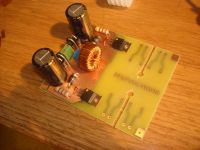
Now it is time to work out the magnetics. I had a nice pot e-core I wanted to try out because it looks really pro and I had to make a custom bobbin for it too, the white one. Separate chambers for each gate supply, some of them bounching up 1200V and back. Well, maby only 1120V
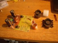
I wound the primary, 2x5turns, with some 0.07mm thin foil I had lying around. And needed to make a really compact primary.
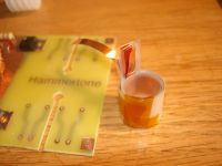
When It was all done, 12 hours had passed, and I was - sort of - satisfied:
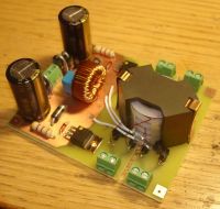
No doubt, due to the tight coupling in this transformer, the output is quite stiff, as opposed to when I used a flyback core, with the primary on one leg and the secondary's on the other legs:
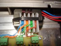
So now I have to find a way to stop frying the shunt zeners on the gate driver boards.
What is the most elegant way to limit the current out of the Mazzilli? Chokes on the driver boards or can it be done with another, bigger value series inductor, the one on the Mazzilli driver that goes to center leg of transformer? I am using one 0.2mH on yellow core. (So many things to know)
Ideas are invited here, cause I can't think or even see straight, having worked for 36 hours on end.
(But a great time was had)
Cheers, Finn hammer.
EDIT!
I s'pose it would be double posting, even though I answer the question myself.
The problem was, that the mazilli could put out considerable current, and that the gate driver board had a capacitor input filter, very crudely regulated by shunt Zeners.
These zeners turned hot very fast when I connected the mazilli to them, so some sort of current limitation had to be found.
The solution I came up with, was to change the filter on the gate driver boards to a choke input filter. In this case, a 1mH inductor did the trick. I had to increase the turns count on the mazilli transformer, from 10 to 15 to get enough voltage on the boards with this new filter, but the good thing is this:
I have full gate drive voltage, -10 - +20 V from 160V line, and up to 240V, where the zeners are still cool.
Another cheers from Denmark!
Finn Hammer, Thu Jun 11 2009, 07:13PM
What a wonderful day!
Started early after a 24hours shift, downloaded the mazilli schematic from HvWiki, and drew it into eagle.
Got it layed out in Board, printed out the transparancies, and by 11 hours, I had the board, drilled and ready for population.
Stuck the parts in, and tried it out with temporary windings on the pot core transformer: It worked, oscillating at 96kHz.
This is the nice thing about making projects in eagle: They always work 1st. time.
The cuts into the board are to prevent the high side supply from tracking to low side.

Now it is time to work out the magnetics. I had a nice pot e-core I wanted to try out because it looks really pro
 and I had to make a custom bobbin for it too, the white one. Separate chambers for each gate supply, some of them bounching up 1200V and back. Well, maby only 1120V

I wound the primary, 2x5turns, with some 0.07mm thin foil I had lying around. And needed to make a really compact primary.

When It was all done, 12 hours had passed, and I was - sort of - satisfied:

No doubt, due to the tight coupling in this transformer, the output is quite stiff, as opposed to when I used a flyback core, with the primary on one leg and the secondary's on the other legs:

So now I have to find a way to stop frying the shunt zeners on the gate driver boards.
What is the most elegant way to limit the current out of the Mazzilli? Chokes on the driver boards or can it be done with another, bigger value series inductor, the one on the Mazzilli driver that goes to center leg of transformer? I am using one 0.2mH on yellow core. (So many things to know)
Ideas are invited here, cause I can't think or even see straight, having worked for 36 hours on end.
(But a great time was had)
Cheers, Finn hammer.
EDIT!
I s'pose it would be double posting, even though I answer the question myself.
The problem was, that the mazilli could put out considerable current, and that the gate driver board had a capacitor input filter, very crudely regulated by shunt Zeners.
These zeners turned hot very fast when I connected the mazilli to them, so some sort of current limitation had to be found.
The solution I came up with, was to change the filter on the gate driver boards to a choke input filter. In this case, a 1mH inductor did the trick. I had to increase the turns count on the mazilli transformer, from 10 to 15 to get enough voltage on the boards with this new filter, but the good thing is this:
I have full gate drive voltage, -10 - +20 V from 160V line, and up to 240V, where the zeners are still cool.
Another cheers from Denmark!
Re: "Thumper"
Finn Hammer, Mon Jun 15 2009, 06:47AM
The board and sch files are here:


All Eagle files, enjoy!
Cheers, Finn Hammer
Finn Hammer, Mon Jun 15 2009, 06:47AM
The board and sch files are here:


All Eagle files, enjoy!
Cheers, Finn Hammer
Re: "Thumper"
Z28Fistergod, Tue Jun 16 2009, 12:27AM
Do you use just one of your inverter digital phase lag circuits? Or do you use one for each leg of the H-Bridge, which would allow you to set some dead time (or overlap)?
Z28Fistergod, Tue Jun 16 2009, 12:27AM
Do you use just one of your inverter digital phase lag circuits? Or do you use one for each leg of the H-Bridge, which would allow you to set some dead time (or overlap)?
Re: "Thumper"
Finn Hammer, Wed Jun 17 2009, 08:56PM
First delay stage arranges ZCS, the next stages set dead time.
Cheers, Finn Hammer
Finn Hammer, Wed Jun 17 2009, 08:56PM
Z28Fistergod wrote ...
Do you use just one of your inverter digital phase lag circuits? Or do you use one for each leg of the H-Bridge, which would allow you to set some dead time (or overlap)?
Do you use just one of your inverter digital phase lag circuits? Or do you use one for each leg of the H-Bridge, which would allow you to set some dead time (or overlap)?
First delay stage arranges ZCS, the next stages set dead time.
Cheers, Finn Hammer
Re: "Thumper"
Finn Hammer, Thu Jun 25 2009, 09:00PM
All,
I just assembled the "Thumper" motor:
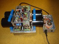
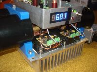
As you see, it is preset for a 6.01kA current limit.
But under initial testing I saw that all the gates were +20V. What a bummer: during design and debug, I ran them from a sig gen. and did oversee the fact, that when the enable pin of the UCC37322 output chips are low, then the output is also low.
The optocouplers demand a current signal to reach high, which turns the gate drivers off.
At present I can´t see any easy or proper way to get around this problem, so maby this is a hint, that I should go for gate transformer after all.
I am tempted, sure would be easier.....
Those gate drivers were not safe. A missing signal should not cause failure.
EDIT.
Come to think of it, a small bipolar could reverse the drive and make it soso.
Maby I will hear the bridge sing tomorrow after all.
Cheers, Finn Hammer
Finn Hammer, Thu Jun 25 2009, 09:00PM
All,
I just assembled the "Thumper" motor:


As you see, it is preset for a 6.01kA current limit.
But under initial testing I saw that all the gates were +20V. What a bummer: during design and debug, I ran them from a sig gen. and did oversee the fact, that when the enable pin of the UCC37322 output chips are low, then the output is also low.
The optocouplers demand a current signal to reach high, which turns the gate drivers off.
At present I can´t see any easy or proper way to get around this problem, so maby this is a hint, that I should go for gate transformer after all.
I am tempted, sure would be easier.....
Those gate drivers were not safe. A missing signal should not cause failure.
EDIT.
Come to think of it, a small bipolar could reverse the drive and make it soso.
Maby I will hear the bridge sing tomorrow after all.

Cheers, Finn Hammer
Re: "Thumper"
Mathias, Fri Jun 26 2009, 06:49AM
Is it a good idea to mount the control electronics so close, in between the output terminals ?
Mathias, Fri Jun 26 2009, 06:49AM
Is it a good idea to mount the control electronics so close, in between the output terminals ?
Re: "Thumper"
Finn Hammer, Fri Jun 26 2009, 04:50PM
Probably not. It is giving me a lot of headache just to make it look good.
Next iteration is not going to look like that, that´s for sure.
Cheers, Finn Hammer
Finn Hammer, Fri Jun 26 2009, 04:50PM
Mathias wrote ...
Is it a good idea to mount the control electronics so close, in between the output terminals ?
Is it a good idea to mount the control electronics so close, in between the output terminals ?
Probably not. It is giving me a lot of headache just to make it look good.
Next iteration is not going to look like that, that´s for sure.
Cheers, Finn Hammer
Re: "Thumper"
Finn Hammer, Sun Jun 28 2009, 02:42PM
With a couple of more hacks, I finally got the bridge up and-a hummin.
With 1.2uS combined delays from switching command issued to switching accomplished, it is still possible to acheive switching without overshoot and ringing, as I have documented with this little video.

Enjoy, Finn Hammer
Finn Hammer, Sun Jun 28 2009, 02:42PM
With a couple of more hacks, I finally got the bridge up and-a hummin.
With 1.2uS combined delays from switching command issued to switching accomplished, it is still possible to acheive switching without overshoot and ringing, as I have documented with this little video.

Enjoy, Finn Hammer
Re: "Thumper"
GeordieBoy, Sun Jun 28 2009, 04:06PM
Really excellent work Finn! The video is very informative. I would recommend anyone interested in Solid-State Tesla Coils to check it out.
It shows very dramatically how eliminating the reverse-recovery spikes of the co-pack diodes eliminates the resulting overshoot and ringing on the voltage waveform.
The only thing you have to watch out for is advancing the timing too much! Eventually you will see little steps form at the beginning of the voltage waveform, right after the transition. This is a little step downwards right where all the ringing used to be. If this step exists this indicates that the IGBTs are turning off before the zero-crossing of the current. The length of the step indicates how far ahead of the current-zero the IGBT turned off. This is generally bad for slow IGBTs because of current tailing when interrupting large collector currents. In practice it equates to increased switching losses at turn-off.
So, switching too late you have, reverse-recovery spikes, lots of ringing and turn-on switching losses. Or switching too early you have turn-off switching losses due to current tailing in the IGBTs. Obviously the sweet spot is where the IGBTs turn off with almost no current flowing at all, and the next device turns on right at the zero current crossing or very soon afterwards.
I shall follow your further developments with interest.
-Richie,
Re: "Thumper"
Dr. Drone, Sun Jun 28 2009, 05:11PM

Dr. Drone, Sun Jun 28 2009, 05:11PM

Re: "Thumper"
Finn Hammer, Sun Jun 28 2009, 06:11PM
I was just about to ask about the "dreaded current tail", one concept that I have not fully grasped. I will take a closer look at the waveforms to investigate this further.
Thanks!
You are absolutely right, but you know there is a bit of Clint Eastwood in me, and I couldn´t resist going "whole hog" with that video.
I will use at least TVZ´s as snubber fer sure.
I am planning a test snubber, where I use a string of TVZ´s, one with a small value at the top, so like 1000V, and a 7.5V one on the top.
When this string starts to conduct, there will be 7.5 volts across the top TVZ, and enough current to drive a LED with associated resistor.
This could be used to show if there are overshoots, and at what input voltage level,
Could even make a small battery powered board with a 555 to make longer, more visible diode flashes.
But sure, the production version will have belt and braces protection.
Cheers, Finn Hammer
Finn Hammer, Sun Jun 28 2009, 06:11PM
GeordieBoy wrote ...
Really excellent work Finn! The video is very informative. I would recommend anyone interested in Solid-State Tesla Coils to check it out.
It shows very dramatically how eliminating the reverse-recovery spikes of the co-pack diodes eliminates the resulting overshoot and ringing on the voltage waveform.
The only thing you have to watch out for is advancing the timing too much! Eventually you will see little steps form at the beginning of the voltage waveform, right after the transition. This is a little step downwards right where all the ringing used to be. If this step exists this indicates that the IGBTs are turning off before the zero-crossing of the current. The length of the step indicates how far ahead of the current-zero the IGBT turned off. This is generally bad for slow IGBTs because of current tailing when interrupting large collector currents. In practice it equates to increased switching losses at turn-off.
So, switching too late you have, reverse-recovery spikes, lots of ringing and turn-on switching losses. Or switching too early you have turn-off switching losses due to current tailing in the IGBTs. Obviously the sweet spot is where the IGBTs turn off with almost no current flowing at all, and the next device turns on right at the zero current crossing or very soon afterwards.
I shall follow your further developments with interest.
-Richie,
Thanks.Really excellent work Finn! The video is very informative. I would recommend anyone interested in Solid-State Tesla Coils to check it out.
It shows very dramatically how eliminating the reverse-recovery spikes of the co-pack diodes eliminates the resulting overshoot and ringing on the voltage waveform.
The only thing you have to watch out for is advancing the timing too much! Eventually you will see little steps form at the beginning of the voltage waveform, right after the transition. This is a little step downwards right where all the ringing used to be. If this step exists this indicates that the IGBTs are turning off before the zero-crossing of the current. The length of the step indicates how far ahead of the current-zero the IGBT turned off. This is generally bad for slow IGBTs because of current tailing when interrupting large collector currents. In practice it equates to increased switching losses at turn-off.
So, switching too late you have, reverse-recovery spikes, lots of ringing and turn-on switching losses. Or switching too early you have turn-off switching losses due to current tailing in the IGBTs. Obviously the sweet spot is where the IGBTs turn off with almost no current flowing at all, and the next device turns on right at the zero current crossing or very soon afterwards.
I shall follow your further developments with interest.
-Richie,
I was just about to ask about the "dreaded current tail", one concept that I have not fully grasped. I will take a closer look at the waveforms to investigate this further.
Thanks!
Dr. Spark wrote ...
Nice work sir!
The video documentation is great. Only issue I had is there was this face in there that could scare the newbie’s to death!
Still thinking a snubber with diode/resistor would be a safe measure just in case. Will not switch in 99% of the time, but that one time when things get crazy.
Cannot wait to see your Fatboy ripping indeed!
Spark On,
Christopher
You are absolutely right, but you know there is a bit of Clint Eastwood in me, and I couldn´t resist going "whole hog" with that video.
I will use at least TVZ´s as snubber fer sure.
I am planning a test snubber, where I use a string of TVZ´s, one with a small value at the top, so like 1000V, and a 7.5V one on the top.
When this string starts to conduct, there will be 7.5 volts across the top TVZ, and enough current to drive a LED with associated resistor.
This could be used to show if there are overshoots, and at what input voltage level,
Could even make a small battery powered board with a 555 to make longer, more visible diode flashes.
But sure, the production version will have belt and braces protection.
Cheers, Finn Hammer
Re: "Thumper"
hvguy, Sun Jun 28 2009, 06:28PM
Nice video Finn. I will have to apply this to future projects.
Your relatively quick progress with this and ultimately its successful implementation got me thinking. Why did mine have so much phase shift variation? I went through my junk boxes and found the test setup from years ago, hooked it up, and sure enough, there was several degrees of phase change just by varying the current. Since yours did not behave this way I looked into it further. I had tried many different resistors and CTs but I always used the same small variable inductor. Since it was the only constant I removed it from the circuit and checked it with my LC meter and the inductance variation was nowhere near linear. I took the can off and, to my surprise, found shorted turns! Arggg, this whole time I thought the circuit was the problem! I recall accidentally running it without a burden a few times; I must have flashed over a few of those tiny turns... so much wasted time!
I’m glad you brought this concept back into light or I may never have revisited it, thinking my original results where accurate. I can’t wait to try it out now… Also, if you wanted to prevent the problems caused by too much phase lead, you could always use a simple phase comparator and leds. Maybe even a three led arrangement in a lead-0-lag configuration. You could also incorporate a shut down circuit feed from this comparator.
Re: "Thumper"
Linas, Sun Jun 28 2009, 06:48PM
i don't know, or it good idea, but or someone try LC (like in induction heater) topology for DRSSTC ?
One of mine friend says , that if you using LC in series, you have large current in IGBT without any sense. So it can solve LC circuit...
Linas, Sun Jun 28 2009, 06:48PM
i don't know, or it good idea, but or someone try LC (like in induction heater) topology for DRSSTC ?
One of mine friend says , that if you using LC in series, you have large current in IGBT without any sense. So it can solve LC circuit...

Re: "Thumper"
Steve Conner, Sun Jun 28 2009, 07:45PM
Hey Finn, looks sweet! My only worry with these lead networks was that, being differentiators, they would amplify any high frequency noise floating around the circuit. But if it works it works, I won't argue with a working circuit.
Oh, and if newbies find your face scary, they're too weak to face terrifying sparks from a Tesla coil, so I say bring it on "I don't use snubbahs any moah"
Steve Conner, Sun Jun 28 2009, 07:45PM
Hey Finn, looks sweet! My only worry with these lead networks was that, being differentiators, they would amplify any high frequency noise floating around the circuit. But if it works it works, I won't argue with a working circuit.
Oh, and if newbies find your face scary, they're too weak to face terrifying sparks from a Tesla coil, so I say bring it on
 "I don't use snubbahs any moah"
Re: "Thumper"
Finn Hammer, Sun Jun 28 2009, 08:36PM
Actually, the shunt resistors across the lead burden inductor are there to dampen noise.
With the buss ringing like the liberty bell, initially the noice creates havoc in the circuit. Well, really it operates stable enough even then, but the scope is full of "tall grass" on all signals right at IGBT turn on time.
But when ZCS is dialled in, scope becomes nice and calm.
This will keep the whatshammacallthem? the EMC guys? happy.
"This coil only emits noise from the streamers"
Cheers, Finn Hammer
Finn Hammer, Sun Jun 28 2009, 08:36PM
Steve McConner wrote ...
Hey Finn, looks sweet! My only worry with these lead networks was that, being differentiators, they would amplify any high frequency noise floating around the circuit. But if it works it works, I won't argue with a working circuit.
Oh, and if newbies find your face scary, they're too weak to face terrifying sparks from a Tesla coil, so I say bring it on "I don't use snubbahs any moah"
Hey Finn, looks sweet! My only worry with these lead networks was that, being differentiators, they would amplify any high frequency noise floating around the circuit. But if it works it works, I won't argue with a working circuit.
Oh, and if newbies find your face scary, they're too weak to face terrifying sparks from a Tesla coil, so I say bring it on
 "I don't use snubbahs any moah"
 Actually, the shunt resistors across the lead burden inductor are there to dampen noise.
With the buss ringing like the liberty bell, initially the noice creates havoc in the circuit. Well, really it operates stable enough even then, but the scope is full of "tall grass" on all signals right at IGBT turn on time.
But when ZCS is dialled in, scope becomes nice and calm.
This will keep the whatshammacallthem? the EMC guys? happy.
"This coil only emits noise from the streamers"
Cheers, Finn Hammer
Re: "Thumper"
Finn Hammer, Sat Jul 04 2009, 05:48PM
all,
I now converted the motor to transformer gate drive. An intermediate 80V bridge drives 2pcs. 4:1 gate transformers.
I have boasted that I don´t use snubbas anymore, but to not appear foolhardy, I put 1000V strings of TVS'es.
This brings this cluttered look, Hats off to Linas for his clean looking bridge.
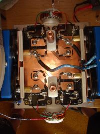
The motor is then dressed up with the box of controll electronics, the much fabled Hammertone "Predikter", and then it looks like this, where you can also catch a glimpse of the bench load we use to test the motor against:
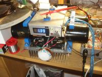
With 15ohm gate resistance, the sweet spot was met, where there is virtually no overshoot, particularly when power is cranked up!

Enjoy, Finn Hammer
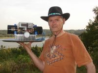
Finn Hammer, Sat Jul 04 2009, 05:48PM
all,
I now converted the motor to transformer gate drive. An intermediate 80V bridge drives 2pcs. 4:1 gate transformers.
I have boasted that I don´t use snubbas anymore, but to not appear foolhardy, I put 1000V strings of TVS'es.
This brings this cluttered look, Hats off to Linas for his clean looking bridge.

The motor is then dressed up with the box of controll electronics, the much fabled Hammertone "Predikter", and then it looks like this, where you can also catch a glimpse of the bench load we use to test the motor against:

With 15ohm gate resistance, the sweet spot was met, where there is virtually no overshoot, particularly when power is cranked up!


Enjoy, Finn Hammer

Re: "Thumper"
Finn Hammer, Mon Jul 06 2009, 10:30AM
All,
So we finally had first light.
After a week end with many tasks, amongst the construction of a 3-phase voltage quadrupler, we set the rather hastily constructed primary coil up.
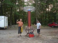
Firing up the coil, it became clear that it favours low break rates, and that tuning a big coil like this is not at all easy. Over current limit stayed at 2kA...
Starting out thinking we´d break records, we soon realized that with 10 feet on the chart, we had better wrap the coil up and let the experience sink in....
We did a small video documentary.
Distance from breakout point to ladder is 3 meters, and to ground 3.10 meters

Cheers, Finn Hammer and Daniel Uhrenholt
Finn Hammer, Mon Jul 06 2009, 10:30AM
All,
So we finally had first light.
After a week end with many tasks, amongst the construction of a 3-phase voltage quadrupler, we set the rather hastily constructed primary coil up.

Firing up the coil, it became clear that it favours low break rates, and that tuning a big coil like this is not at all easy. Over current limit stayed at 2kA...
Starting out thinking we´d break records, we soon realized that with 10 feet on the chart, we had better wrap the coil up and let the experience sink in....
We did a small video documentary.
Distance from breakout point to ladder is 3 meters, and to ground 3.10 meters

Cheers, Finn Hammer and Daniel Uhrenholt
Re: "Thumper"
Dalus, Mon Jul 06 2009, 07:38PM
Wow that has some Thump to it From the looks of it your coil will surely to break some records. Guess it's time for you guys to clean it up and build it so it's ready for some more demos. That test must have been loud.
Can you give some more info, power usage bus voltage etc. Quite curious to see how your coil preforms compared to others.
I'd say it's safe to go a bit further current wise, 2kA should be quite safe for the CM600 IGBTs to handle. (short version we want more and bigger arcs )
)
Dalus, Mon Jul 06 2009, 07:38PM
Wow that has some Thump to it
 From the looks of it your coil will surely to break some records. Guess it's time for you guys to clean it up and build it so it's ready for some more demos. That test must have been loud.
 Can you give some more info, power usage bus voltage etc. Quite curious to see how your coil preforms compared to others.
I'd say it's safe to go a bit further current wise, 2kA should be quite safe for the CM600 IGBTs to handle. (short version we want more and bigger arcs
 )
)Re: "Thumper"
Bennem, Mon Jul 06 2009, 08:14PM
.....'if you go down in the woods today your sure for a big surprise'.......lol
Wow Finn, thats quite some spark already!
well done mate!
Mel
Bennem, Mon Jul 06 2009, 08:14PM
.....'if you go down in the woods today your sure for a big surprise'.......lol
Wow Finn, thats quite some spark already!
well done mate!
Mel
Re: "Thumper"
Killa-X, Mon Jul 06 2009, 11:29PM
Yeah, I thought that and the fact that the Thumper is so compacted, that I was looking at his tesla coil thinking, "Wow, There's really not much to setup." Just connect the small thumper to the coil and off you go. Very compacted makes it look really clean and simple.
Nice job on the Thumper tesla though! Really looks nice
Killa-X, Mon Jul 06 2009, 11:29PM
Dalus wrote ...
Wow that has some Thump to it From the looks of it your coil will surely to break some records.
Wow that has some Thump to it
 From the looks of it your coil will surely to break some records.
Yeah, I thought that and the fact that the Thumper is so compacted, that I was looking at his tesla coil thinking, "Wow, There's really not much to setup." Just connect the small thumper to the coil and off you go. Very compacted makes it look really clean and simple.
Nice job on the Thumper tesla though! Really looks nice

Re: "Thumper"
Coronafix, Tue Jul 07 2009, 02:00AM
Nice work fellas!! The coupling looks quite loose on the coil, are you intending to tighten this up?
What is the estimated power limit to the engine? And how much were you driving into it in the vid?
Coronafix, Tue Jul 07 2009, 02:00AM
Nice work fellas!! The coupling looks quite loose on the coil, are you intending to tighten this up?
What is the estimated power limit to the engine? And how much were you driving into it in the vid?
Re: "Thumper"
Linas, Tue Jul 07 2009, 06:37PM

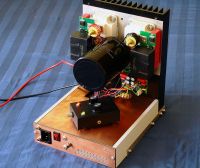
Linas, Tue Jul 07 2009, 06:37PM
Finn Hammer wrote ...
This brings this cluttered look, Hats off to Linas for his clean looking bridge.
Your bridge have better looking, and performance. but hey, mine is working too This brings this cluttered look, Hats off to Linas for his clean looking bridge.


Re: "Thumper"
Finn Hammer, Tue Jul 07 2009, 07:25PM
I really was trying to flatter you with the clean look of your bridge. Like the nice snubber board tucked nicely away, not like my TVS'es and resistors.
Cheers, Finn Hammer
Finn Hammer, Tue Jul 07 2009, 07:25PM
Linas wrote ...

Linas,Finn Hammer wrote ...
This brings this cluttered look, Hats off to Linas for his clean looking bridge.
Your bridge have better looking, and performance. but hey, mine is working too This brings this cluttered look, Hats off to Linas for his clean looking bridge.

I really was trying to flatter you with the clean look of your bridge. Like the nice snubber board tucked nicely away, not like my TVS'es and resistors.
Cheers, Finn Hammer
Re: "Thumper"
vasil, Tue Jul 07 2009, 08:23PM
Good work, very nice results!
I followed your project with great interest, even I dont fully understand all the electronics implied though.
I guess that after more testing there will be "Thumper units" from the Finn' shop avalaible on market. They will run coils in a broad frequency range.
Re: "Thumper"
teravolt, Wed Jul 08 2009, 02:18AM
Finn how much power are you consuming out of the wall and what is your power source
teravolt, Wed Jul 08 2009, 02:18AM
Finn how much power are you consuming out of the wall and what is your power source
Re: "Thumper"
Arcstarter, Wed Jul 08 2009, 03:37AM
Is a very impressive coil indeed! Wow, 3 meter sparks :D.
And are those little film caps on your hat? Either way, nice picture :D. It is somewhat smaller than i imagined. That is sure small for how big those sparks are! IGBT's sure are one of the world's little wonders, aren't they?
Re: "Thumper"
Coronafix, Wed Jul 08 2009, 04:39AM
Lol! That's turquoise. Finn must have picked up that hat while in the U.S., the American Indians like to
work with it a lot.
Coronafix, Wed Jul 08 2009, 04:39AM
Arcstarter wrote ...
And are those little film caps on your hat?
And are those little film caps on your hat?
Lol! That's turquoise. Finn must have picked up that hat while in the U.S., the American Indians like to
work with it a lot.
Re: "Thumper"
Arcstarter, Wed Jul 08 2009, 06:25PM
Arcstarter, Wed Jul 08 2009, 06:25PM
Coronafix wrote ...
Lol! That's turquoise. Finn must have picked up that hat while in the U.S., the American Indians like to
work with it a lot.
I definitely see now that i actually enlarge the pic 0_o.Arcstarter wrote ...
And are those little film caps on your hat?
And are those little film caps on your hat?
Lol! That's turquoise. Finn must have picked up that hat while in the U.S., the American Indians like to
work with it a lot.
Re: "Thumper"
Paul Benham, Thu Jul 23 2009, 12:47PM
Hi Finn,
You have a reset IC on the 15V rail that shuts down the drive if the supply fails. I wondered what this IC was that you used?
Cheers,
Paul.
Edit - I now realise that what I thought to be a reset IC is the Optocoupler input.
Paul Benham, Thu Jul 23 2009, 12:47PM
Hi Finn,
You have a reset IC on the 15V rail that shuts down the drive if the supply fails. I wondered what this IC was that you used?
Cheers,
Paul.
Edit - I now realise that what I thought to be a reset IC is the Optocoupler input.
Re: "Thumper"
Finn Hammer, Thu Jul 23 2009, 02:53PM
Paul,
I am not sure I follow you on that one. I don´t know what a reset IC is.
Cheers, Finn Hammer
Finn Hammer, Thu Jul 23 2009, 02:53PM
Paul Benham wrote ...
Hi Finn,
You have a reset IC on the 15V rail that shuts down the drive if the supply fails. I wondered what this IC was that you used?
Cheers,
Paul.
Hi Finn,
You have a reset IC on the 15V rail that shuts down the drive if the supply fails. I wondered what this IC was that you used?
Cheers,
Paul.
Paul,
I am not sure I follow you on that one. I don´t know what a reset IC is.
Cheers, Finn Hammer
Re: "Thumper"
Finn Hammer, Wed Feb 10 2010, 08:20PM
The tapping point from hell, a tapping point to end all tapping points....
Big chunks were cut from a nice thick slab of tufnol. Taken to the mill and worked over to form the backbone of the tapping point for Thumpa.
This is RAT, Realtime Adjustable Teslacoil, territory, and only the finest will do.
Daniel is teaching me Solidworks, and this is an increadible aid in getting my thoughts on paper. I got me a quad core stationary machine to run it on, and that was nice after 5 years with only laptops. The RAT primary coil has been transferred from my skull to this modelling tool. Quite a relief that was...
We should be ready for CNC next weekend.
In the case you have not noticed, what you are witnessing in this, and the Diablo Tonnere thread is the design competition between 2 Danish toolmakers.
Cheers, Finn Hammer
Finn Hammer, Wed Feb 10 2010, 08:20PM
The tapping point from hell, a tapping point to end all tapping points....
Big chunks were cut from a nice thick slab of tufnol. Taken to the mill and worked over to form the backbone of the tapping point for Thumpa.
This is RAT, Realtime Adjustable Teslacoil, territory, and only the finest will do.

Daniel is teaching me Solidworks, and this is an increadible aid in getting my thoughts on paper. I got me a quad core stationary machine to run it on, and that was nice after 5 years with only laptops. The RAT primary coil has been transferred from my skull to this modelling tool. Quite a relief that was...

We should be ready for CNC next weekend.
In the case you have not noticed, what you are witnessing in this, and the Diablo Tonnere thread is the design competition between 2 Danish toolmakers.
Cheers, Finn Hammer
Re: "Thumper"
Chris Cristini, Wed Feb 10 2010, 09:00PM
Good work reminds me of auto cad.
Chris Cristini, Wed Feb 10 2010, 09:00PM
Good work reminds me of auto cad.
Re: "Thumper"
Renesis, Wed Feb 10 2010, 09:59PM
+1 on CAD's, it saves up a lot of space on my neuro-drive. I use Solid Edge, its not as powerful as Solidworks, but a lot faster.
I really like your RAT-consept. If your adjustment points were operated by servos, and you had circuits that could measure spark length/power output/resonance you could make your coil tune itself automatically. That'd be a nice feature, you could change topload and just watch your coil home in on its resonant frequency, like an sstc.
Re: "Thumper"
Coronafix, Wed Feb 10 2010, 11:48PM
It would be the tesla coil version of this.
Coronafix, Wed Feb 10 2010, 11:48PM
Renesis wrote ...
I really like your RAT-consept. If your adjustment points were operated by servos, and you had circuits that could measure spark length/power output/resonance you could make your coil tune itself automatically. That'd be a nice feature, you could change topload and just watch your coil home in on its resonant frequency, like an sstc.
I really like your RAT-consept. If your adjustment points were operated by servos, and you had circuits that could measure spark length/power output/resonance you could make your coil tune itself automatically. That'd be a nice feature, you could change topload and just watch your coil home in on its resonant frequency, like an sstc.
It would be the tesla coil version of this.

Re: "Thumper"
Finn Hammer, Fri Feb 12 2010, 11:05PM
All,
With Daniel breathing down my back, things I`d normally just hacksaw and file, are now finished in the milling machine. It`s not a bad thing, really. Of course he has a CNC mill, which is cheating in a way, but good to keep me on my toes.
Next weekend we are going to CNC mill all my primary details, so good to cheat.
I am still struggeling to decide, whether to put 4, or just two brushes on this tapping point. 2 is easy, 4 is a bit more complicated. Somehow, I feel that the bulk of the current hardware warrants 4 points, to make a harmonic presentation, but we`l see tomorrow. I want this tapping point finished this weekend. Seing how Daniel stalled on his tapping point has taught me, that this is the key to the RAT DRSSTC DRRASSTC D-doubleR-A-SSTC
DRASTIC Dual Resonant realtime Adjustable Solidstate Tesla Instrumentation Coil
Cheers, Finn Hammer,
Aka, King of the acronyms
Finn Hammer, Fri Feb 12 2010, 11:05PM
All,
With Daniel breathing down my back, things I`d normally just hacksaw and file, are now finished in the milling machine. It`s not a bad thing, really. Of course he has a CNC mill, which is cheating in a way, but good to keep me on my toes.
Next weekend we are going to CNC mill all my primary details, so good to cheat.

I am still struggeling to decide, whether to put 4, or just two brushes on this tapping point. 2 is easy, 4 is a bit more complicated. Somehow, I feel that the bulk of the current hardware warrants 4 points, to make a harmonic presentation, but we`l see tomorrow. I want this tapping point finished this weekend. Seing how Daniel stalled on his tapping point has taught me, that this is the key to the RAT DRSSTC DRRASSTC D-doubleR-A-SSTC

DRASTIC Dual Resonant realtime Adjustable Solidstate Tesla Instrumentation Coil
Cheers, Finn Hammer,
Aka, King of the acronyms
Re: "Thumper"
Steve Conner, Sat Feb 13 2010, 09:52AM
I think we noticed It all just looks awesome! Can't wait for the final thunderbolt-hurling battle.
Will you be using the Prediktor driver? I debated this with Steve Ward for a bit, and we kind of came to the conclusion that the Prediktor is better than my PLL one for large DRSSTCs. Or DRASTICs or whatever
Renesis: It seems to me what Finn and Daniel are doing is more impedance matching than tuning. The adjustable thingies are exactly like the knobs on a radio ham's antenna tuner. But you do get automatic antenna tuners, so maybe it can be done. Maybe Aalborg university could get a PhD student to develop a genetic algorithm for it, or maybe we could figure out a way to capture the coil's output and run Terry Fritz's ScanTesla on it after every burst.
I was once involved in a project to hook building simulation software up to a real building's management system. The building would simulate itself continuously during the night, starting from the initial conditions measured by the BMS, and the simulation results told it what to do with its heating and air conditioning to get the offices to just the right temperature by 9am. This "optimal start" saved quite a lot of energy. It seems to me that using ScanTesla as the "brains" of a Tesla coil is just the same thing, but more fun.
Steve Conner, Sat Feb 13 2010, 09:52AM
Finn Hammer wrote ...
In the case you have not noticed, what you are witnessing in this, and the Diablo Tonnere thread is the design competition between 2 Danish toolmakers.
In the case you have not noticed, what you are witnessing in this, and the Diablo Tonnere thread is the design competition between 2 Danish toolmakers.
I think we noticed
 It all just looks awesome! Can't wait for the final thunderbolt-hurling battle.
Will you be using the Prediktor driver? I debated this with Steve Ward for a bit, and we kind of came to the conclusion that the Prediktor is better than my PLL one for large DRSSTCs. Or DRASTICs or whatever

Renesis: It seems to me what Finn and Daniel are doing is more impedance matching than tuning. The adjustable thingies are exactly like the knobs on a radio ham's antenna tuner. But you do get automatic antenna tuners, so maybe it can be done. Maybe Aalborg university could get a PhD student to develop a genetic algorithm for it, or maybe we could figure out a way to capture the coil's output and run Terry Fritz's ScanTesla on it after every burst.
I was once involved in a project to hook building simulation software up to a real building's management system. The building would simulate itself continuously during the night, starting from the initial conditions measured by the BMS, and the simulation results told it what to do with its heating and air conditioning to get the offices to just the right temperature by 9am. This "optimal start" saved quite a lot of energy. It seems to me that using ScanTesla as the "brains" of a Tesla coil is just the same thing, but more fun.
Re: "Thumper"
Finn Hammer, Sat Feb 13 2010, 10:17PM
Steve, Yes, I will use the Predikter coz I think it is pretty good too!
Anyway, I settled for the easy way out: 2 brushes. Below are details:
The carbon brush to the right is just there, because I didn´t use that option. Daniel did, and he will harvest the consequences of that decision.
I decided to wrap lengths of RG-218 screen stocking around blocks of tufnol, clamped at the back with a copper block, which also acts as attachment for the tapping cable.
Seen from the front:
With one of the brushes protruding.
The front face of the tufnol stock is lapped to the curvature of the primary coil, and the fit would appear to be acceptable:
A view from the rear exposes the 4 possible connections to tapping point cable and reveals that I have not yet figured out how to make the spring that presses the brushes against the primary coil. I will tomorrow.
The 4 brass details that meet with the primary coil on the inside will be replaced with miniature ball bearings, as soon as they arrive.
Thanks for looking.
Cheers, Finn Hammer
Finn Hammer, Sat Feb 13 2010, 10:17PM
Steve, Yes, I will use the Predikter coz I think it is pretty good too!
Anyway, I settled for the easy way out: 2 brushes. Below are details:

The carbon brush to the right is just there, because I didn´t use that option. Daniel did, and he will harvest the consequences of that decision.
I decided to wrap lengths of RG-218 screen stocking around blocks of tufnol, clamped at the back with a copper block, which also acts as attachment for the tapping cable.
Seen from the front:

With one of the brushes protruding.
The front face of the tufnol stock is lapped to the curvature of the primary coil, and the fit would appear to be acceptable:

A view from the rear exposes the 4 possible connections to tapping point cable and reveals that I have not yet figured out how to make the spring that presses the brushes against the primary coil. I will tomorrow.
The 4 brass details that meet with the primary coil on the inside will be replaced with miniature ball bearings, as soon as they arrive.

Thanks for looking.
Cheers, Finn Hammer
Re: "Thumper"
Coronafix, Sat Feb 13 2010, 10:50PM
Nice work Finn, but how does it travel along the primary?
Coronafix, Sat Feb 13 2010, 10:50PM
Nice work Finn, but how does it travel along the primary?
Re: "Thumper"
Finn Hammer, Sat Feb 13 2010, 11:04PM
At the bottom of the primary coil is an arm, with a vertical stick that engages with the tapping point carrier. When the arm rotates, the tapping point follows.
As the work progresses, you will see it in detail.
Cheers, Finn Hammer
Finn Hammer, Sat Feb 13 2010, 11:04PM
Coronafix wrote ...
Nice work Finn, but how does it travel along the primary?
Nice work Finn, but how does it travel along the primary?
At the bottom of the primary coil is an arm, with a vertical stick that engages with the tapping point carrier. When the arm rotates, the tapping point follows.
As the work progresses, you will see it in detail.
Cheers, Finn Hammer
Re: "Thumper"
Killa-X, Sun Feb 21 2010, 12:24AM
So work is still going strong on this system? I recall you getting some very nice long streamers :) Keep making things look small and cool i guess!
Killa-X, Sun Feb 21 2010, 12:24AM
So work is still going strong on this system? I recall you getting some very nice long streamers :) Keep making things look small and cool i guess!
Re: "Thumper"
Finn Hammer, Sun Mar 21 2010, 06:06PM
Aarrrh! The smell of tufnol in the morning!
When coiling gets serious, the material of choice for select parts is Tufnol.
On a coil of this caliber, a surface finish of lesser quality than that produced by a tungsten carbide milling cutter would be an abomination.....
The primary assy' is tufnol, brass and stainless, except the high class Maxon DC-motor used to drive the adjustable coupling arrangement.
In this closeup, you can see the mechanism that will allow me to adjust the coupling of the coil, real time. It has been tested and verified to lift my 85Kg!
Cheers, Finn Hammer
Finn Hammer, Sun Mar 21 2010, 06:06PM
Aarrrh! The smell of tufnol in the morning!
When coiling gets serious, the material of choice for select parts is Tufnol.

On a coil of this caliber, a surface finish of lesser quality than that produced by a tungsten carbide milling cutter would be an abomination.....

The primary assy' is tufnol, brass and stainless, except the high class Maxon DC-motor used to drive the adjustable coupling arrangement.

In this closeup, you can see the mechanism that will allow me to adjust the coupling of the coil, real time. It has been tested and verified to lift my 85Kg!
Cheers, Finn Hammer
Re: "Thumper"
Coronafix, Sun Mar 21 2010, 08:59PM
Nice work Finn! The coupling adjuster is ingenious.
Coronafix, Sun Mar 21 2010, 08:59PM
Nice work Finn! The coupling adjuster is ingenious.
Re: "Thumper"
Nicko, Sun Mar 21 2010, 11:04PM
Is that a hinged top by any chance - it looks like it...
...I only ask as its important to keep the bolts done up:

 Amazingly, they fixed it (although it took 6 years) and it was launched in Feb '09...
Nicko, Sun Mar 21 2010, 11:04PM
Is that a hinged top by any chance - it looks like it...
...I only ask as its important to keep the bolts done up:

 Amazingly, they fixed it (although it took 6 years) and it was launched in Feb '09...
Re: "Thumper"
Finn Hammer, Mon Mar 22 2010, 09:31AM
Nicko, you are right.
Without it, it is a struggle beyond description to get the secondary with attached topload upright on the primary assy'. This coil is big enough to warrant the use of a crane, but we don't want to depend on cranes.
With this hinged platform, we can open the hinge, attach the secondary while it is lying in a horizontal position and then, with the bottom secured in position, just flip it up into vertical.
The space hardware you linked to looked like it had completed the same motion, but in reverse ?
Cheers, Finn Hammer
Re: "Thumper"
Nicko, Mon Mar 22 2010, 03:37PM
The lesson? Make sure if anyone borrows your nuts, they ask first !
Nicko, Mon Mar 22 2010, 03:37PM
Finn Hammer wrote ...
The space hardware you linked to looked like it had completed the same motion, but in reverse ?
...not only in reverse, but unintentionally (not that anyone would intentionally drop a satellite). It cost USD 217million to fix.The space hardware you linked to looked like it had completed the same motion, but in reverse ?
The lesson? Make sure if anyone borrows your nuts, they ask first !
Re: "Thumper"
Finn Hammer, Sun Mar 28 2010, 05:37PM
Had a couple of hours to spare, so turned to Thumpa'
It would be an act of vanity to asume, that the primary coil could be produced completely round. Also, that the assembly that drives the tapping point along it, is centered with enough precision.
In the ordinary coil, this is of no consequence, but this is no ordinary coil.
So some sort of mechanical buffer has to be inserted between the driver and the driven, to keep it from jamming.
Inserted are 2 blades of 0.2mm thick G10. They act as leaf springs, giving the tapping drive stick unrestricted axial movement, within amble reason.
Took 4 hours to design in Solidworks, 3 hours to complete in real life.
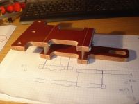
I had put the solution to this problem out, due to it containing many parts to solve just one problem, so I am happy that it is now in the book.
Cheers, Finn Hammer
Finn Hammer, Sun Mar 28 2010, 05:37PM
Had a couple of hours to spare, so turned to Thumpa'
It would be an act of vanity to asume, that the primary coil could be produced completely round. Also, that the assembly that drives the tapping point along it, is centered with enough precision.
In the ordinary coil, this is of no consequence, but this is no ordinary coil.
So some sort of mechanical buffer has to be inserted between the driver and the driven, to keep it from jamming.

Inserted are 2 blades of 0.2mm thick G10. They act as leaf springs, giving the tapping drive stick unrestricted axial movement, within amble reason.
Took 4 hours to design in Solidworks, 3 hours to complete in real life.

I had put the solution to this problem out, due to it containing many parts to solve just one problem, so I am happy that it is now in the book.
Cheers, Finn Hammer
Re: "Thumper"
Finn Hammer, Tue Apr 06 2010, 04:17PM
May there sound a big hooray, and a 'Hats Off', for the automotive industry!
Thumper has 2 DC gear motors. They'r not automotive types, but.....

-they need to be controlled. Forward, reverse and in PWM. Nothing fancy, but still...
In comes the automotive search parameter and Viola!: The mighty VNH3SP30-E.
A full bridge with integrated controll logic, charge pumps, over current protection, diagnostic and whatnot.
Good for 30A @40V too.....
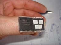
Most pins are power in, gnd and power out, only 3 are for controll:
2 of them determine fwd, rev or brake, the 3rd. takes PWM signal.
This chip mates directly with the AtMega 328 that's going to controll them, via a fiber optic link.
Daniel and Simon are coding till their fingers bleed, to make this remote controll communicate via serial protocol

A bottom frame of rectangular stainless steel pipe was designed and manufactured during easter, it completes the primary mainframe to a point where I can climb it without doing any damage.
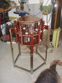
All in all a good easter's worth og build and design.
Cheers, Finn Hammer
Finn Hammer, Tue Apr 06 2010, 04:17PM
May there sound a big hooray, and a 'Hats Off', for the automotive industry!
Thumper has 2 DC gear motors. They'r not automotive types, but.....

-they need to be controlled. Forward, reverse and in PWM. Nothing fancy, but still...
In comes the automotive search parameter and Viola!: The mighty VNH3SP30-E.
A full bridge with integrated controll logic, charge pumps, over current protection, diagnostic and whatnot.
Good for 30A @40V too.....

Most pins are power in, gnd and power out, only 3 are for controll:
2 of them determine fwd, rev or brake, the 3rd. takes PWM signal.
This chip mates directly with the AtMega 328 that's going to controll them, via a fiber optic link.
Daniel and Simon are coding till their fingers bleed, to make this remote controll communicate via serial protocol

A bottom frame of rectangular stainless steel pipe was designed and manufactured during easter, it completes the primary mainframe to a point where I can climb it without doing any damage.

All in all a good easter's worth og build and design.
Cheers, Finn Hammer
Re: "Thumper"
Dr Hankenstein, Wed Apr 07 2010, 03:54AM
Finn,
That's one rockin' design....always something innovative from you! (But then, I wouldn't expect anything less) I really like the pheonolic touch.....now that's money; dude! Awesome that you will be able to re-couple on the fly...I'm sure we are all going to be very jealous indeed. What a research tool you have here.
Thank's for sharing, big dude!
Woo
Re: "Thumper"
Dr. Drone, Thu Apr 08 2010, 04:17AM

Dr. Drone, Thu Apr 08 2010, 04:17AM

Re: "Thumper"
Finn Hammer, Sun Apr 18 2010, 05:11PM
I am the first to admit that building coils can lure the builder into dead ends, where there seems to be no solution to manufacturing challenges, often at the very end of a complicated project. This frequently reduces the master builder to a cursing and nail biting meanace, feared by family, neighbours and passers by.
I was starting to look a lot like that, recently.
Reason for this was, that the day for winding the copper tube into a primary coil was rapidly approaching, and I had absolutely no clue how I was going to lure this thin walled 22mm tube into accepting the proposed diametre of 560mm, without it becoming completely flat.
My coiling buddy and worthy adversary, Daniel Uhrenholt, was by my side in this dire moment, and with his help, the tube was preliminarily reduced to a 580mm diametre coil, as seen below:
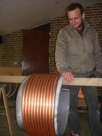
After this was done, an afternoon passed, carefully nudging the coil into the primary supports, and tying them temporarily with Tiewraps:
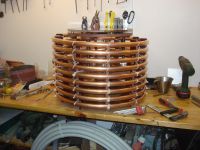
It was now time to drill the holes that secure the primary coil to the supports:
A special drilling jig was fabricated out of a nice block of aluminum, and 2 drill bushings were turned, so that I could drill the holes.
The holes have to be aligned to the center of the support, as well as the center of the tube, so that when the screw is inserted, the tube is in the correct position, and so that there is correct clearance for the tapping point to pass.
Here you can see the jig entering position to drill the first hole, 5mm, to allow the screw head to enter the tube:
Next, the jig in position, showing the drill bushing for the 3.5mm hole at the inner perimetre of the tube, where it is fastned to the support:
Last picture today shows the coil liberated from the first row of Tiewraps, and the coil permanently secured to the former. You can see that it has a screw loose, I dropped one screw in there.
The tapping point is going to pass over these holes, but I can live with that.
Since the motors that position the tapping point and the coupling position are controlled by an embedded microprocessor, we can now get a feature implemented, that needs attention:
When tapping to a different primary frequency, the coupling also changes due to the change in primary coil geometry. This changes the coupling too.
The Microprocessor will be programmed to change the coupling to maintain it's desired value, during tapping the frequency.
A very productive weekend, thanks to Daniel and greetings to you all.
Cheers, Finn Hammer
Finn Hammer, Sun Apr 18 2010, 05:11PM
I am the first to admit that building coils can lure the builder into dead ends, where there seems to be no solution to manufacturing challenges, often at the very end of a complicated project. This frequently reduces the master builder to a cursing and nail biting meanace, feared by family, neighbours and passers by.
I was starting to look a lot like that, recently.
Reason for this was, that the day for winding the copper tube into a primary coil was rapidly approaching, and I had absolutely no clue how I was going to lure this thin walled 22mm tube into accepting the proposed diametre of 560mm, without it becoming completely flat.
My coiling buddy and worthy adversary, Daniel Uhrenholt, was by my side in this dire moment, and with his help, the tube was preliminarily reduced to a 580mm diametre coil, as seen below:

After this was done, an afternoon passed, carefully nudging the coil into the primary supports, and tying them temporarily with Tiewraps:

It was now time to drill the holes that secure the primary coil to the supports:
A special drilling jig was fabricated out of a nice block of aluminum, and 2 drill bushings were turned, so that I could drill the holes.
The holes have to be aligned to the center of the support, as well as the center of the tube, so that when the screw is inserted, the tube is in the correct position, and so that there is correct clearance for the tapping point to pass.

Here you can see the jig entering position to drill the first hole, 5mm, to allow the screw head to enter the tube:

Next, the jig in position, showing the drill bushing for the 3.5mm hole at the inner perimetre of the tube, where it is fastned to the support:

Last picture today shows the coil liberated from the first row of Tiewraps, and the coil permanently secured to the former. You can see that it has a screw loose, I dropped one screw in there.
The tapping point is going to pass over these holes, but I can live with that.

Since the motors that position the tapping point and the coupling position are controlled by an embedded microprocessor, we can now get a feature implemented, that needs attention:
When tapping to a different primary frequency, the coupling also changes due to the change in primary coil geometry. This changes the coupling too.
The Microprocessor will be programmed to change the coupling to maintain it's desired value, during tapping the frequency.
A very productive weekend, thanks to Daniel and greetings to you all.
Cheers, Finn Hammer
Re: "Thumper"
ScotchTapeLord, Sun Apr 18 2010, 07:16PM
Great to see it coming along, but isn't that tap a bit close to the next winding?
ScotchTapeLord, Sun Apr 18 2010, 07:16PM
Great to see it coming along, but isn't that tap a bit close to the next winding?
Re: "Thumper"
Finn Hammer, Sun Apr 18 2010, 07:30PM
If what you refer to as a tap is the aluminum drill jig, then absolutely yes!
But it is a drill jig, not a tapping point.
Here is the tapping point:
It is a novel 'tapper', riding on the inside of the coil on ball bearings, to allow tuning the coil on the fly. See also further up.
Cheers, Finn Hammer
Finn Hammer, Sun Apr 18 2010, 07:30PM
ScotchTapeLord wrote ...
Great to see it coming along, but isn't that tap a bit close to the next winding?
Great to see it coming along, but isn't that tap a bit close to the next winding?
If what you refer to as a tap is the aluminum drill jig, then absolutely yes!
But it is a drill jig, not a tapping point.
Here is the tapping point:

It is a novel 'tapper', riding on the inside of the coil on ball bearings, to allow tuning the coil on the fly. See also further up.
Cheers, Finn Hammer
Re: "Thumper"
ScotchTapeLord, Sun Apr 18 2010, 09:18PM
Ohh... okay! Gosh, that sure looks great...
ScotchTapeLord, Sun Apr 18 2010, 09:18PM
Ohh... okay! Gosh, that sure looks great...
Re: "Thumper"
Linas, Mon Apr 19 2010, 07:02AM
i have question
Predictor can compensate driver delay , but does that delay depend of operating frequency ? Because my driver has constant delay for various frequencies so if i change oscillation frequency, do i need tune predictor again ?
th
Linas, Mon Apr 19 2010, 07:02AM
i have question
Predictor can compensate driver delay , but does that delay depend of operating frequency ? Because my driver has constant delay for various frequencies so if i change oscillation frequency, do i need tune predictor again ?
th
Re: "Thumper"
Finn Hammer, Mon Apr 19 2010, 04:50PM
Linas,
I frankly don´t know, so I hope someone with better circuit theory will chime in here.
Terry Fritz did some calculations, and I seem to recall that he said it was pretty much "spot on" within the frequency shift that could be expected due to streamer loading.
*I* adjust the Predikter to the frequency that the coil is Idling at, and hope it stays good during streamer load.
The field around Thumper is so grand, that even if it is running with just enough voltage in to run, then I get arcs to ground from my toes in sandals! So I have not been able to check with the scope real close.
This will change with the new faraday suit, which will allow me or Daniel to monitor the timing at full output.
I am sorry that this is the best i can doo at the moment.
I love the work you are doing, and wish I could take half as well lit pictures as you do!
Cheers, Finn Hammer
Finn Hammer, Mon Apr 19 2010, 04:50PM
Linas wrote ...
i have question
Predictor can compensate driver delay , but does that delay depend of operating frequency ? Because my driver has constant delay for various frequencies so if i change oscillation frequency, do i need tune predictor again ?
th
i have question
Predictor can compensate driver delay , but does that delay depend of operating frequency ? Because my driver has constant delay for various frequencies so if i change oscillation frequency, do i need tune predictor again ?
th
Linas,
I frankly don´t know, so I hope someone with better circuit theory will chime in here.
Terry Fritz did some calculations, and I seem to recall that he said it was pretty much "spot on" within the frequency shift that could be expected due to streamer loading.
*I* adjust the Predikter to the frequency that the coil is Idling at, and hope it stays good during streamer load.
The field around Thumper is so grand, that even if it is running with just enough voltage in to run, then I get arcs to ground from my toes in sandals! So I have not been able to check with the scope real close.
This will change with the new faraday suit, which will allow me or Daniel to monitor the timing at full output.
I am sorry that this is the best i can doo at the moment.
I love the work you are doing, and wish I could take half as well lit pictures as you do!
Cheers, Finn Hammer
Re: "Thumper"
Finn Hammer, Sun Apr 25 2010, 08:02PM
The Thumper mainframe is coming along nicely:
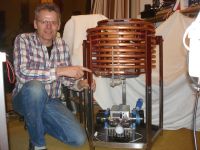
Today, Daniel generously milled out what has become the golden standard of controll gearing for DRSSTC tapping point positioning, since there are identical elements in his Diable Tonnere coil: The pinion and internal gear:
This allowed me to wrap up the Tapping Point for Thumper. It still has to pass the high current test, which will be performed when I receive the cool-amp Conducto Lube silver powder lubricant:

But just to stir your envy, not penis envy this time, but something more powerful, Tapper-envy, Here I give you the preview video of what just might become the future standard of DRSSTC real time tuning:

Cheers, Finn Hammer
Finn Hammer, Sun Apr 25 2010, 08:02PM
The Thumper mainframe is coming along nicely:

Today, Daniel generously milled out what has become the golden standard of controll gearing for DRSSTC tapping point positioning, since there are identical elements in his Diable Tonnere coil: The pinion and internal gear:

This allowed me to wrap up the Tapping Point for Thumper. It still has to pass the high current test, which will be performed when I receive the cool-amp Conducto Lube silver powder lubricant:

But just to stir your envy, not penis envy this time, but something more powerful, Tapper-envy, Here I give you the preview video of what just might become the future standard of DRSSTC real time tuning:

Cheers, Finn Hammer
Re: "Thumper"
Steve Conner, Mon Apr 26 2010, 09:40AM
Whether you need to retune a constant delay depends on how big the change in frequency is. The PLL driver I used in Mjolnir has a constant delay, and I set it once when I built the coil and haven't touched it since. I didn't make any major changes to the system, apart from changing the tank capacitor from 0.05uF to 0.1uF.
Something to bear in mind: Does the switching delay time of your IGBTs depend on frequency? Surely if anything, it depends on current.
Can't wait to see this working Finn! :P
Steve Conner, Mon Apr 26 2010, 09:40AM
Linas wrote ...
i have question
Predictor can compensate driver delay , but does that delay depend of operating frequency ? Because my driver has constant delay for various frequencies so if i change oscillation frequency, do i need tune predictor again ?
th
There are several different Prediktor designs. According to Steve Ward, the one with the inductor (IIRC) has a delay that varies with frequency in the right way to compensate changes in operating frequency. His latest design takes this into account, but I'm not sure if his earlier ones did.i have question
Predictor can compensate driver delay , but does that delay depend of operating frequency ? Because my driver has constant delay for various frequencies so if i change oscillation frequency, do i need tune predictor again ?
th
Whether you need to retune a constant delay depends on how big the change in frequency is. The PLL driver I used in Mjolnir has a constant delay, and I set it once when I built the coil and haven't touched it since. I didn't make any major changes to the system, apart from changing the tank capacitor from 0.05uF to 0.1uF.
Something to bear in mind: Does the switching delay time of your IGBTs depend on frequency? Surely if anything, it depends on current.
Can't wait to see this working Finn! :P
Re: "Thumper"
Finn Hammer, Mon Apr 26 2010, 11:35AM
I am having a hard time waiting myself.
When we get around to it, we (that's Daniel and Myself) plan to arrange a TeslaTune, where all are invited and welcome.
TeslaTune? That's right, you read right:
We are in concord with modernity, here, and Teslathon is an awkward, oldfasioned word, that just don't have the right ring to it, anymore.
When Teslists gather, they discuss and display tuning techniques, and listen to tunes played on coils. Time passes in a jiffy, so why the Painfull, exhausting marathon connotation?
Heard in the ghetto, recently: (Girl asks boy) "Did you attend the Continental TeslaTune last weekend? It was awesome!"
You are all coming....
Cheers, Finn Hammer
Finn Hammer, Mon Apr 26 2010, 11:35AM
Steve McConner wrote ...
Can't wait to see this working Finn! :P
Can't wait to see this working Finn! :P
I am having a hard time waiting myself.
When we get around to it, we (that's Daniel and Myself) plan to arrange a TeslaTune, where all are invited and welcome.
TeslaTune? That's right, you read right:
We are in concord with modernity, here, and Teslathon is an awkward, oldfasioned word, that just don't have the right ring to it, anymore.
When Teslists gather, they discuss and display tuning techniques, and listen to tunes played on coils. Time passes in a jiffy, so why the Painfull, exhausting marathon connotation?
Heard in the ghetto, recently: (Girl asks boy) "Did you attend the Continental TeslaTune last weekend? It was awesome!"
You are all coming....
Cheers, Finn Hammer
Re: "Thumper"
Finn Hammer, Thu May 13 2010, 06:48PM
The capacitor for Thumper was initially just 10 strings of each 10 CD 940C12W1P5K-F caps.
I felt it was time to put them together in something resembling permanence.
After some time with SolidWorks, machining of the parts started. Not so much to confirm that I am a plaxi-hater, but rather because I had the sheets in stock, the combs that hold the caps in position are made from clear PVC:
Here is the basic module, there are 2 of them:
Half finished, I test if it fits into the mainframe:
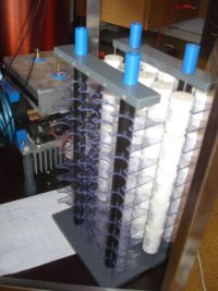
Here the caps have been fitted into the frame:
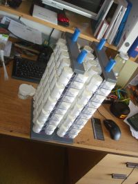
The capacitor on a large DRSSTC is a major component.
How big is yours?
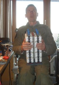
When the busswork on a capacitor is treated with the attention worthy of a Ferrari, it becomes pertinent to question the sanity of the constructor:
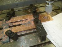
But then, when this buss is integrated with a 5kA rotary contact, the chances of mating with sanity are rapidly decreasing: here the individual parts
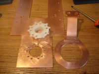
Assembled:
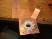
Tested with the cap:
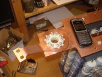
And here the finished article:
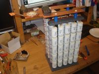
The rotary contact ensures that the inductance of the wiring doesn't change during tapping, and it also provides a hole to pass the wires from the motors and end stops down from above.
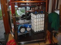
If anybody feels like shouting: "But that contact presents a shorted turn to the primary coil" do it now and let's be done with it!
A video that shows the function of the rotary contact:
Another great step towards the RATDRSSTC has been completed!
Cheers, Finn Hammer
Finn Hammer, Thu May 13 2010, 06:48PM
The capacitor for Thumper was initially just 10 strings of each 10 CD 940C12W1P5K-F caps.
I felt it was time to put them together in something resembling permanence.
After some time with SolidWorks, machining of the parts started. Not so much to confirm that I am a plaxi-hater, but rather because I had the sheets in stock, the combs that hold the caps in position are made from clear PVC:

Here is the basic module, there are 2 of them:

Half finished, I test if it fits into the mainframe:

Here the caps have been fitted into the frame:

The capacitor on a large DRSSTC is a major component.
How big is yours?

When the busswork on a capacitor is treated with the attention worthy of a Ferrari, it becomes pertinent to question the sanity of the constructor:

But then, when this buss is integrated with a 5kA rotary contact, the chances of mating with sanity are rapidly decreasing: here the individual parts

Assembled:

Tested with the cap:

And here the finished article:

The rotary contact ensures that the inductance of the wiring doesn't change during tapping, and it also provides a hole to pass the wires from the motors and end stops down from above.

If anybody feels like shouting: "But that contact presents a shorted turn to the primary coil" do it now and let's be done with it!
A video that shows the function of the rotary contact:

Another great step towards the RATDRSSTC has been completed!
Cheers, Finn Hammer
Re: "Thumper"
Dalus, Thu May 13 2010, 07:03PM
Wow, that MMC is huge compared to the bridge. No chance of blowing a cap
Dalus, Thu May 13 2010, 07:03PM
Wow, that MMC is huge compared to the bridge. No chance of blowing a cap

Re: "Thumper"
tobias, Fri May 14 2010, 12:07AM
Nice piece of machinery you have been using sir! And the right tools for each job! I wish some day I'll have those too for my hobbies!
Very good job! Being sane is aways the boring option! hehehe
tobias, Fri May 14 2010, 12:07AM
Nice piece of machinery you have been using sir! And the right tools for each job! I wish some day I'll have those too for my hobbies!
Very good job! Being sane is aways the boring option! hehehe
Re: "Thumper"
Dalus, Fri May 14 2010, 08:09AM
Hehe you need to built your bridge like mine. It pretty much looks like a V-8 engine. Would be quite suitable for your ferrari. Still have a lot of metalwork to do though
Dalus, Fri May 14 2010, 08:09AM
Hehe you need to built your bridge like mine. It pretty much looks like a V-8 engine. Would be quite suitable for your ferrari. Still have a lot of metalwork to do though

Re: "Thumper"
Mads Barnkob, Fri May 14 2010, 09:39AM
You never seize to amaze me and I will visit you and Daniel this summer :)
Mads Barnkob, Fri May 14 2010, 09:39AM
You never seize to amaze me and I will visit you and Daniel this summer :)
Re: "Thumper"
Daniel Uhrenholt, Fri May 14 2010, 11:21AM
Nice work Finn!
I have to steal the idea of the rotary contact for my coil, when I have time to make the MMC for it:-)
I have to update the Diable Tonnere thread today, as I am almost done with it now… The toroid you saw at the shop earlier today is now done and I just need to get it to my apartment somehow…
Cheers, Daniel
Daniel Uhrenholt, Fri May 14 2010, 11:21AM
Nice work Finn!
I have to steal the idea of the rotary contact for my coil, when I have time to make the MMC for it:-)
I have to update the Diable Tonnere thread today, as I am almost done with it now… The toroid you saw at the shop earlier today is now done and I just need to get it to my apartment somehow…

Cheers, Daniel
Re: "Thumper"
Finn Hammer, Fri May 14 2010, 06:47PM
Some pictures of that V8 engine would be nice. Feel free to post them to this thread, if you like.
Cheers
And about time too! Looking forward to that!
And Daniel, feel welcome to steal, copy and plagiarise as you feel fit. Everybody, I want you to plagiarise!, that's the whole idea with this thread.
Cheers
Finn Hammer, Fri May 14 2010, 06:47PM
Dalus wrote ...
Hehe you need to built your bridge like mine. It pretty much looks like a V-8 engine. Would be quite suitable for your ferrari. Still have a lot of metalwork to do though
Hehe you need to built your bridge like mine. It pretty much looks like a V-8 engine. Would be quite suitable for your ferrari. Still have a lot of metalwork to do though

Some pictures of that V8 engine would be nice. Feel free to post them to this thread, if you like.
Cheers
Mads Barnkob wrote ...
You never seize to amaze me and I will visit you and Daniel this summer :)
You never seize to amaze me and I will visit you and Daniel this summer :)
And about time too! Looking forward to that!
And Daniel, feel welcome to steal, copy and plagiarise as you feel fit. Everybody, I want you to plagiarise!, that's the whole idea with this thread.
Cheers
Re: "Thumper"
Dalus, Fri May 14 2010, 09:26PM
Hope to get most of the metalwork done by Monday. Then it's cutting some teflon by hand for the cap supports.
Dalus, Fri May 14 2010, 09:26PM
Hope to get most of the metalwork done by Monday. Then it's cutting some teflon by hand for the cap supports.
Re: "Thumper"
Daniel Uhrenholt, Sat May 15 2010, 08:11AM
I didn`t see your post Mads.
We can arrange a little Danish Thon this summer:-) Be sure to bring a coil or two, I will find a place where we can make sparks all day long!
Cheers, Daniel
Daniel Uhrenholt, Sat May 15 2010, 08:11AM
I didn`t see your post Mads.
We can arrange a little Danish Thon this summer:-) Be sure to bring a coil or two, I will find a place where we can make sparks all day long!
Cheers, Daniel
Re: "Thumper"
Mads Barnkob, Sun May 16 2010, 09:56AM
Got my VTTC and SSTC3 that lives, the SSTC2 is dead for the moment, a primary flashover killed some windings on the secondary :(
A weekend would be the best for me, all vacation is already booked up :)
Mads Barnkob, Sun May 16 2010, 09:56AM
Daniel Uhrenholt wrote ...
I didn`t see your post Mads.
We can arrange a little Danish Thon this summer:-) Be sure to bring a coil or two, I will find a place where we can make sparks all day long!
Cheers, Daniel
I didn`t see your post Mads.
We can arrange a little Danish Thon this summer:-) Be sure to bring a coil or two, I will find a place where we can make sparks all day long!
Cheers, Daniel
Got my VTTC and SSTC3 that lives, the SSTC2 is dead for the moment, a primary flashover killed some windings on the secondary :(
A weekend would be the best for me, all vacation is already booked up :)
Re: "Thumper"
Dalus, Thu May 20 2010, 07:57AM
Monday was a bit more busy then expected First year at the uni also sucks up time rather fast. So I didn't get the copper busbar done. But I did take a pic of how things look now. Think you can allready guess how the busbar will look from the picture.

Don't know when I'll have time to get working on the copper again. Lots of stuff to do and some problems at home that need my attention.
Dalus, Thu May 20 2010, 07:57AM
Monday was a bit more busy then expected
 First year at the uni also sucks up time rather fast. So I didn't get the copper busbar done. But I did take a pic of how things look now. Think you can allready guess how the busbar will look from the picture.
Don't know when I'll have time to get working on the copper again. Lots of stuff to do and some problems at home that need my attention.
Re: "Thumper"
Finn Hammer, Thu Jun 03 2010, 10:45AM
Generous fillets applied to all, otherwise protruding, corners, are the trademark of a CNC machined product.
But I don't have that, so my fillets are applied, retrospectively, the good *old school* way.
This is how it is done:
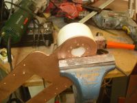
A suitably radiussed backup slug, the descent of the file is effectively controlled.
I want safety, but I don't want to be soldering all night.
When looking at soldering 200 bleeder resistors, a down and dirty solder jig is mandatory.
Shut up, get done with it, and solder!
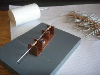
2 x 10M for a 30sec time constant, going easy on the Q
And finally some CAD porn: Huwow, a lot of hours must have gone into that!
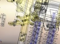
I am about ready to apply Conducto Lube to the mating surfaces of the sliding Pulsed Kiloamp connections, and am modestly proposing first light this first coming Sunday.
Cheers, Finn Hammer
Finn Hammer, Thu Jun 03 2010, 10:45AM
Generous fillets applied to all, otherwise protruding, corners, are the trademark of a CNC machined product.
But I don't have that, so my fillets are applied, retrospectively, the good *old school* way.
This is how it is done:

A suitably radiussed backup slug, the descent of the file is effectively controlled.
I want safety, but I don't want to be soldering all night.
When looking at soldering 200 bleeder resistors, a down and dirty solder jig is mandatory.
Shut up, get done with it, and solder!

2 x 10M for a 30sec time constant, going easy on the Q

And finally some CAD porn: Huwow, a lot of hours must have gone into that!

I am about ready to apply Conducto Lube to the mating surfaces of the sliding Pulsed Kiloamp connections, and am modestly proposing first light this first coming Sunday.
Cheers, Finn Hammer
Re: "Thumper"
Coronafix, Thu Jun 03 2010, 12:23PM
Beautiful work Finn, especially the radiusss.
Coronafix, Thu Jun 03 2010, 12:23PM
Beautiful work Finn, especially the radiusss.
Re: "Thumper"
Finn Hammer, Thu Jun 03 2010, 08:40PM
Thanks, Coronafx
And now the circuit is closed, just waiting to get pulsed by the motor

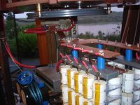

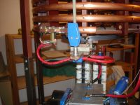

Cheers, Finn Hammer
Finn Hammer, Thu Jun 03 2010, 08:40PM
Coronafix wrote ...
Beautiful work Finn, especially the radiusss.
Beautiful work Finn, especially the radiusss.
Thanks, Coronafx
And now the circuit is closed, just waiting to get pulsed by the motor


Cheers, Finn Hammer
Re: "Thumper"
Dalus, Thu Jun 03 2010, 08:52PM
Have fun powering this beast up. And keep us posted.
Dalus, Thu Jun 03 2010, 08:52PM
Have fun powering this beast up. And keep us posted.
Re: "Thumper"
Coronafix, Thu Jun 03 2010, 10:59PM
You'll probably want to keep changing toploads on it so you can keep tuning it. :)
Coronafix, Thu Jun 03 2010, 10:59PM
You'll probably want to keep changing toploads on it so you can keep tuning it. :)
Re: "Thumper"
Finn Hammer, Fri Jun 04 2010, 05:09AM
Actually, I doubt the topload is going to be changed, unless I can muster enough gumption to make a larger one.
The reason that I made the cap configurable is, that I want to be able to search for a possible sweet spot, where the L/C ratio is different. Like, better sparklength/pri_current ratio
Wow, now so close to the moment where i watch the scope, while sweeping past the sweet spot, recording it for you all to see.
Cheers, Finn Hammer
Finn Hammer, Fri Jun 04 2010, 05:09AM
Coronafix wrote ...
You'll probably want to keep changing toploads on it so you can keep tuning it. :)
You'll probably want to keep changing toploads on it so you can keep tuning it. :)
Actually, I doubt the topload is going to be changed, unless I can muster enough gumption to make a larger one.

The reason that I made the cap configurable is, that I want to be able to search for a possible sweet spot, where the L/C ratio is different. Like, better sparklength/pri_current ratio
Wow, now so close to the moment where i watch the scope, while sweeping past the sweet spot, recording it for you all to see.
Cheers, Finn Hammer
Re: "Thumper"
Daniel Uhrenholt, Fri Jun 04 2010, 06:05AM
Nice work Finn,
I can`t wait until Sunday, where we will see if all of this hard work works as we planned:-) Yesterday I soldered the last PCB for the motor controller, so this afternoon I will write the last code for it...
See you Sunday!
Cheers, Daniel
Daniel Uhrenholt, Fri Jun 04 2010, 06:05AM
Nice work Finn,
I can`t wait until Sunday, where we will see if all of this hard work works as we planned:-) Yesterday I soldered the last PCB for the motor controller, so this afternoon I will write the last code for it...
See you Sunday!
Cheers, Daniel
Re: "Thumper"
Finn Hammer, Sun Jun 06 2010, 09:09PM
We had first light tonight, and tested the tapping point to 2kA where it was able to tap smoothly and without letting out any smoke.
The following video was recorded.

What you hear and see is the current ringdown on the scope, and the streamer developing. We start with one half turn too low, and tune up towards a good tuning point, where notches appear, then we shorten the on-time untill it coincides with the first notch.
Notice how the current decreases as the streamer increases, and that the streamer don't get any shorter, when we shorten the on-time in the end.
The sweet spot is hard to locate, as it appears very sharply within less than 5 centimeters on the coil.
Cheers, Finn and Daniel
Finn Hammer, Sun Jun 06 2010, 09:09PM
We had first light tonight, and tested the tapping point to 2kA where it was able to tap smoothly and without letting out any smoke.
The following video was recorded.

What you hear and see is the current ringdown on the scope, and the streamer developing. We start with one half turn too low, and tune up towards a good tuning point, where notches appear, then we shorten the on-time untill it coincides with the first notch.
Notice how the current decreases as the streamer increases, and that the streamer don't get any shorter, when we shorten the on-time in the end.
The sweet spot is hard to locate, as it appears very sharply within less than 5 centimeters on the coil.
Cheers, Finn and Daniel
Re: "Thumper"
hvguy, Mon Jun 07 2010, 10:30PM
Wow Finn, congratulations on pulling off an incredible design. It's already interesting to hear your tuning point is so narrow, I can't wait to see it make huge arcs! Have you played with the coupling yet? Great work....
hvguy, Mon Jun 07 2010, 10:30PM
Wow Finn, congratulations on pulling off an incredible design. It's already interesting to hear your tuning point is so narrow, I can't wait to see it make huge arcs! Have you played with the coupling yet? Great work....
Re: "Thumper"
Finn Hammer, Tue Jun 08 2010, 08:17AM
Thanks, Aron
Haven't played with coupling to any great extent, but enough to visualize, that it doesn't have a very dramatic effect. I have not understood Antonio's writings

well enough to memorise them, but I feel that the holy gail lies buryed in there, and I built this machine to be able to investigate that.
I don't know if this sounds familiar but, the day of final light was occupied with tasks like *making those motor controllers work* and we also did not know if the tapping point was going to be up to it. So we decided to put the ultimate restraint on ourselves: Go for recording that video, period.
It does not appear as obvious to many others, but *I* think it is the most important Tesla Coil Video recorded in a long time.
Tuning of the DRSSTC may have been discussed in great detail in the past, but then I have missed it. A paper that pins it down, and supports the claims with easy to understand videos is what is needed by the average Joe's, like myself. The gap between Antonio and Average needs to be filled.
Cheers, Finn Hammer
This will not happen in short order, as I am moving to another town. I doubt I will have time for any extensive testing in the next couple of months
Finn Hammer, Tue Jun 08 2010, 08:17AM
hvguy wrote ...
Wow Finn, congratulations on pulling off an incredible design. It's already interesting to hear your tuning point is so narrow, I can't wait to see it make huge arcs! Have you played with the coupling yet? Great work....
Wow Finn, congratulations on pulling off an incredible design. It's already interesting to hear your tuning point is so narrow, I can't wait to see it make huge arcs! Have you played with the coupling yet? Great work....
Thanks, Aron
Haven't played with coupling to any great extent, but enough to visualize, that it doesn't have a very dramatic effect. I have not understood Antonio's writings

well enough to memorise them, but I feel that the holy gail lies buryed in there, and I built this machine to be able to investigate that.
I don't know if this sounds familiar but, the day of final light was occupied with tasks like *making those motor controllers work* and we also did not know if the tapping point was going to be up to it. So we decided to put the ultimate restraint on ourselves: Go for recording that video, period.
It does not appear as obvious to many others, but *I* think it is the most important Tesla Coil Video recorded in a long time.
Tuning of the DRSSTC may have been discussed in great detail in the past, but then I have missed it. A paper that pins it down, and supports the claims with easy to understand videos is what is needed by the average Joe's, like myself. The gap between Antonio and Average needs to be filled.
Cheers, Finn Hammer
This will not happen in short order, as I am moving to another town. I doubt I will have time for any extensive testing in the next couple of months
Re: "Thumper"
hvguy, Thu Jun 10 2010, 04:43AM
Yes, working out all the little details of the system, especially when there are numerious PCBs/uCs involved can be time consuming, I'm glad to see you got some video.
Having all this information presented in video form will certainly be a great asset to future coilers seeking to understand the nuances of Tesla Coil operation. I agree with you, this design could very well be one of the most relevant ever. I'm surprised to see a small response here, at least the TCML has provided better feedback. I must say, with all you've done to progress this hobby with this design a book could very well be in order.
I hope your up coming move involves a larger shop space and maybe an open field to run this coil in

Re: "Thumper"
Steve Conner, Thu Jun 10 2010, 09:14AM

I don't think there is any consensus on DRSSTC tuning yet. I have one way of doing it that only works with my PLL drivers. Steve Ward has two other ways of doing it, one for small coils, another for large coils, that work with his feedback driver. I stopped doing research, and my stuff is pretty outdated now, so if you're looking for a consensus, do what the other Steve says.
Much of the discussion in the past was really argument about whose method was best. I believe that my method ended up best for small coils, and Steve Ward's for large coils. He demonstrated real improvements in power output and efficiency by tuning his big coils for a notch, but in a small coil, not enough energy is transferred by the time of the first notch.
The tuning point you found in the video corresponds to Steve's "Large coil" method.
Steve Conner, Thu Jun 10 2010, 09:14AM
hvguy wrote ...
I'm surprised to see a small response here
We're all still in shock. I'm surprised to see a small response here

I don't think there is any consensus on DRSSTC tuning yet. I have one way of doing it that only works with my PLL drivers. Steve Ward has two other ways of doing it, one for small coils, another for large coils, that work with his feedback driver. I stopped doing research, and my stuff is pretty outdated now, so if you're looking for a consensus, do what the other Steve says.

Much of the discussion in the past was really argument about whose method was best. I believe that my method ended up best for small coils, and Steve Ward's for large coils. He demonstrated real improvements in power output and efficiency by tuning his big coils for a notch, but in a small coil, not enough energy is transferred by the time of the first notch.
The tuning point you found in the video corresponds to Steve's "Large coil" method.
Re: "Thumper"
Dalus, Thu Jun 10 2010, 11:34AM
Wow, very nice. This coil is great for demo's on the principals of operation of a coil. You did a great job
Dalus, Thu Jun 10 2010, 11:34AM
Wow, very nice. This coil is great for demo's on the principals of operation of a coil. You did a great job

Re: "Thumper"
vasil, Thu Jun 10 2010, 05:56PM
Very good work, I read every new post here and on TCML and I am happy to see how the coils of the future are made today...
My DRSSTC experiences ended a few years ago, so no much feedback from me too. And you build at large scale.....I will never be able to replicate this on small coils..sad but true.
Re: "Thumper"
Daniel Uhrenholt, Fri Jun 11 2010, 07:27AM
Finn and I are both moving to another town this summer, and we are looking for some kind of lab in the area:-) It would be great to have all of our equipment in one place, as there is not enough space in our apartments to do any experiments at all... I hope that we find a place that is big enough to have Diable Tonnere standing for a longer period of time to do experiments and documentation on tuning. And also some kind of yard where we can do experiments on Thumper, but the problem is to find a place where there is not so many neighbors to worry about...
Cheers, Daniel
Daniel Uhrenholt, Fri Jun 11 2010, 07:27AM
hvguy wrote ...
I hope your up coming move involves a larger shop space and maybe an open field to run this coil in
I hope your up coming move involves a larger shop space and maybe an open field to run this coil in

Finn and I are both moving to another town this summer, and we are looking for some kind of lab in the area:-) It would be great to have all of our equipment in one place, as there is not enough space in our apartments to do any experiments at all... I hope that we find a place that is big enough to have Diable Tonnere standing for a longer period of time to do experiments and documentation on tuning. And also some kind of yard where we can do experiments on Thumper, but the problem is to find a place where there is not so many neighbors to worry about...
Cheers, Daniel
Re: "Thumper"
Nicko, Fri Jun 11 2010, 03:32PM
Just wanted to say that this is so very impressive - big coils worry me a bit (my own limits), but good engineering is always a thing of beauty.
Cheers
Nicko, Fri Jun 11 2010, 03:32PM
Just wanted to say that this is so very impressive - big coils worry me a bit (my own limits), but good engineering is always a thing of beauty.
Cheers
Re: "Thumper"
Chris Russell, Thu Jun 17 2010, 01:51AM
Thumper is now featured on the front page of 4hv.org, as well as Hackaday. Excellent work, Finn. You're truly an inspiration.
Chris Russell, Thu Jun 17 2010, 01:51AM
Thumper is now featured on the front page of 4hv.org, as well as Hackaday. Excellent work, Finn. You're truly an inspiration.
Re: "Thumper"
Finn Hammer, Thu Jun 17 2010, 06:01AM
Thanks, Chris, for your kind words.
In all honesty, I am the one who feels honoured.
Cheers, Finn Hammer
Finn Hammer, Thu Jun 17 2010, 06:01AM
Chris Russell wrote ...
Thumper is now featured on the front page of 4hv.org, as well as Hackaday. Excellent work, Finn. You're truly an inspiration.
Thumper is now featured on the front page of 4hv.org, as well as Hackaday. Excellent work, Finn. You're truly an inspiration.
Thanks, Chris, for your kind words.
In all honesty, I am the one who feels honoured.
Cheers, Finn Hammer
Re: "Thumper"
GhostNull, Fri Jun 25 2010, 05:54AM
Great Work Finn Hammer!
You're an inspiration to anyone wanting to build a tesla coil!
GhostNull, Fri Jun 25 2010, 05:54AM
Great Work Finn Hammer!
You're an inspiration to anyone wanting to build a tesla coil!
Re: "Thumper"
Patrick, Sat Jun 26 2010, 07:14AM
i refuse to be defeated by the hard drive crap-out, therefore i will complement Finn and Daniel once again.
the copper work on your bridge is MASTERFUL in both form and execution, i also did follow your links Finn, and yes i found your motor pics, and your gear, bearing, and rotating plate design looks sound.
Nice work!
Re: "Thumper"
Bennem, Sat Jun 26 2010, 09:36AM
Oh well, some folks have always complained that i repeat myself,
but now in have an excuse here....hehe
Hi Finn,
i've so enjoyed this thread from its begining,
your work is a masterpiece as per usual.
and the info you'll get will be of great interest to us
non mathematical folks who would like to understand the
practical relationship between spark length,coupling and tunning,
and all done in real time!!
So congrats to you Finn and Daniel for some excellent work!!
All the best,
Mel.
Re: "Thumper"
Dr. Drone, Tue Jun 29 2010, 12:24AM

Dr. Drone, Tue Jun 29 2010, 12:24AM

Re: "Thumper"
Coronafix, Tue Jun 29 2010, 01:12AM
Finn has always been famous Dr Spark!! Way back with his first adjustable tap TC. Not sure if he still has that page up anymore.
Well done Finn, I believe that you have recently advanced DRSSTCs to a new level of Brilliant!!
Coronafix, Tue Jun 29 2010, 01:12AM
Finn has always been famous Dr Spark!! Way back with his first adjustable tap TC. Not sure if he still has that page up anymore.
Well done Finn, I believe that you have recently advanced DRSSTCs to a new level of Brilliant!!
Re: "Thumper"
UbuntuNinja, Sun Jul 04 2010, 03:43AM
Nice work this is awesome. This thing gives Steve Wards DRSSTC2 some competition! I have two questions. First of all, about the toroid, were the rings already circular when you got them or did you have to bend/shape them and where did you get them from? Also regarding the bridge, where did you get the 40N60 bricks from? I thought those things were classified as "obsolete" by Fairchild and so they are not manufactured anymore.
Re: "Thumper"
Finn Hammer, Sun Jul 04 2010, 12:49PM

But note that Thumper uses CM600 silicon.
Cheers, Finn Hammer
Finn Hammer, Sun Jul 04 2010, 12:49PM
UbuntuNinja wrote ...
Nice work this is awesome. This thing gives Steve Wards DRSSTC2 some competition! I have two questions. First of all, about the toroid, were the rings already circular when you got them or did you have to bend/shape them and where did you get them from?
They were straight, as in full 18 feet lengths of pipe. We had to bend them ourselves.Nice work this is awesome. This thing gives Steve Wards DRSSTC2 some competition! I have two questions. First of all, about the toroid, were the rings already circular when you got them or did you have to bend/shape them and where did you get them from?
UbuntuNinja wrote ...
Also regarding the bridge, where did you get the 40N60 bricks from? I thought those things were classified as "obsolete" by Fairchild and so they are not manufactured anymore.
You would be very envious, if you saw my stash of parts, aquired over a 10 year period. Period Also regarding the bridge, where did you get the 40N60 bricks from? I thought those things were classified as "obsolete" by Fairchild and so they are not manufactured anymore.

But note that Thumper uses CM600 silicon.
Cheers, Finn Hammer
Re: "Thumper"
UbuntuNinja, Mon Jul 05 2010, 06:03AM
Do you have a picture of the process you used to bend the pipes into shape? How did you manage to keep them so perfectly round and what pipe size did you use?
Thanks,
UbuntuNinja
UbuntuNinja, Mon Jul 05 2010, 06:03AM
Finn Hammer wrote ...
You would be very envious, if you saw my stash of parts, aquired over a 10 year period. Period
But note that Thumper uses CM600 silicon.
Cheers, Finn Hammer
I thought it said on the first page that the bridge was 40N60s.You would be very envious, if you saw my stash of parts, aquired over a 10 year period. Period

But note that Thumper uses CM600 silicon.
Cheers, Finn Hammer
Do you have a picture of the process you used to bend the pipes into shape? How did you manage to keep them so perfectly round and what pipe size did you use?
Thanks,
UbuntuNinja
Re: "Thumper"
Finn Hammer, Mon Jul 05 2010, 06:39AM
This is a standard plumber job, and I have no pictures. Using a proper pipe, and the necessary skill, a roller bender normally results in near perfectly round rings.
Cheers, Finn Hammer
Finn Hammer, Mon Jul 05 2010, 06:39AM
UbuntuNinja wrote ...
I thought it said on the first page that the bridge was 40N60s.
If does. But that was only to develop the Predikter, a not insignificant subassembly of the coil.I thought it said on the first page that the bridge was 40N60s.
UbuntuNinja wrote ...
Do you have a picture of the process you used to bend the pipes into shape? How did you manage to keep them so perfectly round and what pipe size did you use?
Thanks,
UbuntuNinja
Do you have a picture of the process you used to bend the pipes into shape? How did you manage to keep them so perfectly round and what pipe size did you use?
Thanks,
UbuntuNinja
This is a standard plumber job, and I have no pictures. Using a proper pipe, and the necessary skill, a roller bender normally results in near perfectly round rings.
Cheers, Finn Hammer
Re: "Thumper"
UbuntuNinja, Wed Jul 07 2010, 07:39PM
UbuntuNinja, Wed Jul 07 2010, 07:39PM
Finn Hammer wrote ...
This is a sandard plumber job, and I have no pictures. Using a proper pipe, and the necessary skill, a roller bender normally results in near perfectly round rings.
Cheers, Finn Hammer
All right, thanks. What type of pipe do you recommend?This is a sandard plumber job, and I have no pictures. Using a proper pipe, and the necessary skill, a roller bender normally results in near perfectly round rings.
Cheers, Finn Hammer
Re: "Thumper"
Finn Hammer, Thu Jul 08 2010, 03:45PM
There are a lot of "if's" to the choice of pipe.
Diametre: *around* an inch, to one and a half.....
Wall thickness: thick enough to avoid dents, not so thick as to get too heavy.
Hardness: Soft enough to bend well, not so soft that it bends too easily when you move it around.
Weldability is a must.
Allu grade: Different systems in Europe and US
Hard question to answer...
Cheers, Finn Hammer
Re: "Thumper"
Dr. Mario, Tue Aug 03 2010, 09:04PM
Nice tesla coil project! However, I like your Prediktor primary coil setup - nice to see that your tesla coil have a brain keen enough to find such a nice sweet spot for suchj a big spark.
Would want to do that one too! ^____^
( About ten-year gathered parts, I must agree with that one, the envy of the basement tweakers. :| )
Re: "Thumper"
Reaching, Thu Aug 12 2010, 08:54AM
Hey Finn.
I read this thread with enthusiasm ^^ first of all i wondered what this predikter thing would do and why it has become so popular within a few weeks. so i had to try it on my own. first of all i simulated some things and calculated a bit.. that was boring ^^ But i wanted to simplify the design and get rid of this symmetrical power supply.
yesterday i build my predikter version into my drsstc9 and was surprised. it worked after a few minutes of fiddling, and the signals went better and better.. the perfomance increase is frightning^^ dont know if my coil was not in tune or something but after i build in that predikter, it worked fantastic!
attached is my simple predikter version ^^

Re: "Thumper"
Finn Hammer, Fri Aug 13 2010, 05:08AM
Reaching,
Thanks for sharing.
Obviously, I have to say:" Of course it works better with the Predikter" but still it is nice to hear confirming reports.
Particularly from the experts, like yourself
Cheers, Finn Hammer
Finn Hammer, Fri Aug 13 2010, 05:08AM
Reaching,
Thanks for sharing.
Obviously, I have to say:" Of course it works better with the Predikter" but still it is nice to hear confirming reports.
Particularly from the experts, like yourself

Cheers, Finn Hammer
Re: "Thumper"
Dr. H., Sat Aug 14 2010, 01:21PM
Good day and great work guys !
Reaching - what is the function of L3 ?
Cheers
Dr. H., Sat Aug 14 2010, 01:21PM
Good day and great work guys !

Reaching - what is the function of L3 ?
Cheers
Re: "Thumper"
Reaching, Sat Aug 14 2010, 02:23PM
L3 is build close to L2 and is picking up some noise from it, around 5mV which is in phase with the incoming feedback signal. so i have a small signal sinus at the noninverting input of the comparator which is slightly positive at the positive halfwave and slightly negative at the negative halfwave of the sine. dont know if that makes much sense, but i wanted to be shure that no noise straiing into the comp or the feedback ct(through ground loops etc) can trigger the comparator back within a positive switching transition.
for sure i could add a resistor instead of L3 but then the signal at the non inverting input of the comparator is sligthly positive at all time, and then the comparator doesnt put out a nice 50/50 squarewave. or i could have put the pin on gnd,, but then i would be afraid of oscillations of the comparator. i think everything from a 3turn coil to a resistor with 0,1ohm or something would be suitable..
Re: "Thumper"
Finn Hammer, Sun Aug 15 2010, 07:48AM
Reaching,
Brilliant thoughts led to L3, I like it!
I just biassed ground leg -8mV(ish) and be done with it. Perhaps at the first transition, where input from CT is low, it leads to measurable assymmetry in output squarewave, but at 4kA+, with like 6V in from CT, hardly a concern.
Nevertheless, a nice, elegant addition to the predikter.
Cheers, Finn Hammer
Re: "Thumper"
Finn Hammer, Fri Oct 22 2010, 07:41PM
Seing a feature described with words, or a picture sometimes, just doesn't cut it. A video is the thing.
Here is a video of Daniel and myself, erecting the secondary of Thumper.
This is to show the convenience of having a hinged platform at the bottom of the secondary.
Cheers, Finn Hammer
Finn Hammer, Fri Oct 22 2010, 07:41PM
Seing a feature described with words, or a picture sometimes, just doesn't cut it. A video is the thing.
Here is a video of Daniel and myself, erecting the secondary of Thumper.

This is to show the convenience of having a hinged platform at the bottom of the secondary.
Cheers, Finn Hammer
Re: "Thumper"
colin heath, Sun Nov 14 2010, 08:24PM
Finn fantastic work as always and the attention to detail is outstanding.
I have managed to steer clear of coils for around 7 months now but seeing this has really got some creative juices flowing!
Once I get my Hillclimb car finished then a rather large coil is in the making I feel:-D
Re: "Thumper"
Tesla Fan, Mon Nov 15 2010, 10:19AM
I would just like to add my compliments, this is one of the best man-made “constructions†(of any kind) i have ever seen! A truly amazing project, your engineering is above professional level!
Tesla Fan, Mon Nov 15 2010, 10:19AM
I would just like to add my compliments, this is one of the best man-made “constructions†(of any kind) i have ever seen! A truly amazing project, your engineering is above professional level!
Re: "Thumper"
Finn Hammer, Sat Dec 18 2010, 01:20PM
Thumper may not care much, but *I* never got at ease with the gate drive transformers I had to resort to, in order to get her running in time.
Recently, I have been working on new gate driver boards, and thus this little report.
I wanted to use an all N-channel mosfet half bridge, and to do this with opto isolated input, I had to sequence the mosfets with a half bridge driver chip. Many nice ones to chose from, I selected the LM5104, due to it's inherent suitedness. It is a one input driver with programmable deadtime.
the present schematic looks like this:

As you see, the gates of the stack needed to be calmed down some more, to get nice waveforms all way round.
Here is a late prototype set up for celebrity photography:
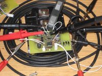
"A smd prototype soon aquires the appearance of a sea urchin when equipped with test points at key nodes."
At this stage, I dumped the zener clamps on the board supply, and opted for full linear regulation, which lead to this present prototype:
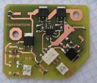
Not fully populated, it essentially does what the previous versions do, put out nice waveforms..
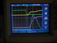
Yellow trace is gate voltage at top halfbridge mosfet, Q1, 8V/div
Green trace is voltage at gate of bottom halfbridge mosfet, Q2, 8V/div.
Cyan trace is current into gate of CM600, 2A/div.
Magenta trace is volage on Gate of CM600, 10V/div.
You will see that Q1 is in essence performing the double task of switch and gate resistor, most of the current into CM600 gate being delivered while it's gate is still in the miller plateau.
It turns the CM600 on in less than 500nS, without ringing or overshooting the gate voltage, and without hesitating at the miller plateau.
In my opinion, that is the ultimate gate drive.
Whether this is right will become the topic of my next installment.
With this, I wish you all a merry christmas.
Cheers, Finn Hammer
Finn Hammer, Sat Dec 18 2010, 01:20PM
Thumper may not care much, but *I* never got at ease with the gate drive transformers I had to resort to, in order to get her running in time.
Recently, I have been working on new gate driver boards, and thus this little report.
I wanted to use an all N-channel mosfet half bridge, and to do this with opto isolated input, I had to sequence the mosfets with a half bridge driver chip. Many nice ones to chose from, I selected the LM5104, due to it's inherent suitedness. It is a one input driver with programmable deadtime.
the present schematic looks like this:

As you see, the gates of the stack needed to be calmed down some more, to get nice waveforms all way round.
Here is a late prototype set up for celebrity photography:

"A smd prototype soon aquires the appearance of a sea urchin when equipped with test points at key nodes."
At this stage, I dumped the zener clamps on the board supply, and opted for full linear regulation, which lead to this present prototype:

Not fully populated, it essentially does what the previous versions do, put out nice waveforms..

Yellow trace is gate voltage at top halfbridge mosfet, Q1, 8V/div
Green trace is voltage at gate of bottom halfbridge mosfet, Q2, 8V/div.
Cyan trace is current into gate of CM600, 2A/div.
Magenta trace is volage on Gate of CM600, 10V/div.
You will see that Q1 is in essence performing the double task of switch and gate resistor, most of the current into CM600 gate being delivered while it's gate is still in the miller plateau.
It turns the CM600 on in less than 500nS, without ringing or overshooting the gate voltage, and without hesitating at the miller plateau.
In my opinion, that is the ultimate gate drive.
Whether this is right will become the topic of my next installment.
With this, I wish you all a merry christmas.
Cheers, Finn Hammer
Re: "Thumper"
Dr. Drone, Sat Dec 18 2010, 05:23PM

Dr. Drone, Sat Dec 18 2010, 05:23PM

Re: "Thumper"
Dr Hankenstein, Sat Dec 18 2010, 07:03PM
Nice job, Finn. Your mind just never stops. I must compliment you on your persistence and innovation; always a cut above the rest!
Dr Hankenstein, Sat Dec 18 2010, 07:03PM
Nice job, Finn. Your mind just never stops. I must compliment you on your persistence and innovation; always a cut above the rest!
Re: "Thumper"
Finn Hammer, Sun Dec 19 2010, 07:11PM
The only parts that didn't make it in time were the rectifier diodes for the input bridge, I guess not much can go wrong there, so the presumption is that it woikd :
:
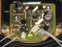
What else then, than to initiate "big etch evening", where I also had time to do that burst interuptor board for Daniel which you see in the middle.
I use photoresist stock, print artwork on laser transparencies, have a UV lightbox, develop shamelessly with drain cleaner in water, etch with one third each of hydrocloric acid 30%, peroxide 35% and water. Works for me.
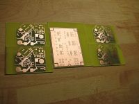
Wow, this is good winter hobby.
Cheers, Finn Hammer
Finn Hammer, Sun Dec 19 2010, 07:11PM
The only parts that didn't make it in time were the rectifier diodes for the input bridge, I guess not much can go wrong there, so the presumption is that it woikd
 :
:
What else then, than to initiate "big etch evening", where I also had time to do that burst interuptor board for Daniel which you see in the middle.
I use photoresist stock, print artwork on laser transparencies, have a UV lightbox, develop shamelessly with drain cleaner in water, etch with one third each of hydrocloric acid 30%, peroxide 35% and water. Works for me.

Wow, this is good winter hobby.
Cheers, Finn Hammer
Re: "Thumper"
Daniel Uhrenholt, Mon Dec 20 2010, 06:26AM
Looking good Finn.
You have always been productive this time of year, but there isn't much else to do because of the weather...:)
I see that you made the interrupter PCB for me, so you have to drop by some day for coffee.
Cheers, Daniel
Daniel Uhrenholt, Mon Dec 20 2010, 06:26AM
Looking good Finn.
You have always been productive this time of year, but there isn't much else to do because of the weather...:)
I see that you made the interrupter PCB for me, so you have to drop by some day for coffee.
Cheers, Daniel
Re: "Thumper"
Steve Ward, Thu Dec 23 2010, 05:44PM
The gate drivers i designed for CM600s showed <100nS rise time on the gate... its of course bogus because you arent measuring the voltage at the gate, rather you are measuring the voltage at the driver and there is plenty of module inductance and resistance between it and the gate electrode. So unless you measured the collector current change, i wouldnt claim any switching speed based on what the external gate electrodes show.
Steve Ward, Thu Dec 23 2010, 05:44PM
It turns the CM600 on in less than 500nS, without ringing or overshooting the gate voltage, and without hesitating at the miller plateau.
The gate drivers i designed for CM600s showed <100nS rise time on the gate... its of course bogus because you arent measuring the voltage at the gate, rather you are measuring the voltage at the driver and there is plenty of module inductance and resistance between it and the gate electrode. So unless you measured the collector current change, i wouldnt claim any switching speed based on what the external gate electrodes show.
Print this page