
Class E Circuit
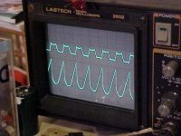
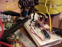
ragnar, Fri Apr 07 2006, 07:24AMMy lil crappy class-E circuit.. coming soon =)
That waveform is overdamped with a capital 'F' - I've just found my 'smaller capacitors' box, so I'll post more pics tonight when I replace my blown components. Tee hee.
Re: Class E Circuit
Desmogod, Fri Apr 07 2006, 07:44AM
What does class E plasma look like in a plasma globe?
Desmogod, Fri Apr 07 2006, 07:44AM
What does class E plasma look like in a plasma globe?
Re: Class E Circuit
WaveRider, Fri Apr 07 2006, 08:27AM
Hi BP..
Are you operating below resonance?
Here's my latest result..
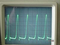
This was done with a simple variation of the Armstrong oscillator. (Single-sided cousin of Royer.. )
)
WaveRider, Fri Apr 07 2006, 08:27AM
Hi BP..
Are you operating below resonance?
Here's my latest result..

This was done with a simple variation of the Armstrong oscillator. (Single-sided cousin of Royer..
 )
)Re: Class E Circuit
Dr. Shark, Fri Apr 07 2006, 11:45AM
Hey, you are getting exactly the same crap that I get in my class E circuit! Exponential ramp which crashes down as the FET switches, instead a a nice, smooth damped oscillation. I have not worked on my circuit lately because first I was out of parts and then I got ill, but I'll try some more class E-ing soon.
Its a shame that Richie Burnett, the father of the Class E SSTC is not on this board!
Re: Class E Circuit
Steve Conner, Fri Apr 07 2006, 12:01PM
I know, I've tried to get him to join :P He explains how to tune a Class-E SSTC on his site anyway:

You adjust the primary turns, coupling, and shunt capacitor by trial and error until the waveform looks right, then turn up the power a bit and adjust it all again (since the corona loading is non-linear) Repeat until you're running at full power. It's tempting to use a ham radio antenna tuner to make the adjustments easier. I would use an air-spaced variable capacitor out of an old radio as the shunt cap at least.
I say BP needs looser coupling and a smaller shunt capacitor.
Steve Conner, Fri Apr 07 2006, 12:01PM
I know, I've tried to get him to join :P He explains how to tune a Class-E SSTC on his site anyway:

You adjust the primary turns, coupling, and shunt capacitor by trial and error until the waveform looks right, then turn up the power a bit and adjust it all again (since the corona loading is non-linear) Repeat until you're running at full power. It's tempting to use a ham radio antenna tuner to make the adjustments easier. I would use an air-spaced variable capacitor out of an old radio as the shunt cap at least.
I say BP needs looser coupling and a smaller shunt capacitor.
Re: Class E Circuit
WaveRider, Fri Apr 07 2006, 12:30PM
Judging by the snippet of your primary in the photo, I'd agree with Steve. I used only 4 turns in my primary...you have lots!
By doing the Spice simulations, I was able to establish that a coupling coefficient of about k=0.18 and a 180pF shunt cap (given by my modeling of the coupled resonator-primary system) yields the desired waveforms at 4.7MHz with my choice of transistor. Your situation will vary, based on resonant frequency, transistor and choice of DC voltage supply.
In short, I did trial and error using Spice to find the right capacitor value, and found the sims to be pretty much spot-on when I cobbled together the working model...
Good luck!
Re: Class E Circuit
Dr. Shark, Sat Apr 08 2006, 02:41PM
I know, this is what I would do when I was at least somewhere near the desired oscillatory waveform. One could make a small change and see if it gets better or worse. But in this situation, where the waveform is completely off, it is really hard to tell if some change makes it better or worse. I even emailed Richie about it, but his reply did not help much.
Btw, according to you can get rid of the shunt cap completely if your FET can stand the voltage spike, and I tried that (removed it completely) without any benefit. Back to the shop...
Edit:
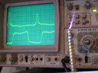
getting classy here...
now if I just knew how to get the drain voltage to rise right after the FET switches off, and not only when it is just about to turn on again, I'd be a happy guy.
Another peculiar thing that is definitely worth menioning: I am driving the coil at exactly half the resonant frequency. The calculated f_0 is 3.6MHz, the driver runs at 1.8MHz. I do not know if this is possible at all, but it seems to produce sparks
Dr. Shark, Sat Apr 08 2006, 02:41PM
Steve Conner wrote ...
You adjust the primary turns, coupling, and shunt capacitor by trial and error until the waveform looks right, then turn up the power a bit and adjust it all again (since the corona loading is non-linear) Repeat until you're running at full power. It's tempting to use a ham radio antenna tuner to make the adjustments easier. I would use an air-spaced variable capacitor out of an old radio as the shunt cap at least.
You adjust the primary turns, coupling, and shunt capacitor by trial and error until the waveform looks right, then turn up the power a bit and adjust it all again (since the corona loading is non-linear) Repeat until you're running at full power. It's tempting to use a ham radio antenna tuner to make the adjustments easier. I would use an air-spaced variable capacitor out of an old radio as the shunt cap at least.
I know, this is what I would do when I was at least somewhere near the desired oscillatory waveform. One could make a small change and see if it gets better or worse. But in this situation, where the waveform is completely off, it is really hard to tell if some change makes it better or worse. I even emailed Richie about it, but his reply did not help much.
Btw, according to
 you can get rid of the shunt cap completely if your FET can stand the voltage spike, and I tried that (removed it completely) without any benefit. Back to the shop...
 Edit:

getting classy here...
now if I just knew how to get the drain voltage to rise right after the FET switches off, and not only when it is just about to turn on again, I'd be a happy guy.
Another peculiar thing that is definitely worth menioning: I am driving the coil at exactly half the resonant frequency. The calculated f_0 is 3.6MHz, the driver runs at 1.8MHz. I do not know if this is possible at all, but it seems to produce sparks

Re: Class E Circuit
Steve Conner, Sat Apr 08 2006, 04:22PM
I just got this from Richie-
I think what he's saying is: You'll find it a hell of a lot easier to tune for a proper drain voltage waveform if you use a fixed oscillator to drive the system rather than a self-resonant driver.
The arrows on his tuning guide show which way the waveform will move when you adjust that given circuit constant. The object is to get the bit that the arrows come from to land at zero volts just as the FET switches on.
Steve Conner, Sat Apr 08 2006, 04:22PM
I just got this from Richie-
Richie Burnett wrote ...
I took a look on 4HV and saw the thread you told me about. I think the
reason why those people are having trouble getting the correct drain
waveform might be because they are trying to use feedback to make the
system
oscillate at the TC's own resonant frequency. You can forward quote
this
Email on the 4HV list if you think it will help discussions there.
A pure Class E amplifier requires a net inductive load at the drain of
the
MOSFET. It is this lagging load current that actually drives the drain
voltage back down towards zero before the MOSFET is commanded to turn
back
on. If the load current doesn't have the required lagging component
the
drain capacitance wont get discharged quick enough and the drain
voltage
wont swing back down to zero in time for the device turning back on.
Therefore you either need to drive the Tesla Resonator at a frequency
somewhat higher than its resonant frequency, _OR_ use a matching
network
that provides an excess of inductive impedance to the MOSFET. Then the
drain will see the required inductive component in the load impedance
and
you can tune it for efficient Class E operation.
There is a Class E amplifier tuning guide here:

Cds is the total drain-source shunt capacitance across the MOSFET. Ls
and
Cs are the components of the series resonant components of the load
impedance presented to the MOSFET's drain. Zbase is the resistive
component
of the load impedance presented to the MOSFET's drain.
There are some pictures of my 8MHz Class E TC in that temp folder also.
I can't see myself ever subscribing to any more Tesla Mailing lists due
to
other comittments, but it is always interesting to see what others are
doing.
I took a look on 4HV and saw the thread you told me about. I think the
reason why those people are having trouble getting the correct drain
waveform might be because they are trying to use feedback to make the
system
oscillate at the TC's own resonant frequency. You can forward quote
this
Email on the 4HV list if you think it will help discussions there.
A pure Class E amplifier requires a net inductive load at the drain of
the
MOSFET. It is this lagging load current that actually drives the drain
voltage back down towards zero before the MOSFET is commanded to turn
back
on. If the load current doesn't have the required lagging component
the
drain capacitance wont get discharged quick enough and the drain
voltage
wont swing back down to zero in time for the device turning back on.
Therefore you either need to drive the Tesla Resonator at a frequency
somewhat higher than its resonant frequency, _OR_ use a matching
network
that provides an excess of inductive impedance to the MOSFET. Then the
drain will see the required inductive component in the load impedance
and
you can tune it for efficient Class E operation.
There is a Class E amplifier tuning guide here:

Cds is the total drain-source shunt capacitance across the MOSFET. Ls
and
Cs are the components of the series resonant components of the load
impedance presented to the MOSFET's drain. Zbase is the resistive
component
of the load impedance presented to the MOSFET's drain.
There are some pictures of my 8MHz Class E TC in that temp folder also.
I can't see myself ever subscribing to any more Tesla Mailing lists due
to
other comittments, but it is always interesting to see what others are
doing.
I think what he's saying is: You'll find it a hell of a lot easier to tune for a proper drain voltage waveform if you use a fixed oscillator to drive the system rather than a self-resonant driver.
The arrows on his tuning guide show which way the waveform will move when you adjust that given circuit constant. The object is to get the bit that the arrows come from to land at zero volts just as the FET switches on.
Re: Class E Circuit
Dr. Shark, Sat Apr 08 2006, 05:39PM
Hey, thanks for getting some expert opinions for us here, but I think I am getting there anyway:
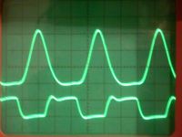
this looks very much like the ZVS part of class E operation is happening as it should, now I need to fine-tune for ZCS. Before I do that, however, I suppose I should swap in a TC secondary that fits my resonant frequency. Since I lost most of the harmonics I had with my weird waveforms before, I am getting no more sparks. Oh, btw, the problem I had before was rather simple: The gate was not pulled to 0V quick enough and my dutycycle was about 90%. So I had to put in a small GDT to pull it negative, now it works nicely.
Dr. Shark, Sat Apr 08 2006, 05:39PM
Hey, thanks for getting some expert opinions for us here, but I think I am getting there anyway:

this looks very much like the ZVS part of class E operation is happening as it should, now I need to fine-tune for ZCS. Before I do that, however, I suppose I should swap in a TC secondary that fits my resonant frequency. Since I lost most of the harmonics I had with my weird waveforms before, I am getting no more sparks. Oh, btw, the problem I had before was rather simple: The gate was not pulled to 0V quick enough and my dutycycle was about 90%. So I had to put in a small GDT to pull it negative, now it works nicely.
Re: Class E Circuit
ragnar, Sun Apr 09 2006, 03:55AM
I'm reducing the primary to a few turns and lowering the coupling by raising the secondary a little. What's delaying me at the moment is making a few PCBs for all this. My breadboard is highly inadequate - it seems I only need to wave my hand past and it all works, and I get waveforms akin to the underdamped one you see in Richie Burnett's tuning guide.
I'll also heatsink mr MOSFET and try 'real' input voltages. For now, everything was running from a 12V lead acid cell.
ragnar, Sun Apr 09 2006, 03:55AM
wrote ...
Hi BP..
Are you operating below resonance?
I'm running at least 30kHz above resonance at ~720kHz. I think I should creep a little closer to fRes though.Hi BP..
Are you operating below resonance?
I'm reducing the primary to a few turns and lowering the coupling by raising the secondary a little. What's delaying me at the moment is making a few PCBs for all this. My breadboard is highly inadequate - it seems I only need to wave my hand past and it all works, and I get waveforms akin to the underdamped one you see in Richie Burnett's tuning guide.
I'll also heatsink mr MOSFET and try 'real' input voltages. For now, everything was running from a 12V lead acid cell.
Re: Class E Circuit
Dr. Shark, Sun Apr 09 2006, 12:42PM
Hehe, I am also kind of cheating on the PCB part, this is what I am using:

It does what it should, but it is getting really croweded since I am adding components all the time. Also the layout is done by hand, not ideal for opertation at 4MHz...
BTW, how do you mangage to keep your semiconductors cool at 12V in? I was able to get a fan cooled heatsink cooking in seconds at that voltage, before the zero switching started to work
Dr. Shark, Sun Apr 09 2006, 12:42PM
Hehe, I am also kind of cheating on the PCB part, this is what I am using:

It does what it should, but it is getting really croweded since I am adding components all the time. Also the layout is done by hand, not ideal for opertation at 4MHz...
BTW, how do you mangage to keep your semiconductors cool at 12V in? I was able to get a fan cooled heatsink cooking in seconds at that voltage, before the zero switching started to work

Re: Class E Circuit
ragnar, Tue Apr 11 2006, 06:05PM
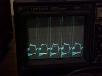
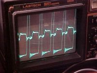
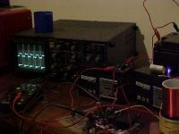
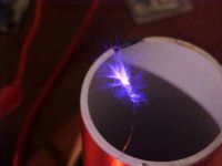
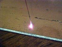
It is done.
I regret I don't have any impedance matching between driver/primary. He runs very nicely with a 4.75nF shunt capacitor and some tweaking.
The turn-on/turn-off times for the MOSFET are unideal (IRFP460 has too large an input capacitance, I feel), and the UCCs are struggling, but thats OK for now - I have found some power supply MOSFETs to salvage for later
I'll now say I'm officially addicted to the class-E amplifier. =)
It's a nice feeling to know that I have to get it wrong four times to blow up a fullbridge' worth of MOSFETs... hehe
ragnar, Tue Apr 11 2006, 06:05PM
It is done.
I regret I don't have any impedance matching between driver/primary. He runs very nicely with a 4.75nF shunt capacitor and some tweaking.
The turn-on/turn-off times for the MOSFET are unideal (IRFP460 has too large an input capacitance, I feel), and the UCCs are struggling, but thats OK for now - I have found some power supply MOSFETs to salvage for later

I'll now say I'm officially addicted to the class-E amplifier. =)
It's a nice feeling to know that I have to get it wrong four times to blow up a fullbridge' worth of MOSFETs... hehe


Re: Class E Circuit
Dr. Shark, Wed Apr 12 2006, 11:25AM
Nice! You won the contest, the price for the first working Class E TC on 4HV is yours! I am falling back more and more, I have massive trouble with my osscilator section, and it does not help that I need to get lots of work done before I ...[go off topic too much?]
Now, what I'd like to know is, are you sure you are in ZCS? It is not visible from the scope shots, in fact the ringing on the drain suggestst that you are not. What you want the drain to do is to return smoothly to zero, not shoot down abruptly.
Re: Class E Circuit
ragnar, Wed Apr 12 2006, 11:34AM
lol, cheers... there was a contest?
Waverider won it first, and he actually knows what he's doing. I'm no RF engineer.
I'm probably not even ZVSing or ZCSing, I don't have the best selection of potential shunt capacitors to use, so I'm mixing and matching with old messes desoldered from the dead circuit boards under my bed.
I did just spot a 2SK539 from a dead power supply board, which I'm dying to try out... Unless I'm reading my scope wrong (likely), the spikes are 7 x Vin... so this will give me some headroom, and I'd better get my 10:1 probes working, hehehe
2SK539 is 900V, 3A, 1.4-1.9nF input capacitance. I'll keep you posted on the results.
Thanks for the feedback Joe, with the exception of you and the two doctors (Steve and Waverider), everyone seems to just lurk atm..
Re: Class E Circuit
Steve Conner, Wed Apr 12 2006, 12:03PM
Hi Joe,
Yes, I think BP has gone off tune in the opposite direction to you, his circuit has too high a resonant frequency and not enough damping, so the voltage returns to zero too early and comes slamming down instead of landing gently. I would try cranking the power to get a bigger spark that loads the circuit more heavily. Or tightening the coupling and increasing the shunt cap somewhat.
It's still pretty good though as he is actually soft switching

Re: Class E Circuit
Desmogod, Wed Apr 12 2006, 12:35PM
When it is actually stable and running correctly, are you going to audio modulate it and tie it in with your previous experiments with plasma speakers?
Desmogod, Wed Apr 12 2006, 12:35PM
When it is actually stable and running correctly, are you going to audio modulate it and tie it in with your previous experiments with plasma speakers?
Re: Class E Circuit
ragnar, Wed Apr 12 2006, 04:01PM
No audio modulation with this baby until I can get the discharge totally silent to begin with. Nobody likes a speaker that hisses
And with class E... errr, I think frequency shifting is my only choice... even then it might be nasty. Linear- and pulse-width- modulation seem out of the question.. unless I can desolder and resolder my shunt capacitors as fast as the audio. :P
ragnar, Wed Apr 12 2006, 04:01PM
No audio modulation with this baby until I can get the discharge totally silent to begin with. Nobody likes a speaker that hisses

And with class E... errr, I think frequency shifting is my only choice... even then it might be nasty. Linear- and pulse-width- modulation seem out of the question.. unless I can desolder and resolder my shunt capacitors as fast as the audio. :P
Re: Class E Circuit
Desmogod, Thu Apr 13 2006, 09:20AM
If you scope out richies site (Which I'm sure you have) He achieves it by modulating the voltage into the final stage of the amp. Apparently, it's a bit of an iffy proposition to actually modulate the frequency because class E is such a narrow band.
His words not mine :P
Just an idea though.
Re: Class E Circuit
ragnar, Fri Apr 14 2006, 02:20AM
By pulse-width modulation, yes, he affects the RF output by giving the gatedrivers/mosfets shorter pulses for less output, however with class-E, the shunt capacitor is critical at a certain value, which is why if you increase the input power or affect the loading you need to retune.
I put it to the test at 60V, smoothed with 10,000uF... beautiful results! 3" brushy discharge... but it exploded sometime afterwards; I was too much of a wuss to put my scope across the D/S, but I calculate it would be ringing up to 400V. What was tuned nicely at 36V will be horribly tuned at 60V.
The great thing was the MOSFET just went "Pffft." - none of this spattering and carbon blasting whilst I struggle with foot-on-wall to remove the plug. So I can destroy four class-E output stages as compared with blasting four MOSFETs to hell in a fullbridge simultaneously.
I consider this a 75% saving in silicon. =)
I'm wary of increasing the coupling too much more; I need to lasercut that former to separate primary from secondary.
5.75MHz, here we come =)
Re: Class E Circuit
Marko, Mon Jul 03 2006, 01:06AM
Something to revive an old thread (rather than opening new one) =)
I just recently played with a mini class E coil.
I used PLL (firstly it was direct feedback to UCC, but I didn't want to push the button. Instead of adding NE555 I just added an 4046 wich gives much more possibilities)
Circuit works either from an antenna or base current feedback.
At first it was nothing impressive, some 1cm streamer forom 16V input.
Frequency is 1,4Mhz,
When I added an resonant capacitor and better decoupling to the power supply, the coil went nuts.
Operating at 16V I could draw an 3,5cm long arc from the topload, even without best ZCS tune. I have only cheap digital meters and I couldn't measure current reliably. It looked like it was about 1A.
I can use VCO pot to finetune ZCS if necessary. I got it almost perfect but mosfet still heats up a small heatsink to 50-60 degrees (and stays about there) after about a minute :/ (but without good ZCS it would boil water at that point).
Mosfet is IRFP450, a 1337 one (been in many SSTC's already and never died).
One important thing with such designs is to put an additional big filter cap physically close to primary LC.
This eliminates power supply inductance (behaves as a voltage source) and only inductance of primary and it's leads 'matters'.
Adding this cap really pumped the output, especially since I was using aligator clips on power supply
Unfortunately my camera's battery charger died and I have o recent pics of sparks
But here is an old one, while coil was jet simple direct-feedback single mosfet SSTC.
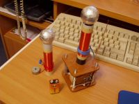
Marko, Mon Jul 03 2006, 01:06AM
Something to revive an old thread (rather than opening new one) =)
I just recently played with a mini class E coil.
I used PLL (firstly it was direct feedback to UCC, but I didn't want to push the button. Instead of adding NE555 I just added an 4046 wich gives much more possibilities)
Circuit works either from an antenna or base current feedback.
At first it was nothing impressive, some 1cm streamer forom 16V input.
Frequency is 1,4Mhz,
When I added an resonant capacitor and better decoupling to the power supply, the coil went nuts.
Operating at 16V I could draw an 3,5cm long arc from the topload, even without best ZCS tune. I have only cheap digital meters and I couldn't measure current reliably. It looked like it was about 1A.
I can use VCO pot to finetune ZCS if necessary. I got it almost perfect but mosfet still heats up a small heatsink to 50-60 degrees (and stays about there) after about a minute :/ (but without good ZCS it would boil water at that point).
Mosfet is IRFP450, a 1337 one (been in many SSTC's already and never died).
One important thing with such designs is to put an additional big filter cap physically close to primary LC.
This eliminates power supply inductance (behaves as a voltage source) and only inductance of primary and it's leads 'matters'.
Adding this cap really pumped the output, especially since I was using aligator clips on power supply

Unfortunately my camera's battery charger died and I have o recent pics of sparks

But here is an old one, while coil was jet simple direct-feedback single mosfet SSTC.

Re: Class E Circuit
ragnar, Mon Jul 03 2006, 01:22AM
Looks absolutely gorgeous, Firkragg =)
I like the case and stand, etc. I never get round to doing that.
What does the shunt capacitor hit up to after each pulse?
-Matt
ragnar, Mon Jul 03 2006, 01:22AM
Looks absolutely gorgeous, Firkragg =)
I like the case and stand, etc. I never get round to doing that.
What does the shunt capacitor hit up to after each pulse?
-Matt
Re: Class E Circuit
Marko, Mon Jul 03 2006, 01:35AM
Cap sees 50 volts max.
I guess your problem is way too much inductance on primary. You need to lower it to limit initial spike (and I guess you should have some better impedance match that way).
I have 50/16 = 3,125Vin peak on mosfet and it closely matches richie burnett's 3.3Vin approximatin.
Later i'm considering putting a small ZVS based power supply into the coil to produce some higher voltages for even scarier sparks. (I want it to completely run from some 12 - 15V supply).
4046 IC is a bit pain there as he wants a stable supply, maybe I'l need a low-dropout regulator there.
Single UCC I have there is even more power hungry.
Gate resistor is 2 ohms and waveform is pretty sharp and nice at 1,5Mhz.
It draws more than half an amp of current and can easily burn a 7812 even on a big heatsink.
If increasing gate resistor fails I'l have to either power it directly from supply or use an switching regulator there...
PS. omg, are you really running that mosfet without any heatsink? Mine would get stinking hot that way after few seconds...
Marko, Mon Jul 03 2006, 01:35AM
Cap sees 50 volts max.
I guess your problem is way too much inductance on primary. You need to lower it to limit initial spike (and I guess you should have some better impedance match that way).
I have 50/16 = 3,125Vin peak on mosfet and it closely matches richie burnett's 3.3Vin approximatin.
Later i'm considering putting a small ZVS based power supply into the coil to produce some higher voltages for even scarier sparks. (I want it to completely run from some 12 - 15V supply).
4046 IC is a bit pain there as he wants a stable supply, maybe I'l need a low-dropout regulator there.
Single UCC I have there is even more power hungry.
Gate resistor is 2 ohms and waveform is pretty sharp and nice at 1,5Mhz.
It draws more than half an amp of current and can easily burn a 7812 even on a big heatsink.
If increasing gate resistor fails I'l have to either power it directly from supply
 or use an switching regulator there...
 PS. omg, are you really running that mosfet without any heatsink? Mine would get stinking hot that way after few seconds...
Re: Class E Circuit
Steve Ward, Mon Jul 03 2006, 02:02AM
Kinda going way back but Joe said:

I think the most i got was about 6" sparks. It was kinda cool i guess because it could make the sword like streamers, but its not quite a fun as full-bridge drivers :P. If you build them right, they dont explode . I sold the coil to some teacher and hes been using it ever since. Heard back to him several months after he bought it and it was still pumping out little sparks like it should, so its pretty reliable. But, it will never handle very high powers like an H-bridge. Each topology has its own place, and class E is perfect for small, high frequency (and efficiency) converters.
Steve Ward, Mon Jul 03 2006, 02:02AM
Kinda going way back but Joe said:
Nice! You won the contest, the price for the first working Class E TC on 4HV is yours!

I think the most i got was about 6" sparks. It was kinda cool i guess because it could make the sword like streamers, but its not quite a fun as full-bridge drivers :P. If you build them right, they dont explode
 . I sold the coil to some teacher and hes been using it ever since. Heard back to him several months after he bought it and it was still pumping out little sparks like it should, so its pretty reliable. But, it will never handle very high powers like an H-bridge. Each topology has its own place, and class E is perfect for small, high frequency (and efficiency) converters.
Re: Class E Circuit
Marko, Mon Jul 03 2006, 11:34AM
I stuck an 7805-based charger into my camera and it works now. I had to drill the connector to make it fit :p
Pics of whole mess:
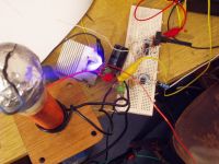
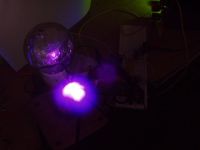
The arc drawn is 33mm long. Looks a bit fuzzy in CW, probably I need much shorter exposure.
Coil is running at 16V, with maybe a little more than 1 amp. (circle some 20 watts).
Spark looks pretty good for given input power.
I had to overcouple coil and detune a bit for this, so mosfet could get pretty hot after >10 minutes (but I never managed to kill it yet :/).
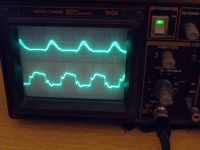
I also took a pic of my waveform, when best tuned. Sinewavy thing is DS voltage, and this garbled looking waveform is gate voltage :p (I couldn't help it much).
In best tune and lower coupling spark is few mm smaller but mosfet gets that heatsink up to maybe 50-60 degrees and could run forever like that.
Anyway i'm still not sure if I really have maximum efficiency there.
Marko, Mon Jul 03 2006, 11:34AM
I stuck an 7805-based charger into my camera and it works now. I had to drill the connector to make it fit :p
Pics of whole mess:


The arc drawn is 33mm long. Looks a bit fuzzy in CW, probably I need much shorter exposure.
Coil is running at 16V, with maybe a little more than 1 amp. (circle some 20 watts).
Spark looks pretty good for given input power.
I had to overcouple coil and detune a bit for this, so mosfet could get pretty hot after >10 minutes (but I never managed to kill it yet :/).
I also took a pic of my waveform, when best tuned. Sinewavy thing is DS voltage, and this garbled looking waveform is gate voltage :p (I couldn't help it much).
In best tune and lower coupling spark is few mm smaller but mosfet gets that heatsink up to maybe 50-60 degrees and could run forever like that.
Anyway i'm still not sure if I really have maximum efficiency there.
Print this page