Single stage halfbride coil gun V2
Lekky1, Sat Mar 28 2009, 11:08AMHello all!
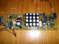
I have completed the basic electronics for my latest coil gun.
Basic specs are the same as my previous version.
Based on what I learnt from the previous design, I've used three IGBT's instead of two & am using current sharing resistors in the "emitter" circuit. Also using a ferrite bead over the gate lead to attempt to minimize ringing.
Unfortunately I don't have a DSO to see if the bead is effective.
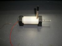
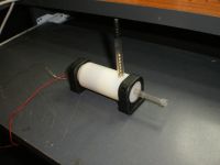
I have made an injector solenoid to load the ball bearings into the coil.
An opto switch will trigger the main coil.
All timing is done by a Picaxe 14M micro.
I've added an LCD display for voltage & pulse value readings.
Coil fires as its supposed to, but I haven't wound final coil to mount on injector solenoid yet.
More details later on.
Pics attached below.


Re: Single stage halfbride coil gun V2
Download, Sat Mar 28 2009, 12:01PM
Looks good.
Does it fire yet?
Download, Sat Mar 28 2009, 12:01PM
Looks good.
Does it fire yet?
Re: Single stage halfbride coil gun V2
101111, Sat Mar 28 2009, 12:40PM
That is one neat coil gun!
101111, Sat Mar 28 2009, 12:40PM
That is one neat coil gun!
Re: Single stage halfbride coil gun V2
Lekky1, Sat Mar 28 2009, 06:45PM
I have tested the PC board without the injector solenoid & optical sensors. It fires.
Have yet to set the injector solenoid & PC board up together.
Hoping to get all together in next couple of weeks.
I've arranged to borrow a friends speed trap when all is done.
Will post more info as I progress.
Re: Single stage halfbride coil gun V2
Lekky1, Sat May 02 2009, 01:48AM
Well, back again!
I have finished preliminary testing of my setup.
Initial coil was wound on a plastic pen casing that was machined to fit.
The inner diameter was just the right size for a BB & was clear for the opto sensors to detect the projectile, but I couldn't get the injector solenoid to work reliably.
I have since made a new coil using brass tubing, slotted to reduce eddy current losses.
Injector functions reliably now. The brass tube has a slightly larger ID, so allows for some misalignment of the BB as it enters.
I should mention that the injector is only used to load the BB. It provides very little pre-acceleration.
Coil is 2cm long & uses approx 230 turns of 0.8mm wire.
Best velocity I can get so far is 116 FPS. This is with a pulse length of 880uS.
Recharge ready for another shot is 3 seconds (Approx.)
When I am finally finished with the BB version, I will try a cylindrical projectile.
I'd like to mention that I am using a commercially available chronograph for speed measuring.
This device is made for use with "Airsoft" guns, is reasonably priced & works well.
After I've finished modifying, I'll study up on the math involved & try to calculate efficiency.
A search on the net regarding BB weight gave .32 grams (5 grain), so will use this weight for a start.
I will post more pics later (camera flat....Doh!)
Next coil will use 1mm wire & slightly less turns......just to try!
Cheers!
Re: Single stage halfbride coil gun V2
TheMerovingian, Fri May 08 2009, 10:45PM
halfbridge coilguns with controlled pulsetime can deliver much of a punch and efficiency. Probably the best topology in terms of performance (rapid current fall) and efficiency (energy recovery), the drawback is cost and space requirements (x2-x2.5 for both) and the careful design (or you will fry tons of expensive IGBT's or Mosfets).
My 3 halfbridge stage rifle got up to 10% efficiency in the latter 2 stages but i will probably never repeat the experience since i'm moving on smaller, more compact systems that uses classical Resistor-Diode damping.
Good work
Re: Single stage halfbride coil gun V2
Lekky1, Sat May 09 2009, 12:48PM
Thank you Merovingian.
I have some questions for the forum members regarding diagonal halfbridge topology.
I'm using an IGBT with an antiparallel diode included in the package (FGL60N100BNTD)
My limited understanding of the purpose of the diode is to prevent damage (latchup?) if the voltage exceeds the collector/emitter reverse breakdown limit.
If using halfbridge topology, can igbt's be used without these antiparallel diodes?
My understanding of the halfbridge sytem is that the back emf is absorbed by the capacitor bank & the voltage across the collector/emitter shouldn't be able to go reverse bias.
The reason I ask is I have a dozen HGTG27N120BN devices that don't have antiparallel diodes incorporated into the package & I'd like to use them. Adding extra antiparallel diodes is inconvenient & wasteful if they are not necessary.
The datasheet says these devices have an emitter-collector breakdown voltage of 15 volts.
Can they be used with single sided topology & a diode connected across the coil (reverse biased) quenching the back emf from the coil at switch off?
If igbt's weren't so expensive, I would use them & find out the hard way!
Cheers!
Print this page