
Synchronous rotary spark gap motor help.
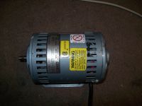
Arcstarter, Tue Mar 10 2009, 05:47PMI got a rotary vane pump a year or two back, and i took the pump part off, to use the motor as a rsg.
Now i want to make a synchronous rotary spark gap with it. I know that you can make an induction motor synchronous by grinding 2 flats in the rotor (i have a 3450rpm motor). The problem is that i have no sophisticated tools and nothing to measure weight or size with. A caliper would be great though.
The motor model number is 1521-107B-G288X.
 It is 1/10 HP, and 3450 RPM with 60hz.
 The tools i have are very basic. Angle grinder, jigsaw, drill. I have sandpaper and a belt sander, and access to a bench grinder.
I basically want to know how i should make the flats. How 'deep' they should be is basically all that i need to know.
Re: Synchronous rotary spark gap motor help.
Herr Zapp, Tue Mar 10 2009, 11:49PM
Arcstarter -
Six seconds searching the web yielded:

Regards,
Herr Zapp
Herr Zapp, Tue Mar 10 2009, 11:49PM
Arcstarter -
Six seconds searching the web yielded:

Regards,
Herr Zapp
Re: Synchronous rotary spark gap motor help.
Timo, Wed Mar 11 2009, 12:41AM
Hi Arcstarter
I will try to help you out by adding some pics showing my SRSG in a disassembled condition. I build it using a motor taken from a laundry / tumble dryer. It was used to power its fan. Maybe it’s something like 1/4 hp, but I don’t know. Now 1500 RPM (50 Hz). The motor turns the wooden disk (diameter 20 cm) easily and never looses synchronisation. It takes about one second to spin up, than all of a sudden the noise generated changes and the motor "locks" to the line frequency. However, it is always possible to slow the disk by touching it with your hand (carefully!) to ad some additional torch.
I noted that the heating of the coils increased a little, and can get uncomfortable to touch if the motor is left running for hours spinning the disk. But a 30min run is no problem at all.
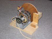
The rotor: As you see it has 4 flats (of course, 1500RPM!)
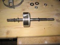
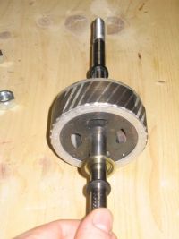
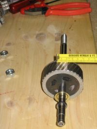
All the Parts:
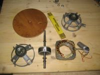
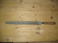
And, finally, a picture of the large number of tools required:
Timo, Wed Mar 11 2009, 12:41AM
Hi Arcstarter
I will try to help you out by adding some pics showing my SRSG in a disassembled condition. I build it using a motor taken from a laundry / tumble dryer. It was used to power its fan. Maybe it’s something like 1/4 hp, but I don’t know. Now 1500 RPM (50 Hz). The motor turns the wooden disk (diameter 20 cm) easily and never looses synchronisation. It takes about one second to spin up, than all of a sudden the noise generated changes and the motor "locks" to the line frequency. However, it is always possible to slow the disk by touching it with your hand (carefully!) to ad some additional torch.
I noted that the heating of the coils increased a little, and can get uncomfortable to touch if the motor is left running for hours spinning the disk. But a 30min run is no problem at all.

The rotor: As you see it has 4 flats (of course, 1500RPM!)


All the Parts:

And, finally, a picture of the large number of tools required:

Re: Synchronous rotary spark gap motor help.
Arcstarter, Wed Mar 11 2009, 01:30AM
@ Herr Zapp:
I actually visited that site. I suppose i am not remembering what i read. I basically want to know how much i should take off. From what i read previously on that site, it states that some of the 'shorts' in the rotor should be taken out. I just need to know how much would be necessary for my motor.
@ Timo:
Thanks alot! That sure does help. I do have a file, but not a rasp >.<. I am sure i can find something abrasive enough though, i could either use the angle grinder, or maybe even my hands (seriously, my calluses are very rough!!)
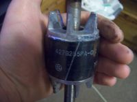
UPDATE: I just noticed, there are two places in the rotor where the color changes (it is grey, when the majority is an iron color). You can see it in the photo on the first post, it was right in the middle of the rotor. It is the last or second to last picture. Should i avoid putting a flat in that part? It would make really no sense to have to, seeing as it looks to be a discontinuity already :P.
Re: Synchronous rotary spark gap motor help.
Herr Zapp, Wed Mar 11 2009, 03:40AM
Arcstarter -
Go back to the evolve site, and take a second look at the procedure that's presented. The instructions are pretty explicit.
There are no "standard" dimensions for the rotor flats; every different motor type and model will have its own unique flat dimensions, based on the motor's rotor and stator dimensions and winding configuration.
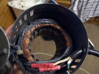
The critical dimension for the rotor flats is the width. Examine your stator assembly, and determine the distance between the "dead" poles. You will want the width of your rotor flats to match the distance between the dead poles on your stator.
If at all possible, find someone with a milling machine and have the flats milled precisely, rather then try to use a file, belt sander, etc. Any machine shop could do this simple machining in 15 - 20 minutes.
The flats CAN be created at home via crude methods, but the rotor balance will never be as satisfactory as on a rotor that has been precisely machined. Because of its higher speed (3600 RPM vs 1800 RPM), your motor will be particularly sensitive to unbalance caused by makeshift machining.
If you don't make the flats large enough, the motor won't achieve synchronism with the AC line when loaded with the RSG disk. If you take off too much material, the motor will run very hot, and still may not have enough torque to synch up.
In any case, after modification the motor will have less torque (= less horsepower) than it originally did. Try to minimize the mass of the RSG wheel and electrodes, while maintaining adequate strength to prevent self-destruction due to centrifugal force.
Regards,
Herr Zapp
Re: Synchronous rotary spark gap motor help.
GeordieBoy, Wed Mar 11 2009, 01:41PM
Timo, that motor is just like the one I used for my first Synchronous RSG. It also came from a clothes dryer and had the same mounting cradle and clips that let you rotate the motor in the cradle. Very important for finding the best firing angle of the spark gap.
I'd say that the amount of material you took off with the hand file is just about right or maybe slightly on the cautious side. A good way to test the salient pole synchronous motors locking ability is to mount the RSG disc and electrodes, spin it up to speed and check it locks. Then slowly decrease the supply voltage to the motor using a variac. You want to be able to get well below the worst case low mains voltage before the motor starts to pole slip (accompanied by that strange "weeeoooouuuw... weeeoooouuuw,,, weeeoooouuuw..." noise!) If the motor pole slips with only a slight reduction in mains voltage, or with slight mechanical loading you need to take off more metal to increase the synchronous locking torque.
The important thing is that if you take off too little metal the motor will only barely lock synchronously with the line. Then when you fire up your high power tesla coil the extra current draw from the line will might make the motor loose synchronicity or will at least shift the firing phase significantly. On the other side, taking off too much metal will cause the motor to run hot because you are increasing the air gap in the magnetic path. For a marginally rated motor it can also reduce the low-speed torque making the motor unable to actually get a large rotary disc up to synchronous speed!
-Richie,
Re: Synchronous rotary spark gap motor help.
Arcstarter, Wed Mar 11 2009, 09:35PM
I have now ground some flats now, but it is still not sync i dont think. When i slow it down enough, i can hear the sound change just like i expected, but this means nothing. I put a dot on the shaft with a sharpie, and put it near a regular 60hz light (the only source of light). I could not even see the dot, no matter where i looked. also, the is a hole from side to side on the shaft, and no matter how i looked through it i could see through it, but with some blur.
Update: Now i tried under a florescent light, and it was no better.
Arcstarter, Wed Mar 11 2009, 09:35PM
I have now ground some flats now, but it is still not sync i dont think. When i slow it down enough, i can hear the sound change just like i expected, but this means nothing. I put a dot on the shaft with a sharpie, and put it near a regular 60hz light (the only source of light). I could not even see the dot, no matter where i looked. also, the is a hole from side to side on the shaft, and no matter how i looked through it i could see through it, but with some blur.


Update: Now i tried under a florescent light, and it was no better.
Re: Synchronous rotary spark gap motor help.
Timo, Thu Mar 12 2009, 01:22AM
Richie, that’s funny. The same motors all across Europe. Btw, I actually tried its ability to lock to the mains frequency exactly as you said. I had to disassemble the motor twice, because I filed down to little in the first try. Now the motor locks at about 180V input with the disk installed and stays locked until the voltage is lowered significantly .
To avoid problems with an unbalanced rotor, I filed as flat and strait as possible (no curvature) and measured the width of the flats (pic 4 in my previous post). Same width gives roughly the same mass. Trivial statement, at least easier than filing straight. But, however, it is a lot less critical with a motor that 1) runs slower, 2) is bigger (12mm shaft, tough bearing), and 3) has a rotor that is heavy compared to the material you need to file away. After all, I think that my wooden disk is a lot worse balanced that the rotor
@ Arcstarter: Maybe your motor runs synchronous already. I was never able to see any sign of synchronous rotation with light bulbs or florescent light tubes. To check for proper operation I used a bright LED driven by a short puls (~ 100-500us) coming from a monoflop (monostable multivibrator? translation problem >.< ). This was triggered by the output voltage of a small transformer once per mains period. A sharp picture of something spinning with the motor can only be seen with very small duty cycles (100us << 20ms).
The easy method would be to run it from a variac and listen to the sound. It will become steady if the motor has locked, and changes with a relatively low frequency if it dose not lock. But on the other hand a motor without flats produces a steady sound, too. So? I guess you have to know what it should sound like, to be able to identify synchronous rotation just by hearing its noise.
If you like to I could try to get a record of my motor running “locked†and “not lockedâ€, so you can get a feeling for the sound, but I will not be able to do that before Thursday evening.
Timo, Thu Mar 12 2009, 01:22AM
Richie, that’s funny. The same motors all across Europe. Btw, I actually tried its ability to lock to the mains frequency exactly as you said. I had to disassemble the motor twice, because I filed down to little in the first try. Now the motor locks at about 180V input with the disk installed and stays locked until the voltage is lowered significantly .
To avoid problems with an unbalanced rotor, I filed as flat and strait as possible (no curvature) and measured the width of the flats (pic 4 in my previous post). Same width gives roughly the same mass. Trivial statement, at least easier than filing straight. But, however, it is a lot less critical with a motor that 1) runs slower, 2) is bigger (12mm shaft, tough bearing), and 3) has a rotor that is heavy compared to the material you need to file away. After all, I think that my wooden disk is a lot worse balanced that the rotor

@ Arcstarter: Maybe your motor runs synchronous already. I was never able to see any sign of synchronous rotation with light bulbs or florescent light tubes. To check for proper operation I used a bright LED driven by a short puls (~ 100-500us) coming from a monoflop (monostable multivibrator? translation problem >.< ). This was triggered by the output voltage of a small transformer once per mains period. A sharp picture of something spinning with the motor can only be seen with very small duty cycles (100us << 20ms).
The easy method would be to run it from a variac and listen to the sound. It will become steady if the motor has locked, and changes with a relatively low frequency if it dose not lock. But on the other hand a motor without flats produces a steady sound, too. So? I guess you have to know what it should sound like, to be able to identify synchronous rotation just by hearing its noise.
If you like to I could try to get a record of my motor running “locked†and “not lockedâ€, so you can get a feeling for the sound, but I will not be able to do that before Thursday evening.
Re: Synchronous rotary spark gap motor help.
lbenson, Sat Mar 14 2009, 03:35AM
What happens if you use a non synchronous motor on a rotary spark gap? Or perhaps what does not happen?
lbenson, Sat Mar 14 2009, 03:35AM
What happens if you use a non synchronous motor on a rotary spark gap? Or perhaps what does not happen?
Re: Synchronous rotary spark gap motor help.
Gunboat, Sat Mar 14 2009, 11:57AM
Gunboat, Sat Mar 14 2009, 11:57AM
lbenson wrote ...
What happens if you use a non synchronous motor on a rotary spark gap? Or perhaps what does not happen?
you won't get sync and your bps will be off. Meaning,that you will probably suffer spark lossWhat happens if you use a non synchronous motor on a rotary spark gap? Or perhaps what does not happen?
Re: Synchronous rotary spark gap motor help.
Arcstarter, Sat Mar 14 2009, 05:52PM

It has very good quenching.
Arcstarter, Sat Mar 14 2009, 05:52PM
lbenson wrote ...
What happens if you use a non synchronous motor on a rotary spark gap? Or perhaps what does not happen?
Actually, if your tank cap is correct, the static gap and synchronous rotary work the same. The both fire at both peak positive and peak negative. The difference is quenching. The rotary spark gap has very good quenching compared to a few carriage bolts or richard quick (copper tubes) gap. If you do not have the stuff or ability or time to make a sync gap, you can get an old vacuum to rip apart and take the motor complete with the 'fan' (more like a turbine :P) out. Then make this :P. What happens if you use a non synchronous motor on a rotary spark gap? Or perhaps what does not happen?

It has very good quenching.
Re: Synchronous rotary spark gap motor help.
..., Sat Mar 14 2009, 07:04PM
But he was asking about an asynchronous gap, which is not a static gap :p And yes they can be made to work, but you need to use more electrodes to get a much higher break rate (I have seen in the range of 600-1000bps!) with the idea being that chances are one of the electrodes will be in the right spot when the tank voltage is at maximum. Then you just need to move the electrodes far enough apart that they can only arc when the voltage is at a maximum/minimum and it will at least quench well.
Re: Synchronous rotary spark gap motor help.
Arcstarter, Tue Jun 16 2009, 10:02PM
Well, i once again feel like making a sync rsg. I have two more motors that might work, induction and 60hz. One has a long shaft, 4 speed, and 1/3hp. I also have a washing machine 60hz (no driver, this was an old washing machine, it is induction) motor, 1/2hp, but 7 wires i need to figure out. The 1/3 hp motor states the RPM is 1075rpm/4spd so i do not think it will be good to use. The washing machine motor says the RPM is 1725/1140. That makes the think it would be perfect, but im not even sure how many speeds it is, or what wires to use. There one wire connected to the capacitor, who's other terminal goes to the motor. That makes me think this motor used a relay to connect and disconnect the capacitor upon startup. The washing machine motor part number is 3363736.
My main question is can a 4 or what ever speed motor be turned into a sync rsg (i am fairly certain, but i am in no mood to kill some good motors!), and which of the speeds should i use? I am guessing the one closest to 1750rpm or 1750 rpm, no?
I plan to use a 5/8 inch thick plywood disk, i have used it at up to 20,000rpm with 8 flying electrodes, for around 5500bps and it never flew apart.
EDIT: the motor is reversible, as most clothes washing machines are.
MORE EDIT: I took the little box thing on the motor apart and found that there is a centrifugal switch that indeed disconnects the capacitor as the motor starts spinning fast enough. The switch will also disconnect one of the motors internal windings from one of the input wires, and then attach the input wire to another of the wires. Confusing! I might be able to figure it out.
Re: Synchronous rotary spark gap motor help.
Coronafix, Wed Jun 17 2009, 12:25AM
Another way is to make the width of the flats 1/4 the diameter of the armature for 4 flats. Can't remember what it was for 2 flats, a bit more.
You can check the synchronicity by putting a white plastic rod on the shaft in conjunction with a fluoro.

Coronafix, Wed Jun 17 2009, 12:25AM
Another way is to make the width of the flats 1/4 the diameter of the armature for 4 flats. Can't remember what it was for 2 flats, a bit more.
You can check the synchronicity by putting a white plastic rod on the shaft in conjunction with a fluoro.

Re: Synchronous rotary spark gap motor help.
Herr Zapp, Wed Jun 17 2009, 04:54AM
Arcstarter wrote:
"Actually, if your tank cap is correct, the static gap and synchronous rotary work the same. The both fire at both peak positive and peak negative."
Unfortunately, this is not at all true.
The static gap will ALWAYS fire when the gap breakdown voltage is reached.
The asynchronous RSG can ONLY fire when the electrodes are (approximately) in alignment, so if peak voltage happens to occurr when the electrodes are not aligned, then extremely high voltages can occur if a near-resonant value is used for the tank cap. This is why a static safety gap is so important in an asynch RSG system.
Trying to use a standard fluorescent lamp as a stroboscope is generally useless, as the phospher coating on the tube (the actual light source) has relatively high "persistance" and stays glowing well after the AC sine wave has passed through 0 volts. A zenon flashlamp (or a spark gap) will give the best results for "freezing" rotor position and verifying that the motor is actually synchronizing with the AC line frequency.
Make sure that you "test" for synchronism with the fully-assembled RSG disk installed on the motor. If the rotor flats are too small or too big, the motor will not have enough torque to bring the rotor up to speed and synchronize, and may continuously "hunt" (RPM oscillates up and down).
Don't waste time trying to modify a multi-speed motor; fixed-speed motors of the correct RPM rating are easily found, and will give the best chance of success. For a given motor size, the multi-speed motors will generally have less torque at any given speed than a single-speed motors.
Making a RSG disk out of plywood, soft polyethylene, brittle acrylic, etc is foolhardy. The only safe materials are fiber reinforced composites like glass-reinforced epoxy (G-10, G-11, etc) or cotton/linen reinforced phenolic (grade CE or LE). Especially at speeds like 3,000 or 3.600 RPM, a fragmenting RSG disk or a broken-loose electrode could be EXTREMELY hazardous. Making the flats on the rotor is child's play compared to making a safe, well-balanced, accurately machined disk, and mounting it securely on the motor shaft.
If you don't have the money to buy or the facilities to build a safe, well-designed RSG, stick with a good static gap, a triggered static gap, or go solid-state.
Regards,
Herr Zapp
Re: Synchronous rotary spark gap motor help.
Arcstarter, Thu Jun 18 2009, 03:13AM
@ Coronafix, i will look into this some more.
@ Herr Zapp, thank you, that was very helpful :D.
I am going with the washing machine motor, i was being stupid apparently >.<. It is single speed, and reversible. The reverse direction is just slower.
I need to find out how to connect for 1725RPM operation. I can almost figure it out by the little box on it, but not quite. Inside the box, there is a switch and on the motor shaft there is a centrifugal force 'thing' to activate the switch. When it is not activated, the capacitor is connected to one of the internal windings and the other terminal of the capacitor goes to one of the 7 wires hanging off the motor. This is disconnected when the centrifugal force is high enough, meaning the capacitor needs to be connected to some sort of power source to get the motor spinning, and when the motor is spinning fast enough to spin without the starter windings, it is disconnected. When that happens, it connects one the same wire to an internal winding.
Also, there is another pair of contacts that connects an internal winding to one of the seven wires, and when the RPM's are high enough, it disconnects it. There is a wire that connects to the box, which connects it to a thermal shutoff switch, which connects it to an internal winding. There is 4 other wires that are connected straight to internal windings.
Quite complicated, i cannot find a hookup schematic.
Re: Synchronous rotary spark gap motor help.
Herr Zapp, Thu Jun 18 2009, 07:54PM
Arcstarter -
There are a number of slightly different AC induction motor designs that utilize start capacitors and centrifugal switches.
A very good "white paper" on AC Induction Motor Fundamentals (with schematics) can be found at:

Generally, on a single speed motor there will be two sets of stator windings, of two different wire gages. The thin wire will be the RUN winding, and is connected directly across the AC supply.
The heavier winding will be the START winding, and will be connected in series with the start capacitor and the centrifugal switch. This winding carries much greater current to provide high starting torque to accelerate high-inertia loads, but is only used for a few seconds (at most) until the rotor achieves "synchronous" speed, at which point the centrifugal switch opens and the synchronous speed is maintained by the RUN winding.
Because the start winding carries high current and heats up quickly, most cap-start motors will be rated for some maximum number of "starts" per hour. Failure of the centrifugal switch to open (due to contamination, etc) with resulting gross overheating of the start winding is one of the most common cause of failure in cap-start motors.
Herr Zapp
Herr Zapp, Thu Jun 18 2009, 07:54PM
Arcstarter -
There are a number of slightly different AC induction motor designs that utilize start capacitors and centrifugal switches.
A very good "white paper" on AC Induction Motor Fundamentals (with schematics) can be found at:

Generally, on a single speed motor there will be two sets of stator windings, of two different wire gages. The thin wire will be the RUN winding, and is connected directly across the AC supply.
The heavier winding will be the START winding, and will be connected in series with the start capacitor and the centrifugal switch. This winding carries much greater current to provide high starting torque to accelerate high-inertia loads, but is only used for a few seconds (at most) until the rotor achieves "synchronous" speed, at which point the centrifugal switch opens and the synchronous speed is maintained by the RUN winding.
Because the start winding carries high current and heats up quickly, most cap-start motors will be rated for some maximum number of "starts" per hour. Failure of the centrifugal switch to open (due to contamination, etc) with resulting gross overheating of the start winding is one of the most common cause of failure in cap-start motors.
Herr Zapp
Re: Synchronous rotary spark gap motor help.
Arcstarter, Fri Jun 19 2009, 12:00AM
Thanks again, Herr Zapp .
.
I got it figured out, finally. I first just looked at where the wires where connected to the motors windings. I found two and hooked them up to an 80 volt transformer, spun the shaft, and it spun. So, then i looked at the centrifugal switch connections and hooked the start capacitor up. Also, i found which wires are high and low speeds.
I checked to see if it was operating anywhere near synchronous speed. I took a neon light and hooked it in parallel with the motor, and shined it on the shaft. You can easily tell that it is off by just a small bit, it looks like the shaft is spinning a few rpm in real life. I have a short video i will upload to youtube. You can sort of tell that it looks like the reflection on the shaft is blinking. This is because the shaft has two flats.
UPDATE: Video of the 'slipping'.
Arcstarter, Fri Jun 19 2009, 12:00AM
Thanks again, Herr Zapp
 .
.I got it figured out, finally. I first just looked at where the wires where connected to the motors windings. I found two and hooked them up to an 80 volt transformer, spun the shaft, and it spun. So, then i looked at the centrifugal switch connections and hooked the start capacitor up. Also, i found which wires are high and low speeds.
I checked to see if it was operating anywhere near synchronous speed. I took a neon light and hooked it in parallel with the motor, and shined it on the shaft. You can easily tell that it is off by just a small bit, it looks like the shaft is spinning a few rpm in real life. I have a short video i will upload to youtube. You can sort of tell that it looks like the reflection on the shaft is blinking. This is because the shaft has two flats.
UPDATE: Video of the 'slipping'.

Re: Synchronous rotary spark gap motor help.
klugesmith, Sat Jun 20 2009, 07:12AM
Couple stories & couple questions here, from my own enthusiasm for sparks & synchronous motors.
S1. Thanks for posting your video of neon-lamp-strobed motor slippage. Along those lines, I've made two line-synchronous stroboscopes, first with a camera flashlamp and more recently with a big white LED, for a portable demonstration of AC motor types. The dishwasher pump motor hits 3594 RPM without its cooling fan. I think it's cool that induced torque at 0.1 Hz can overcome the bearing friction & windage.
S2,Q1. Partial success after filing 2 flats on the armature of a MWO fan motor (following SRSG threads here a few years ago). It pulls in to synchronous rotation, but only after warming up for a minute or two. Pre-warmed, even with a butane torch, it spins up & locks within a second. The temperature dependence is not from changes in lubricant viscosity. I think the variable-reluctance torque is insufficient when the stator and rotor iron is cold. Anyone here got a simiar experience or better explanation?
S3,Q2. A line-synchronous stroboscope makes it easy to distinguish different kinds of synchronous motors, by braking the motors just enough to slip a step. Are hysteresis motors considered useless for SRSG's because the mechanical phase of their rotation is not repeatable?
Q3. This forum has lots of advice about modding induction motors for synchronous rotation. But how about using a common motor with speed control, phase locked to the power line using simple shaft position feedback (e.g. Hall effect switch or optical interruptor block)? Too complicated or too noisy? Cordless drill drive? Belt-driven SRSG rotor? I found one account on 4hv here: but it ends inconclusively.
Check this out: phase locked color wheel in commercial "poor man's" color TV in 1955:
That product contains another TC-related oddity: its color subcarrier regenerator has no CW oscillator. The color burst "rings up" a crystal, which keeps ringing through entire horizontal line. Not without damping, but it's levelled by a limiting amp.
Good night!
Rich
klugesmith, Sat Jun 20 2009, 07:12AM
Couple stories & couple questions here, from my own enthusiasm for sparks & synchronous motors.
S1. Thanks for posting your video of neon-lamp-strobed motor slippage. Along those lines, I've made two line-synchronous stroboscopes, first with a camera flashlamp and more recently with a big white LED, for a portable demonstration of AC motor types. The dishwasher pump motor hits 3594 RPM without its cooling fan. I think it's cool that induced torque at 0.1 Hz can overcome the bearing friction & windage.
S2,Q1. Partial success after filing 2 flats on the armature of a MWO fan motor (following SRSG threads here a few years ago). It pulls in to synchronous rotation, but only after warming up for a minute or two. Pre-warmed, even with a butane torch, it spins up & locks within a second. The temperature dependence is not from changes in lubricant viscosity. I think the variable-reluctance torque is insufficient when the stator and rotor iron is cold. Anyone here got a simiar experience or better explanation?
S3,Q2. A line-synchronous stroboscope makes it easy to distinguish different kinds of synchronous motors, by braking the motors just enough to slip a step. Are hysteresis motors considered useless for SRSG's because the mechanical phase of their rotation is not repeatable?
Q3. This forum has lots of advice about modding induction motors for synchronous rotation. But how about using a common motor with speed control, phase locked to the power line using simple shaft position feedback (e.g. Hall effect switch or optical interruptor block)? Too complicated or too noisy? Cordless drill drive? Belt-driven SRSG rotor? I found one account on 4hv here:
 but it ends inconclusively.
Check this out: phase locked color wheel in commercial "poor man's" color TV in 1955:

That product contains another TC-related oddity: its color subcarrier regenerator has no CW oscillator. The color burst "rings up" a crystal, which keeps ringing through entire horizontal line. Not without damping, but it's levelled by a limiting amp.
Good night!
Rich
Re: Synchronous rotary spark gap motor help.
Renesis, Sat Jun 20 2009, 11:26AM
Why not use a DC motor, with a PWM driver controlled by an accurate tachometer? Is the phase positioning really that important, or is the speed important?
Herr Zapp:
What do you mean by a dead pole?
Renesis, Sat Jun 20 2009, 11:26AM
But how about using a common motor with speed control, phase locked to the power line using simple shaft position feedback
Why not use a DC motor, with a PWM driver controlled by an accurate tachometer? Is the phase positioning really that important, or is the speed important?
Herr Zapp:
What do you mean by a dead pole?
Re: Synchronous rotary spark gap motor help.
Herr Zapp, Sat Jun 20 2009, 06:59PM
Renesis -
The answer to your question was contained in the earlier posts in this thread.
Again, see:
for photos of a typical stator, with the "dead" poles identified. A dead pole will not be encircled by any of the "run" windings. The dead poles may be harder to see on smaller motors, because there may not be a clear difference between the "run" and the "start" windings.
Remember that a squirrel-cage motor is really a rotary transformer, with the rotating magnetic field from the stator windings inducing a magnetic field in the "shorted turns" in the rotor. The "shorted turns" are created when molten aluminum is injected into and around the iron lamination stack that is the "core" of the rotor.
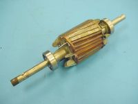
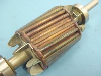
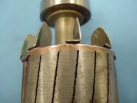
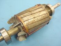
Here are some photos of the rotor from a "real" salient-pole motor from a Teletype machine. It is a 3600 RPM motor, so the rotor has two flats. When machining the flats into a rotor when converting a "standard" motor into a salient pole motor, the iron lamination material AS WELL AS PART OF THE ALUMINUM CONDUCTORS are machined away. (That why a modified motor always has less torque than it originally did.)
In a "real" salient pole motor, the iron laminations are initially created with flats, and then copper or brass rods are inserted into the core laminations as well as "outside" the flats (see photos), so ALL the conductors are present in their full, original cross-section. Some of these conductors (the ones located at the flats) are free-standing with nothing but air around them.
At the ends of the rotor, the ends of the brass rods are brazed or silver-soldered into brass end-plates to complete the electrical circuit, creating the low-resistance shorted turns.
The first photo shows both the full-diameter part of the rotor, and the free-standing brass rods over the "flat" section of the rotor.
The second photo shows a close-up of the exposed rods over the flats.
The next photo shows one of the brass end plates that the brass rods are brazed into.
The last photo shows the full-diameter part of the rotor, with the brass rods buried in the iron laminations.
The fact that part of the shorted turns is machined away in a "modified" motor explains whay the motor always has less torque than it originally did, and why it always runs hotter.
Regards,
Herr Zapp
Herr Zapp, Sat Jun 20 2009, 06:59PM
Renesis -
The answer to your question was contained in the earlier posts in this thread.
Again, see:

for photos of a typical stator, with the "dead" poles identified. A dead pole will not be encircled by any of the "run" windings. The dead poles may be harder to see on smaller motors, because there may not be a clear difference between the "run" and the "start" windings.
Remember that a squirrel-cage motor is really a rotary transformer, with the rotating magnetic field from the stator windings inducing a magnetic field in the "shorted turns" in the rotor. The "shorted turns" are created when molten aluminum is injected into and around the iron lamination stack that is the "core" of the rotor.
Here are some photos of the rotor from a "real" salient-pole motor from a Teletype machine. It is a 3600 RPM motor, so the rotor has two flats. When machining the flats into a rotor when converting a "standard" motor into a salient pole motor, the iron lamination material AS WELL AS PART OF THE ALUMINUM CONDUCTORS are machined away. (That why a modified motor always has less torque than it originally did.)
In a "real" salient pole motor, the iron laminations are initially created with flats, and then copper or brass rods are inserted into the core laminations as well as "outside" the flats (see photos), so ALL the conductors are present in their full, original cross-section. Some of these conductors (the ones located at the flats) are free-standing with nothing but air around them.
At the ends of the rotor, the ends of the brass rods are brazed or silver-soldered into brass end-plates to complete the electrical circuit, creating the low-resistance shorted turns.
The first photo shows both the full-diameter part of the rotor, and the free-standing brass rods over the "flat" section of the rotor.
The second photo shows a close-up of the exposed rods over the flats.
The next photo shows one of the brass end plates that the brass rods are brazed into.
The last photo shows the full-diameter part of the rotor, with the brass rods buried in the iron laminations.
The fact that part of the shorted turns is machined away in a "modified" motor explains whay the motor always has less torque than it originally did, and why it always runs hotter.
Regards,
Herr Zapp


Re: Synchronous rotary spark gap motor help.
Steve Conner, Sun Jun 21 2009, 09:47AM
There's no reason not to use a DC motor phase-locked by a shaft encoder. Except for the practical difficulty of getting all that circuitry to function in a high-EMI environment, knowing that if it goes wrong even once it could blow your transformer. And the theoretical difficulty of the PLL loop filter needed to lock a high-inertia motor with zero steady-state phase error.
It's easier just to build a DC resonant charging coil to go with your DC spark gap motor.
Re: Synchronous rotary spark gap motor help.
Arcstarter, Thu Jun 25 2009, 09:21PM
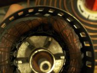
I decided to go back to using the motor posted on the first post. It turns out, it *was* synchronous after the first time i put flats. However, with the 4 inch disk it would be synchronous for a few seconds, then it would lose it for a second or so, and be sync again. I made the flats just a bit larger, and it was perfectly sync! Yay! However, the 4 inch or so disk was too small, so i made a new 6.3 or so inch disk, to make sure my flying electrodes did not hit the motor. I connected it, and now it continuously 'hunts', if that is the correct usage of that word. It never locks.
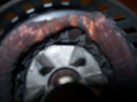
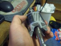
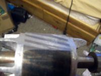
My question is should i grind it down more? Or have i ground it down too much. shows their 3450rpm motor, and it has a flat that spans about 4 entire poles, mine is almost 3 poles. The flats are aligned very well, in fact. I have two pictures, first one is showing how wide the flat on the rotor is compared to the poles on the stator. Last one is just one of the flats.
Once again, the question is take more off or have i ruined it? I think i need to take more off.
Arcstarter, Thu Jun 25 2009, 09:21PM
I decided to go back to using the motor posted on the first post. It turns out, it *was* synchronous after the first time i put flats. However, with the 4 inch disk it would be synchronous for a few seconds, then it would lose it for a second or so, and be sync again. I made the flats just a bit larger, and it was perfectly sync! Yay! However, the 4 inch or so disk was too small, so i made a new 6.3 or so inch disk, to make sure my flying electrodes did not hit the motor. I connected it, and now it continuously 'hunts', if that is the correct usage of that word. It never locks.
My question is should i grind it down more? Or have i ground it down too much.
 shows their 3450rpm motor, and it has a flat that spans about 4 entire poles, mine is almost 3 poles. The flats are aligned very well, in fact. I have two pictures, first one is showing how wide the flat on the rotor is compared to the poles on the stator. Last one is just one of the flats.
Once again, the question is take more off or have i ruined it? I think i need to take more off.


Re: Synchronous rotary spark gap motor help.
Herr Zapp, Thu Jun 25 2009, 10:37PM
Arcstarter -
You can't put back the material already removed, so you might as well take off a little more, re-test, etc, etc.
1. First, are you testing the motor with the fully assembled RSG disk attached? Unless it has the electrodes installed, it won't provide the "real" windage resistance that the motor will need to overcome. It won't do you much good to get the motor operating synchronously with a bare disk, and then install the electrodes and find it won't synch again.
2. As you can see on your rotor, the deeper you cut the more of the aluminum conductor bars are machined away. This reduces available torque. Worst-case, your motor just doesn't generate enough torque to synch up with your disk installed: you may need a bigger motor.
3. Part of your problem may be that you are trying to modify a two-speed motor. I am unaware of anyone who has ever successfully modified a multi-speed motor for salient-pole operation.
4. Several options:
a) Use a variac to boost line voltage slightly for starting. The motor will run even hotter, but for intermittent use, it may be OK. Try boosting the voltage until the motor achieves synchronism, then reduce voltage as low as possible.
b) Try substituting different start capacitors, with slightly different values. Watch out for excess current draw!
c) Try reducing the mass of the disk. Bore a few large diameter holes to remove material, or notch the periphery of the disk between electrodes. DO NOT weaken stressed areas!
If none of these help, get a bigger motor, or at least start out with a single-speed motor.
Regards,
Herr Zapp
Re: Synchronous rotary spark gap motor help.
Arcstarter, Fri Jun 26 2009, 01:02AM
This motor is a single speed motor. This is the one i wanted to use when i started the thread, you can see the picture on the first post.
Also, i decided to use this smaller disk. I will just hammer the bolts into the wood, so that they do not stick out and hit the motor. This might however crack or weaken the wood, so we will see.
So with the smaller disk, it seems to be synchronous, but if i turn it off then back on, sometimes the marks will appear to be in a different place. If i use a peice of paper, it is perfectly sync at all times.
I am thinking of how i could make a low inertia and drag rotor. I could try to cut the disk i have up, and make it just a straight piece of wood. This would reduce weight and inertia, but it might increase wind drag and reduce the strength and making the setup very unsafe. Maybe i can find something around here to use, something thinner but still tough.
Or maybe i should make the flats even bigger. Hmm, i will experiment. the motor still does not heat bad, and it is still pretty hard to make it become unsynced (no its not a word but it works) even with the disk, but like i said the spot is never showing i the right place, it changes when you stop and then restart it.
Also, i do not have a variac. I will experiment with stuff, we will see what i come up with :D
Re: Synchronous rotary spark gap motor help.
Arcstarter, Sun Jun 28 2009, 11:53PM
Well yesterday i put everything together, and i had perfect sync operation :D. I left it running for 3 hours, no overheating, nothing. I hooked it up to my Tesla coil, and i used 3 MOTs ballasted, and a 75nf 16kvdc tank cap. At first i was getting 2 foot arcs (i have a video of those), and then i took it outside.
The sparks where i am guessing over 3 feet, with 600 watts input with a single MOT unsorted in parallel with some choke i had, which pulled 5 amps measured. But sometimes it would not fire, even though i messed with the electrodes and got them extremely close to each other, no more than 1mm gap (im serious, i could here the electrodes scraping). After doing that, i went back because it was still not firing, to find nothing was wrong the the rsg, and it was still synced corrently. I tried to adjust again and i broke the disk in half (hehe, i am a retard). Oh well. I will have to make a new disk and probably the stationary electrode holding piece of wood thing...
Well, earlier today i cut a bit of iron from this bug zapper transformer i had for quite awhile to get more power. I only cut maybe 3mm or so from the shunted part, and i got much more power. So i figured i would make a tiny srsg from a MO fan. I just finished it up, and it is still perfectly sync with the disk attached (no flying electrodes yet, but i hope it wont matter). It heats up quickly, but oh well. This will be a cool mini Tesla coil :D.
I was at first skeptical it would work, but it was very easy. This might be the new thing for small Tesla coils, MO fan srsg's :D.
EDIT: Oh yea, and it is 3600rpm sync.
RE-EDIT: I finished the MO fan srsg, and it works absolutely flawlessly :D. It will start to fire at only 1kv. The screw are small however, because it would not take just a whole lot to bring the little MO fan out of sync. So that means it cannot do high powers (at least not for long, the electrodes would disappear!). I would highly suggest making one, it is free (i made mine from nothing but salvaged stuff, including the electrodes) and works well. Though the motor heating is a bit bad... Not too much worse than before though.
Re: Synchronous rotary spark gap motor help.
Arcstarter, Tue Jun 30 2009, 11:06PM
I made a video of the Tesla coil operating indoors with only ~2 foot sparks (i did not have my camcorder when i achieved the 3+ foot ground arcs). The sound is weird when the coil is operating on the video. It sounds much higher pitch than that, like a true srsg coil -.-.

Print this page