
"MMI 1" - New DRSSTC
tesla500, Sat Feb 07 2009, 09:35AMHey guys,
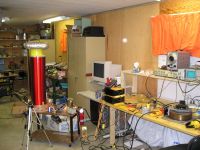
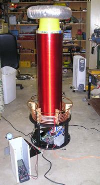
I recently got a lot of work done on my first DRSSTC. I went for a medium size coil, about as big as is practical to run indoors.
Specs:
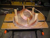
Primary: 6T 3/8" copper tube, 1/4" spacing, 15" diameter vertical helix. Tapped at around 5T
Primary cap: 0.52uF 4.8kV made of 1.2kV 0.68uF GE film caps
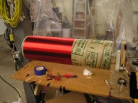
Secondary: 10"x32" 26AWG on sonotube
Toroid: 4x14" really banged up toroid from an old coil, for testing. Probably 6x16 or so for the final version.
Frequency: 64kHz with current toroid
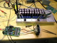
Control: My own PCB layout, based heavily on Steve Ward's controller with beefed up FET drive and a metal housing fiber receiver.
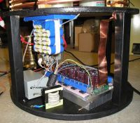
Inverter: Full bridge, currently using 3x HGTG20N60A4D IGBTs on each leg, room for 5.
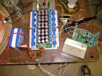
I wasn't keen on using expensive or hard to find IGBTs, so I went for an "MMI" approach, with several cheap TO-247 IGBTs in parallel in a full bridge. The bus cap is also composed of many small caps in parallel, 30x 150uF 400V high ripple electrolytics, giving a very low inductance, in about 1/4 the volume of a single large cap of similar ratings.
Schematics of the control and inverter boards are attached below the pictures. I can post Altium source files or gerbers if you'd like, and I have a few of the PCBs available if anyone is interested.
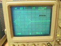
Currently I'm running it off a rectified 120V variac, but eventually I'll modify the boost PFC stage from a scrap battery charger from work to supply 385VDC. Max sparks achieved so far are about 3' long, running at 150VDC and around 500Apk for 200uS burst length, 120Hz pulse rate. I'm starting to have problems of arcs breaking out of the strike rail and hitting the secondary when going longer than about 3', perhaps the wood primary mounts weren't such a good idea, or the strike rail needs to be lowered.
David
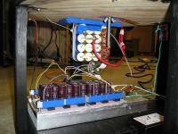
]control.pdf[/file]
]power.pdf[/file]
Re: "MMI 1" - New DRSSTC
101111, Sat Feb 07 2009, 04:59PM
Oh my!.... :O
This looks fantastic, keep on the good work.
101111, Sat Feb 07 2009, 04:59PM
Oh my!.... :O
This looks fantastic, keep on the good work.
Re: "MMI 1" - New DRSSTC
Tom540, Sat Feb 07 2009, 05:19PM
Hey that looks awesome! I like that bridge layout. I love those IGBT's too. I'm suprised about your wood primary supports. Ive tried it a few time and both times I had the wood break between turns. I wasn't using plywood though. I might have to give that another try. I would say lower or widen the strike rail. im not sure what wood supports would have to do with those strikes you're getting.
Re: "MMI 1" - New DRSSTC
MRacerxdl, Sat Feb 07 2009, 05:32PM
Wow, that is a very impressive setup! Very good work!
MRacerxdl, Sat Feb 07 2009, 05:32PM
Wow, that is a very impressive setup! Very good work!
Re: "MMI 1" - New DRSSTC
tesla500, Sat Feb 07 2009, 07:04PM
Thanks guys!
I'll try lowering the strike rail and see how that works. I was pretty careful with the wood supports, I baked them at 125C for several hours, then dipped them in varnish to keep them dry. I was almost going to use plain wood instead of plywood, probably a good thing I went with plywood instead, if plain wood breaks easily.
David
Re: "MMI 1" - New DRSSTC
..., Sat Feb 07 2009, 07:06PM
Wow that really is amazign looking!
Good job with getting all of your bridges working together happily, I have seen a few failed projects trying to make that work!
Sounds like a geat coil
..., Sat Feb 07 2009, 07:06PM
Wow that really is amazign looking!
Good job with getting all of your bridges working together happily, I have seen a few failed projects trying to make that work!
Sounds like a geat coil

Re: "MMI 1" - New DRSSTC
101111, Sat Feb 07 2009, 07:27PM
There is one thing I think you can improve: The Alu bars going over the IGBTs to keep them tight to the heat sink should have one screw between each IGBT for best thermal contact, and you should also use thermal grease.
101111, Sat Feb 07 2009, 07:27PM
There is one thing I think you can improve: The Alu bars going over the IGBTs to keep them tight to the heat sink should have one screw between each IGBT for best thermal contact, and you should also use thermal grease.
Re: "MMI 1" - New DRSSTC
tesla500, Sat Feb 07 2009, 08:49PM
Yep, moving the strike rail down fixed it, at least for operation at 200VDC.
The Al bars are solid 1/2" square, have silicone model airplane fuel line under them to provide even pressure, and there's a phase change thermal material between the IGBTs and the heatsink. It's a 2mil Kapton sheet with aluminum oxide powder mixed with wax coated on each side. When the devices heat up and the wax melts, it becomes just like thermal grease.
I'm currently removing the PFC stage from the scrap battery charger, then I can test at higher bus voltage.
David
Re: "MMI 1" - New DRSSTC
GeordieBoy, Sun Feb 08 2009, 12:13AM
Neat layout and neat PCBs too. 3ft sparks sounds good for only 150VDC bus voltage.
You shouldn't have any problems with the active PFC pre-converter provided that you keep it's own DC bus capacitor present, and then connect it's output to your inverter boards. You can put a ferrite common-mode choke over this cable carrying power from the PFC to the inverter. This choke will prevent hash from the DRSSTC inverter from getting back into the PFC controller.
The only problem you might experience is one of high inrush current due to all of those paralleled electrolytics on your DRSSTC inverter boards!!! This inrush might blow the delicate fast-diode in your PFC pre-converter if it's from a dinky power supply and doesn't incorporate soft-start resistors.
-Richie,
Re: "MMI 1" - New DRSSTC
tesla500, Sun Feb 08 2009, 07:59AM
Good progress on the PFC, it still works after cutting the charger in half. I replaced the stock silicon PFC diode with a 10A 600V silicon carbide schottky for operation at higher power. This PFC should be good to about 12A mains draw from 120V to 240V now.
I was hoping to get away with a smaller cap on the PFC output, using the inverter bus caps to do most of the filtering, but it looks like that won't work, the small electrolytic I tried got warm quickly. Shouldn't have cut the heatsinks so short, I'll need to cram the original caps back into the case somehow.
Inrush shouldn't be a problem. This charger has a precharge resistor with a relay that shorts it out about 1 second after plug in. A bigger resistor certainly will be needed, there's 10x as much bus capacitance now! The original was 100ohm 1W, I've got a 16ohm 30W wirewound that should do nicely. I'll also add a diode from input bridge positive to bus positive, so if the PFC shuts down for some reason the SiC diode won't have to take the large peak currents.
David
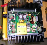
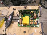
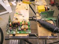
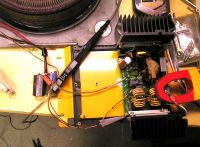
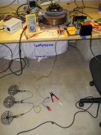


Re: "MMI 1" - New DRSSTC
tesla500, Sun Feb 08 2009, 10:30AM
Update - I've gotten several PMs asking for the gerbers. I've attached all the design info in a zip file, including schematcs and PCBs in pdf, the Altium Designer Summer 08 project, and gerbers. If you want the project in some other format, don't hesitate to ask, I'll see what I can export it to.
Do note that there are a couple of errors as there usually are on a first run of boards. The gate drive voltage pot on the control board is wired wrong, so the gate drive voltage regulator setting is fixed with a resistor. On the inverter board, the terminal strips that the IGBTs connect to are about 0.4mm too narrow, so the leads need to be bent a little bit to fit. No terminal strips are available that fit the IGBTs perfectly.
David
]drsstc_boards.zip[/file]
Re: "MMI 1" - New DRSSTC
GeordieBoy, Sun Feb 08 2009, 01:05PM
Looking at the pictures I'd say you definitely need to keep some low ESR electrolytics right at the PFC converter. Stray inductance in the MOSFET/diode/output cap loop of a PFC circuit needs to be kept extremely low to prevent voltage spikes when the MOSFET turns off. I'm suprised you didn't blow the switching transistor from over voltage by putting the electrolytics at the end of flying leads!
The Inrush-bypass diode is definitely a good idea. If you make this a beefy conventional silicon diode it will also likely protect the PFC stage in the event of a DC bus short if the inverter fails.
> This PFC should be good to about 12A mains draw from 120V to 240V now.
It will likely power limit at slightly more than the original design power because the voltage loop will run out of headroom, that is what normally happens. Even though all components can stand the voltages associated with 240V operation, and the currents associated with 110V operation, the control loop often cannot make this combination of voltage and current available at the same time without being modified.
I successfully modified an active PFC stage from a 150W PSU to deliver 1500W in a SSTC application, but I think I had to change about 22 individual things to get there!
-Richie,
Re: "MMI 1" - New DRSSTC
tesla500, Sun Feb 08 2009, 08:16PM
I did have a 100uF cap placed where the original caps were on the PCB to handle the fast spikes. I took a look at the current through the wires between that cap and the external caps (440uF), and it seems most of the ripple is being handled by the external caps, but the high frequency components that the 100uF cap had to handle were making it get quite hot.
Here's a shot of the current through the wires between the 100uF cap on the PCB and the 440uF external cap, 4A/div
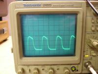
I took a look at the control loop, and there seems to be lots of headroom in this design, I calculate about a 12A max draw at 240V based on what the voltage loop can demand.
David
tesla500, Sun Feb 08 2009, 08:16PM
GeordieBoy wrote ...
Looking at the pictures I'd say you definitely need to keep some low ESR electrolytics right at the PFC converter. Stray inductance in the MOSFET/diode/output cap loop of a PFC circuit needs to be kept extremely low to prevent voltage spikes when the MOSFET turns off. I'm suprised you didn't blow the switching transistor from over voltage by putting the electrolytics at the end of flying leads!
Looking at the pictures I'd say you definitely need to keep some low ESR electrolytics right at the PFC converter. Stray inductance in the MOSFET/diode/output cap loop of a PFC circuit needs to be kept extremely low to prevent voltage spikes when the MOSFET turns off. I'm suprised you didn't blow the switching transistor from over voltage by putting the electrolytics at the end of flying leads!
I did have a 100uF cap placed where the original caps were on the PCB to handle the fast spikes. I took a look at the current through the wires between that cap and the external caps (440uF), and it seems most of the ripple is being handled by the external caps, but the high frequency components that the 100uF cap had to handle were making it get quite hot.
Here's a shot of the current through the wires between the 100uF cap on the PCB and the 440uF external cap, 4A/div

GeordieBoy wrote ...
> This PFC should be good to about 12A mains draw from 120V to 240V now.
It will likely power limit at slightly more than the original design power because the voltage loop will run out of headroom, that is what normally happens. Even though all components can stand the voltages associated with 240V operation, and the currents associated with 110V operation, the control loop often cannot make this combination of voltage and current available at the same time without being modified.
I successfully modified an active PFC stage from a 150W PSU to deliver 1500W in a SSTC application, but I think I had to change about 22 individual things to get there!
I took a look at the control loop, and there seems to be lots of headroom in this design, I calculate about a 12A max draw at 240V based on what the voltage loop can demand.
David
Re: "MMI 1" - New DRSSTC
GeordieBoy, Sun Feb 08 2009, 09:40PM
For PFC design I normally work on the basis of 1uF per watt of power when the DC bus voltage is 400V. This capacitance can be split equally between the PFC output and the inverter input with a common-mode choke in between. For 12A draw off 240VAC that works out at about 1400uF at the PFC output, and another 1400uF across the DC bus at the inverter. A single 100uF electrolytic right at the PFC is almost certainly unable to support the ripple if you've loaded it up to nearly 3kW.
-Richie,
Re: "MMI 1" - New DRSSTC
tesla500, Mon Feb 09 2009, 08:25AM
Well, I've had my first IGBT failure, while trying the coil out at higher bus voltages. I had no problems running up to about 350V, the problem occurred the first firing at 395V. I was running about a 75-100uS burst with a peak current of maybe 600-700A. I'm not sure if the IGBTs started the failure, one of the bus caps had its leads vaporized and was sent flying.
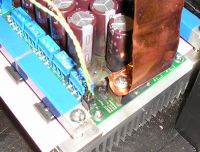
There appears to be arcing between bus + (lower pad on capacitor) and the half bridge output (top layer):
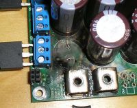
I'm not quite sure if the IGBTs failed first, or the cap. Only two IGBTs failed, both on the negative leg of the H bridge, the same side as the capacitor failure. The remaining bus caps recharged after the loud bang, no fuses blew, and no IGBT cases cracked. I was also [luckily not] shocked that the failed cap still had voltage on it after cutting it open! I don't see any damage inside the cap, it appears only the leads were blown off.
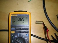
I've got two theories how the failure occurred.
1: High voltage and high dv/dt on the bridge output caused tracking and an arc between the bridge output and bus +. The arc continued and vaporized the leads on one of the capacitors, and the high current through the IGBTs caused the low side ones to fail.
2: A weakened lead on one capacitor breaks under high current, causing an arc. This arc continues and makes its way between bus + and bridge output, and the high current causes the low side IGBTs to fail short circuit.
In either case, once the IGBT's gates have short circuited to ground, the gate driver shouldn't be able to drive the gates high on opposite leg's IGBTs, so shoot through doesn't cause a massive failure of all the IGBTs in that side of the H bridge. If this is the case, an initial IGBT failure shouldn't be able to cause massive shoot through current on the bus caps, so I can't see that causing a cap to blow up.
Any other ideas/insight?
These chargers run much smaller bus caps, about 0.4uF/W. I think that's because there's no hold up time requirement, the only limits are ripple rating and heating. I've got the original 440uF worth of caps back in the PFC stage now.
David
tesla500, Mon Feb 09 2009, 08:25AM
Well, I've had my first IGBT failure, while trying the coil out at higher bus voltages. I had no problems running up to about 350V, the problem occurred the first firing at 395V. I was running about a 75-100uS burst with a peak current of maybe 600-700A. I'm not sure if the IGBTs started the failure, one of the bus caps had its leads vaporized and was sent flying.

There appears to be arcing between bus + (lower pad on capacitor) and the half bridge output (top layer):

I'm not quite sure if the IGBTs failed first, or the cap. Only two IGBTs failed, both on the negative leg of the H bridge, the same side as the capacitor failure. The remaining bus caps recharged after the loud bang, no fuses blew, and no IGBT cases cracked. I was also [luckily not] shocked that the failed cap still had voltage on it after cutting it open! I don't see any damage inside the cap, it appears only the leads were blown off.

I've got two theories how the failure occurred.
1: High voltage and high dv/dt on the bridge output caused tracking and an arc between the bridge output and bus +. The arc continued and vaporized the leads on one of the capacitors, and the high current through the IGBTs caused the low side ones to fail.
2: A weakened lead on one capacitor breaks under high current, causing an arc. This arc continues and makes its way between bus + and bridge output, and the high current causes the low side IGBTs to fail short circuit.
In either case, once the IGBT's gates have short circuited to ground, the gate driver shouldn't be able to drive the gates high on opposite leg's IGBTs, so shoot through doesn't cause a massive failure of all the IGBTs in that side of the H bridge. If this is the case, an initial IGBT failure shouldn't be able to cause massive shoot through current on the bus caps, so I can't see that causing a cap to blow up.
Any other ideas/insight?
GeordieBoy wrote ...
For PFC design I normally work on the basis of 1uF per watt of power when the DC bus voltage is 400V. This capacitance can be split equally between the PFC output and the inverter input with a common-mode choke in between. For 12A draw off 240VAC that works out at about 1400uF at the PFC output, and another 1400uF across the DC bus at the inverter. A single 100uF electrolytic right at the PFC is almost certainly unable to support the ripple if you've loaded it up to nearly 3kW.
-Richie,
These chargers run much smaller bus caps, about 0.4uF/W. I think that's because there's no hold up time requirement, the only limits are ripple rating and heating. I've got the original 440uF worth of caps back in the PFC stage now.
David
Re: "MMI 1" - New DRSSTC
GeordieBoy, Mon Feb 09 2009, 11:27AM
The voltage and dv/dt produced at the output of a 400V IGBT bridge is not sufficient to initiate breakdown of FR4 laminate. Flyback SMPSUs with reflected voltages in the high hundreds of volts typically only use a few millimetres of creapage distance over similar material without any problems.
If there are traces of carbon tracking then it is probably a common-mode noise problem between the DC bus and mains earth. Do you have common-mode capacitors from DC bus - to earth and DC bus + to earth?
My theory for the dramatic failure would be this:
One of the 400V electrolytics developed an internal short, (395V is too close to the 400V rated voltage, especially when you consider that the capacitors are likely being thrashed in terms of their RMS current ripple rating too. Are they new devices or pulls from old equipment?) The remaining bank of paralleled capacitors discharged into the shorted component fusing its connecting leads and sending it flying across the room.
Were you running the coil from the active PFC pre-converter when the failure occured? The output voltage of an active PFC pre-converters is only semi-regulated, and the voltage loop has a sluggish response time. When an active PFC stage is presented with a pulsed load on the DC bus it wouldn't be uncommon for the bus voltage to sag and then overshoot considerably after each "bang" of the DRSSTC. The bus caps are usually rated at 450VDC for a 380VDC boost voltage and the over-voltage trip should be set around 425.
-Richie,
Re: "MMI 1" - New DRSSTC
tesla500, Mon Feb 09 2009, 06:13PM
I do have a 22nF cap from bus - to ground. Early on I had the ground fall off and cause some arcing between the heatsink and somewhere under the board, as the secondary base current found the easiest path to ground through the mains. I added the cap at that point, and didn't have any problem until now.
These are new caps. I thought about an internal short too, but discounted it when I found that the failed cap still held a charge. Could a short circuit blow itself clear and let the cap still hold a charge? I'll unroll the failed cap later and see if there's evidence of an internal short.
It was running off a variac at the time.
This battery charger has 400V rated bus caps, so they're pushing the ratings too.
David
tesla500, Mon Feb 09 2009, 06:13PM
GeordieBoy wrote ...
If there are traces of carbon tracking then it is probably a common-mode noise problem between the DC bus and mains earth. Do you have common-mode capacitors from DC bus - to earth and DC bus + to earth?
If there are traces of carbon tracking then it is probably a common-mode noise problem between the DC bus and mains earth. Do you have common-mode capacitors from DC bus - to earth and DC bus + to earth?
I do have a 22nF cap from bus - to ground. Early on I had the ground fall off and cause some arcing between the heatsink and somewhere under the board, as the secondary base current found the easiest path to ground through the mains. I added the cap at that point, and didn't have any problem until now.
GeordieBoy wrote ...
My theory for the dramatic failure would be this:
One of the 400V electrolytics developed an internal short, (395V is too close to the 400V rated voltage, especially when you consider that the capacitors are likely being thrashed in terms of their RMS current ripple rating too. Are they new devices or pulls from old equipment?) The remaining bank of paralleled capacitors discharged into the shorted component fusing its connecting leads and sending it flying across the room.
These are new caps. I thought about an internal short too, but discounted it when I found that the failed cap still held a charge. Could a short circuit blow itself clear and let the cap still hold a charge? I'll unroll the failed cap later and see if there's evidence of an internal short.
GeordieBoy wrote ...
Were you running the coil from the active PFC pre-converter when the failure occured? The output voltage of an active PFC pre-converters is only semi-regulated, and the voltage loop has a sluggish response time. When an active PFC stage is presented with a pulsed load on the DC bus it wouldn't be uncommon for the bus voltage to sag and then overshoot considerably after each "bang" of the DRSSTC. The bus caps are usually rated at 450VDC for a 380VDC boost voltage and the over-voltage trip should be set around 425.
Were you running the coil from the active PFC pre-converter when the failure occured? The output voltage of an active PFC pre-converters is only semi-regulated, and the voltage loop has a sluggish response time. When an active PFC stage is presented with a pulsed load on the DC bus it wouldn't be uncommon for the bus voltage to sag and then overshoot considerably after each "bang" of the DRSSTC. The bus caps are usually rated at 450VDC for a 380VDC boost voltage and the over-voltage trip should be set around 425.
It was running off a variac at the time.
This battery charger has 400V rated bus caps, so they're pushing the ratings too.
David
Re: "MMI 1" - New DRSSTC
tesla500, Tue Feb 10 2009, 03:13AM
Update:
I unrolled the blown capacitor, and it didn't fail internally. There's no sign whatsoever of internal breakdown.
I really need a digital scope so I can see what happens during the failure...

tesla500, Tue Feb 10 2009, 03:13AM
Update:
I unrolled the blown capacitor, and it didn't fail internally. There's no sign whatsoever of internal breakdown.
I really need a digital scope so I can see what happens during the failure...
Re: "MMI 1" - New DRSSTC
tesla500, Mon Feb 16 2009, 06:41AM
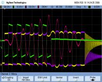
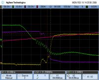
I think I may have a lead on the cause of the failure. I notice that at high primary currents, the hi to lo transition of H bridge output '1' is being delayed significantly This delay doesn't occur when the primary current is low. The delay is shown in the scope shots below:
Setup: 200VDC bus, no secondary, 90uS burst length
Channels:
1: H bridge side 1 output WRT bus (-)
2: H bridge side 1 low side IGBT gate vs. ground WRT bus (-)
3: H bridge side 2 output vs. ground WRT bus (-)
4: Primary current, 200A/div
Overview of burst, ~650A peak:
Side 1 hi to low transition, delayed 150ns from side 2. The slew rate of the transition also looks slower on side 1 compared to side 2. Also, the miller plateau lasts for less than 100nS, while the plateau on the other side (not shown) lasts about 200nS:
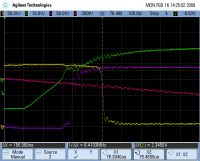
Side 1 lo to hi transition. Much better matched with side 2:
I've checked that every gate resistor and diode is fine, and all the gate drive transformer outputs have the same drive capability of 4A peak driving a short circuit. This delay doesn't appear on the other side of the H bridge, which is for the most part a mirror image of the problem side. I'm doubtful the problem is due to layout given the other side is fine.
The only thing I can think of that would cause this delay is a damaged TVS. I'm using bi-directional TVSs to stop the TVS diode from taking any current that should be handled by the IGBT anti-parallel diodes. If one of the two anti-series diodes in the TVS went short circuit, then perhaps the freewheeling current would be handled by the slow TVS, and the slow reverse recovery is holding the side 1 voltage high.
Does this theory sound reasonable, or am I completely barking up the wrong tree?
David
tesla500, Mon Feb 16 2009, 06:41AM
I think I may have a lead on the cause of the failure. I notice that at high primary currents, the hi to lo transition of H bridge output '1' is being delayed significantly This delay doesn't occur when the primary current is low. The delay is shown in the scope shots below:
Setup: 200VDC bus, no secondary, 90uS burst length
Channels:
1: H bridge side 1 output WRT bus (-)
2: H bridge side 1 low side IGBT gate vs. ground WRT bus (-)
3: H bridge side 2 output vs. ground WRT bus (-)
4: Primary current, 200A/div
Overview of burst, ~650A peak:

Side 1 hi to low transition, delayed 150ns from side 2. The slew rate of the transition also looks slower on side 1 compared to side 2. Also, the miller plateau lasts for less than 100nS, while the plateau on the other side (not shown) lasts about 200nS:

Side 1 lo to hi transition. Much better matched with side 2:

I've checked that every gate resistor and diode is fine, and all the gate drive transformer outputs have the same drive capability of 4A peak driving a short circuit. This delay doesn't appear on the other side of the H bridge, which is for the most part a mirror image of the problem side. I'm doubtful the problem is due to layout given the other side is fine.
The only thing I can think of that would cause this delay is a damaged TVS. I'm using bi-directional TVSs to stop the TVS diode from taking any current that should be handled by the IGBT anti-parallel diodes. If one of the two anti-series diodes in the TVS went short circuit, then perhaps the freewheeling current would be handled by the slow TVS, and the slow reverse recovery is holding the side 1 voltage high.
Does this theory sound reasonable, or am I completely barking up the wrong tree?
David
Re: "MMI 1" - New DRSSTC
Tom540, Mon Feb 16 2009, 06:33PM
I think it sounds reasonable to me. Ive actually damaged an IGBT's gate that caused it to act weird very much like what you're describing. It wouldn't blow the 5 amp fuse and the coil still worked but just not very well.
Tom540, Mon Feb 16 2009, 06:33PM
I think it sounds reasonable to me. Ive actually damaged an IGBT's gate that caused it to act weird very much like what you're describing. It wouldn't blow the 5 amp fuse and the coil still worked but just not very well.
Re: "MMI 1" - New DRSSTC
tesla500, Tue Feb 17 2009, 09:03AM
Ahhh, found the problem causing the asymmetric waveforms: Two terminal strips that the IGBTs connect to had their middle terminal (IGBT collector) blow open, so only one IGBT was working on one leg. I really didn't expect those to fail, the leads look solid, and have almost as much area as the IGBT leads.
Still no explanation for the initial failure, though. I'll just have to fire it again at the same conditions, and capture it with the scope this time to see exactly what happens, if it fails again.
David
Re: "MMI 1" - New DRSSTC
Electroholic, Tue Feb 17 2009, 09:58AM
Don't know which type of screw terminals you got, but I've had problems with solder joint cracking when torquing things down. Mine had a 1.1mm round pin, but I have seen others with square pins.
Electroholic, Tue Feb 17 2009, 09:58AM
Don't know which type of screw terminals you got, but I've had problems with solder joint cracking when torquing things down. Mine had a 1.1mm round pin, but I have seen others with square pins.
Re: "MMI 1" - New DRSSTC
hvguy, Tue Feb 17 2009, 09:07PM
That looks like a classic flash over to me. I know, people are going to say there is not enough voltage there, but I have built over a hundred DRSSTCs and I have seen several failures due to flash overs on the PCB. The di/dt, and consequent dv/dt in these systems is quite fast and can cause spikes in the several kv range that are only a few ns long. These tend to flash PCBs over. I once had a system fail because a flash over occurred from one trace, to the can of a ltyic (through the plastic), and back to another trace. This resulted in the bus shorting and blowing a large hole in the affected traces and the cap can.
Check your trace spacing and insulate anything suspect with silicon. I also use kapton tape under my lytics when the can runs on top of or near a trace.
Your bridge to ground bypass cap, .022uF, could be larger. I know the impedance is already "really low" (113ohms), but I have had better experiences with caps in the 1uF range. This is likely due to the fact that a secondary to primary arc can carry over 100Apk from a system your size, that would mean 11Kv across that 22nF cap... Also, this all could have been caused by a primary-secondary flash over that you did not notice.
Re: "MMI 1" - New DRSSTC
Steve Conner, Wed Feb 18 2009, 10:58AM
If you get just the wrong value of bridge bypass cap, it can go into parallel resonance with the stray inductances of your buswork, and blow even more things up.
Steve Conner, Wed Feb 18 2009, 10:58AM
If you get just the wrong value of bridge bypass cap, it can go into parallel resonance with the stray inductances of your buswork, and blow even more things up.
Re: "MMI 1" - New DRSSTC
tesla500, Sun Feb 22 2009, 07:46AM
Got the bridge fixed, it turned out to be blown through-hole plating on the PCB. I didn't hold the soldering iron in place long enough when soldering in the terminal strips, so the solder didn't wick through all the way.
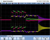
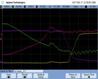
I fired the bridge at 400V 860Apk, and no failure occurred (no secondary in place):
Channels:
1: H bridge side 1 output WRT bus (-)
2: H bridge side 1 low side IGBT gate vs. ground WRT bus (-)
3: H bridge side 2 output vs. ground WRT bus (-)
4: H bridge side 2 low side IGBT gate vs. ground WRT bus (-)
Overview, note the lack of overshoot on the outputs:
Last (highest current) switching edge, quite clean, switching time ~50ns
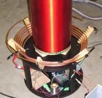
I modified the primary coil into a conical saucer to give more clearance to the secondary to prevent arc overs:
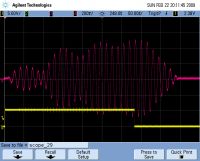
I also took a bunch of scope shots of the primary current at various primary tap points, below and above the secondary fres. 200A/div, single shot, bus voltage 100V. I've made them into animated GIFs:
Wide range, 3 11/12 to 4 9/12 turns, 1/12 turn per step:
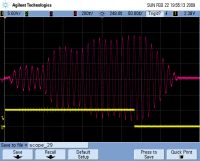
Narrow range around secondary Fres, showing sudden change of mode. 4 2/36 to 4 7/36 turns in 1/36 turn steps. Note the sudden jump early on, it occurs somewhere in the middle of the primary support so I can't get any more points in between.
Now all I have to do is work up the courage to fire it at full 400V bus voltage.
David
tesla500, Sun Feb 22 2009, 07:46AM
Got the bridge fixed, it turned out to be blown through-hole plating on the PCB. I didn't hold the soldering iron in place long enough when soldering in the terminal strips, so the solder didn't wick through all the way.
I fired the bridge at 400V 860Apk, and no failure occurred (no secondary in place):
Channels:
1: H bridge side 1 output WRT bus (-)
2: H bridge side 1 low side IGBT gate vs. ground WRT bus (-)
3: H bridge side 2 output vs. ground WRT bus (-)
4: H bridge side 2 low side IGBT gate vs. ground WRT bus (-)
Overview, note the lack of overshoot on the outputs:

Last (highest current) switching edge, quite clean, switching time ~50ns

I modified the primary coil into a conical saucer to give more clearance to the secondary to prevent arc overs:

I also took a bunch of scope shots of the primary current at various primary tap points, below and above the secondary fres. 200A/div, single shot, bus voltage 100V. I've made them into animated GIFs:
Wide range, 3 11/12 to 4 9/12 turns, 1/12 turn per step:

Narrow range around secondary Fres, showing sudden change of mode. 4 2/36 to 4 7/36 turns in 1/36 turn steps. Note the sudden jump early on, it occurs somewhere in the middle of the primary support so I can't get any more points in between.

Now all I have to do is work up the courage to fire it at full 400V bus voltage.

David
Re: "MMI 1" - New DRSSTC
Steve Conner, Sun Feb 22 2009, 03:07PM
Hi David,
That's interesting that you managed to catch the mode hopping effect.
With all this scopey goodness at your disposal, could you try one more experiment for us? Capture the feedback signal after the limiting amp, or the H-bridge output, just basically any stage after it's been squared up, and take the FFT of it.
I always had a hunch that with a Steve Ward style driver, the whole system, H-bridge and all, might run at two frequencies simultaneously. If you can see two frequencies in your FFT, that might prove it.
The PLL-driven coils that I made must settle to one resonant frequency or the other, by definition of the way a PLL works, and they don't show those beats in the envelope, they just ring up monotonically.
Re: "MMI 1" - New DRSSTC
GeordieBoy, Sun Feb 22 2009, 05:53PM
David those are great animated GIFs showing real-life behaviours. That's a nice scope to have available for this sort of work. I have one on my desk at work, although rarely risk bringing it close to a SSTC!
What sort of spark length variation did you observe during your narrow tuning variation testing? BTW You can prevent the mode switching behaviour you observed by taking the inverter feedback from the secondary base-current instead of the primary current. The secondary base current experiences two pole pairs so swings through 360 degrees from DC to infinity, where as the primary current swings through the same 180 degrees twice. That's why the mode hopping happens with primary feedback. With secondary base-current feedback you can choose either the upper or lower operating mode by swapping the polarity of the wires from the CT, or by running the secondary base-wire through the CT the other way.
Steve:
An FFT of any of those waveforms with even the slightest ripple envelope will show two dominant frequencies. Only something like a gausian amplitude envelope will show a single RF frequency with no sidebands. Once there is any hint of amplitude modulation there will be at least one other frequency present. Obviously the most severe case is where obvious phase inversions are clearly visible in the carrier. In this case the energy in the two modes must be very similar to cause such deep cancellation.
An FFT of the inverter output should show two dominant spectral lines at the two mode frequencies f1 and f2, then a whole set of intermod products like f1-f2 f1+f2 2f1+f2 2f1-f2 2f2+f1 2f2-f1 2f1+2f2 2f1-2f2 etc... etc...
Even the PLL driven coils with the single frequency excitation will still show two spectral lines in the current waveform because the boxcar gated RF burst used to excite the 4th order system still contains spectral energy at all frequencies. The only way not to excite both modes is to use a sinewave at a single mode frequency that has existed since the big-bang and will keep going at constant amplitude for ever more!
-Richie,
GeordieBoy, Sun Feb 22 2009, 05:53PM
David those are great animated GIFs showing real-life behaviours. That's a nice scope to have available for this sort of work. I have one on my desk at work, although rarely risk bringing it close to a SSTC!
What sort of spark length variation did you observe during your narrow tuning variation testing? BTW You can prevent the mode switching behaviour you observed by taking the inverter feedback from the secondary base-current instead of the primary current. The secondary base current experiences two pole pairs so swings through 360 degrees from DC to infinity, where as the primary current swings through the same 180 degrees twice. That's why the mode hopping happens with primary feedback. With secondary base-current feedback you can choose either the upper or lower operating mode by swapping the polarity of the wires from the CT, or by running the secondary base-wire through the CT the other way.
Steve:
An FFT of any of those waveforms with even the slightest ripple envelope will show two dominant frequencies. Only something like a gausian amplitude envelope will show a single RF frequency with no sidebands. Once there is any hint of amplitude modulation there will be at least one other frequency present. Obviously the most severe case is where obvious phase inversions are clearly visible in the carrier. In this case the energy in the two modes must be very similar to cause such deep cancellation.
An FFT of the inverter output should show two dominant spectral lines at the two mode frequencies f1 and f2, then a whole set of intermod products like f1-f2 f1+f2 2f1+f2 2f1-f2 2f2+f1 2f2-f1 2f1+2f2 2f1-2f2 etc... etc...
Even the PLL driven coils with the single frequency excitation will still show two spectral lines in the current waveform because the boxcar gated RF burst used to excite the 4th order system still contains spectral energy at all frequencies. The only way not to excite both modes is to use a sinewave at a single mode frequency that has existed since the big-bang and will keep going at constant amplitude for ever more!

-Richie,
Re: "MMI 1" - New DRSSTC
tesla500, Mon Feb 23 2009, 04:59AM
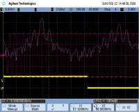
I got a couple of FFTs done, one of the primary current, and one of the relatively well clipped primary current.
The primary current FFT shows two distinct frequencies, 57 and 68khz. 0-100kHz FFT span:
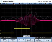
I clipped the primary current by turning the V/div way up, the edges of the waveform are about 1/10th the period. This shows the intermod products like Richie mentioned, but doesn't show the 68kHz as clearly as the above FFT. 0-200kHz FFT span:
Unfortunately I wasn't paying much attention to the spark length, it was breaking out into open air, and wasn't very long, maybe 6" to 1'.
What benefits do base current or PLL based feedback have? They do seem to not guarantee ZCS or near ZCS. I'm a little concerned because the IGBTs I'm using have a max current rating of 280A, but a switching SOA only up to 100A. The present driver seems to switch at <100A at 800A primary current, and that's spread over all the IGBTs.
For scope safety, what would you recommend? I've got the scope quite a good distance away, with a grounded metal shield between the scope and the coil, when running with the secondary in place at low power. Current is being measured with an old Tek current probe clamped on the 1024:1 feedback CT line going to the control board. The probe amp is grounded through its cord to mains ground. I've also got an old computer/accessories (that I don't really care about) about 4' away from the coil, and they're still working perfectly.
Still, to be safe I'll probably switch back to the other cheaper scope for high power testing.
David
tesla500, Mon Feb 23 2009, 04:59AM
I got a couple of FFTs done, one of the primary current, and one of the relatively well clipped primary current.
The primary current FFT shows two distinct frequencies, 57 and 68khz. 0-100kHz FFT span:

I clipped the primary current by turning the V/div way up, the edges of the waveform are about 1/10th the period. This shows the intermod products like Richie mentioned, but doesn't show the 68kHz as clearly as the above FFT. 0-200kHz FFT span:

Unfortunately I wasn't paying much attention to the spark length, it was breaking out into open air, and wasn't very long, maybe 6" to 1'.
What benefits do base current or PLL based feedback have? They do seem to not guarantee ZCS or near ZCS. I'm a little concerned because the IGBTs I'm using have a max current rating of 280A, but a switching SOA only up to 100A. The present driver seems to switch at <100A at 800A primary current, and that's spread over all the IGBTs.
For scope safety, what would you recommend? I've got the scope quite a good distance away, with a grounded metal shield between the scope and the coil, when running with the secondary in place at low power. Current is being measured with an old Tek current probe clamped on the 1024:1 feedback CT line going to the control board. The probe amp is grounded through its cord to mains ground. I've also got an old computer/accessories (that I don't really care about) about 4' away from the coil, and they're still working perfectly.
Still, to be safe I'll probably switch back to the other cheaper scope for high power testing.
David
Re: "MMI 1" - New DRSSTC
GeordieBoy, Wed Feb 25 2009, 12:32AM
> What benefits do base current or PLL based feedback have?
I have not used PLL feedback myself but i'd imagine that you can tailor the capture and tracking ranges of the PLL to confine operation to the upper or lower mode as you wish.
Base current feedback allows you to switch between the modes by reversing the polarity of feedback. However, it doesn't guarantee that the actual output current of the inverter is in phase with the voltage. It only guarantees that the base current of the resonator is in-phase with the inverter output voltage. This means that the inverter can end up hard-switching a significant leading or lagging load current if the secondary is arcing to ground. As you said this could exceed the commutating safe operating area in which your IGBTs can safely turn off.
> For scope safety, what would you recommend?
Ermm, Don't put it anywhere near a Tesla Coil!?!?
Seriously though it should be okay if you are careful. Good attention to grounding, and use of CT's and isolation probes should keep it happy. Just don't exceed the voltage rating of the probes, especially if the allowable voltage specification derates with increasing frequency. Running the SSTC off an isolation transformer is best if you are going to scope the power side, but I'm guessing that you're doing that already from the traces you've posted previously.
The most likely first sign of trouble would be crashing or rebooting of the scope's operating system. The Agilent DSO6034 that I have on my bench at work seems very robust though.
-Richie,
GeordieBoy, Wed Feb 25 2009, 12:32AM
> What benefits do base current or PLL based feedback have?
I have not used PLL feedback myself but i'd imagine that you can tailor the capture and tracking ranges of the PLL to confine operation to the upper or lower mode as you wish.
Base current feedback allows you to switch between the modes by reversing the polarity of feedback. However, it doesn't guarantee that the actual output current of the inverter is in phase with the voltage. It only guarantees that the base current of the resonator is in-phase with the inverter output voltage. This means that the inverter can end up hard-switching a significant leading or lagging load current if the secondary is arcing to ground. As you said this could exceed the commutating safe operating area in which your IGBTs can safely turn off.
> For scope safety, what would you recommend?
Ermm, Don't put it anywhere near a Tesla Coil!?!?

Seriously though it should be okay if you are careful. Good attention to grounding, and use of CT's and isolation probes should keep it happy. Just don't exceed the voltage rating of the probes, especially if the allowable voltage specification derates with increasing frequency. Running the SSTC off an isolation transformer is best if you are going to scope the power side, but I'm guessing that you're doing that already from the traces you've posted previously.
The most likely first sign of trouble would be crashing or rebooting of the scope's operating system. The Agilent DSO6034 that I have on my bench at work seems very robust though.
-Richie,
Re: "MMI 1" - New DRSSTC
Steve Ward, Tue Mar 03 2009, 03:47AM
I just wanted to say, excellent work! Ive been hoping someone would do the MMI approach sometime, and you made a great example of it.
Im looking forward to reading more about your results, please keep us posted!
Oh, and where on earth did you find the metal-type ST receiver? Ive yet to find a source.
Re: "MMI 1" - New DRSSTC
..., Tue Mar 03 2009, 05:20AM
Not to threadjack, but the metal cases ST diodes are more or less the standard (well, for singlemode fibers at least, you just don't use plastic and singlemode fiber in the same sentence even if you are just coupling into a photodiode) I think the opf472 is a pretty standard one, I found it at arrow ,1086,,00.html?
application=SEARCH&appid=nac&event=1020&docid=6915
74S4415407N3506 I am sure there are more out there, but it it might be cheeper to buy some old 10base-fx transceivers off ebay (
  is 3 pairs for $25
  )
)
..., Tue Mar 03 2009, 05:20AM
Not to threadjack, but the metal cases ST diodes are more or less the standard (well, for singlemode fibers at least, you just don't use plastic and singlemode fiber in the same sentence even if you are just coupling into a photodiode) I think the opf472 is a pretty standard one, I found it at arrow
 ,1086,,00.html?
application=SEARCH&appid=nac&event=1020&docid=6915
74S4415407N3506 I am sure there are more out there, but it it might be cheeper to buy some old 10base-fx transceivers off ebay (
  is 3 pairs for $25
  )
)Re: "MMI 1" - New DRSSTC
tesla500, Tue Mar 03 2009, 06:58AM
Thanks Steve!
I was just working on the coil tonight, I added more caps to the MMC to bring it up to 0.544uF 6kV. I also tested it out up to 400VDC bus voltage, no explosions this time Arcs reach 1m in length no problem, I now need a bigger space to run it in. I should get that change at Geek Day this weekend.
I also finished a PIC based interrupter. This one has can run the normal repetitive mode, as well as single shot with 1 to 7 bursts. I found that having a several bursts quickly in a row (~1.5-3ms apart) produces long "single shot" sparks, at least twice as long as just 1 burst.
Probably the most professional looking thing I've ever made.
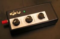
Inside the interrupter. I had to squash everything into one corner of the board to leave room for the pots and switches.
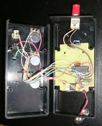
The fiber receiver I used was OPF482, stocked at Digi-Key. It doesn't have a built in amplifier though, I had to add a comparator for that.
David
tesla500, Tue Mar 03 2009, 06:58AM
Thanks Steve!
I was just working on the coil tonight, I added more caps to the MMC to bring it up to 0.544uF 6kV. I also tested it out up to 400VDC bus voltage, no explosions this time
 Arcs reach 1m in length no problem, I now need a bigger space to run it in. I should get that change at Geek Day this weekend.
I also finished a PIC based interrupter. This one has can run the normal repetitive mode, as well as single shot with 1 to 7 bursts. I found that having a several bursts quickly in a row (~1.5-3ms apart) produces long "single shot" sparks, at least twice as long as just 1 burst.
Probably the most professional looking thing I've ever made.

Inside the interrupter. I had to squash everything into one corner of the board to leave room for the pots and switches.

The fiber receiver I used was OPF482, stocked at Digi-Key. It doesn't have a built in amplifier though, I had to add a comparator for that.
David
Re: "MMI 1" - New DRSSTC
GeordieBoy, Tue Mar 03 2009, 11:53AM
Were the tests at 400VDC running from the Active PFC front-end?
If so i'd be interested to know how much the DC bus voltage deviated when you did those "bunch of seven" bursts with the interrupter.
-Richie,
PS. Nice slo-mo video too.
GeordieBoy, Tue Mar 03 2009, 11:53AM
Were the tests at 400VDC running from the Active PFC front-end?
If so i'd be interested to know how much the DC bus voltage deviated when you did those "bunch of seven" bursts with the interrupter.
-Richie,
PS. Nice slo-mo video too.
Re: "MMI 1" - New DRSSTC
tesla500, Tue Mar 03 2009, 08:24PM
The 400V test was using a variac. I'll give the PFC converter a try tonight.
David
tesla500, Tue Mar 03 2009, 08:24PM
The 400V test was using a variac. I'll give the PFC converter a try tonight.
David
Re: "MMI 1" - New DRSSTC
tesla500, Thu Mar 05 2009, 07:18AM
I now have pretty much everything mounted in the coil base, save for the light-bulb-based bus cap discharger. The PFC appears to be working flawlessly. I haven't gotten a chance to measure the bus ripple yet, I need to figure out how to do that safely.
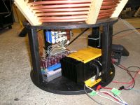
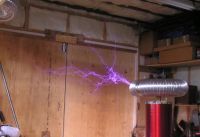
I brought the coil out into the garage and opened up the pulse width a little, performance seemed decent, getting 4.5' arcs while drawing 1kW from the mains. Still need to do some tuning with the new bigger toroid.
Here's the best arc picture I've gotten so far:
David
tesla500, Thu Mar 05 2009, 07:18AM
I now have pretty much everything mounted in the coil base, save for the light-bulb-based bus cap discharger. The PFC appears to be working flawlessly. I haven't gotten a chance to measure the bus ripple yet, I need to figure out how to do that safely.

I brought the coil out into the garage and opened up the pulse width a little, performance seemed decent, getting 4.5' arcs while drawing 1kW from the mains. Still need to do some tuning with the new bigger toroid.
Here's the best arc picture I've gotten so far:

David
Re: "MMI 1" - New DRSSTC
tesla500, Sun Mar 08 2009, 09:25PM
I was finally able to run the coil outside and turn up the power. The ladder is 76" away from the breakout point in the photos below. The coil was pegging the 15A meter during these runs. Burst length was about 80-100uS.
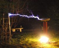
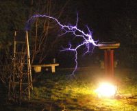
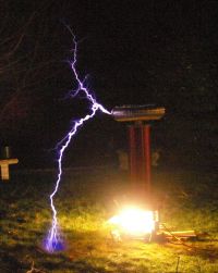
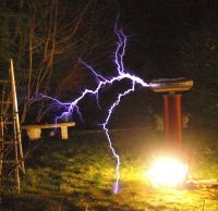
David
tesla500, Sun Mar 08 2009, 09:25PM
I was finally able to run the coil outside and turn up the power. The ladder is 76" away from the breakout point in the photos below. The coil was pegging the 15A meter during these runs. Burst length was about 80-100uS.


David
Re: "MMI 1" - New DRSSTC
Steve Conner, Sun Mar 08 2009, 09:35PM
Ooo, nice! Is that fire coming from the electronics, though?
Steve Conner, Sun Mar 08 2009, 09:35PM
Ooo, nice! Is that fire coming from the electronics, though?
Re: "MMI 1" - New DRSSTC
Alexandre, Sun Mar 08 2009, 10:53PM
Amazing and wonderful sparks...
Alexandre, Sun Mar 08 2009, 10:53PM
Amazing and wonderful sparks...
Re: "MMI 1" - New DRSSTC
tesla500, Mon Mar 09 2009, 01:36AM
Thanks guys!
Nope, that's not fire, it's the bus discharge lightbulbs. I need to paint them black.
David
tesla500, Mon Mar 09 2009, 01:36AM
Thanks guys!
Nope, that's not fire, it's the bus discharge lightbulbs. I need to paint them black.
David
Re: "MMI 1" - New DRSSTC
Dalus, Mon Mar 09 2009, 03:11PM
Very nice results for such a small coil. I'm glad to see that the multiple H-bridge approach works this well. How much current are you running through the primary in this outdoor run?
I'm planning to build a dual CM-300 H-bridge in my new coil. Would be nice to see how well this works with large IGBTs. Going to rebuild my current single H-bridge CM-300 coil for that.
Re: "MMI 1" - New DRSSTC
Tom540, Mon Mar 09 2009, 04:44PM
wow, great results, I'm going to have to give this approach a try. Those IGBT's are the ones I like to use. Cheap fast and no insane lead times.
Tom540, Mon Mar 09 2009, 04:44PM
wow, great results, I'm going to have to give this approach a try. Those IGBT's are the ones I like to use. Cheap fast and no insane lead times.
Re: "MMI 1" - New DRSSTC
tesla500, Mon Mar 09 2009, 11:35PM
The limiter is currently set to 800A, and was being hit quite often during the high power run. I could probably turn it up, the primary cap is safe voltage wise up to about 1.1kA.
David
tesla500, Mon Mar 09 2009, 11:35PM
The limiter is currently set to 800A, and was being hit quite often during the high power run. I could probably turn it up, the primary cap is safe voltage wise up to about 1.1kA.
David
Re: "MMI 1" - New DRSSTC
GeordieBoy, Tue Mar 10 2009, 01:02AM
Nice spark pictures. When you said the line current draw pegged a 15A meter, what was the line voltage? 110V or 230V? ...or more?
> Nope, that's not fire, it's the bus discharge lightbulbs. I need to paint them black.
Or maybe just have them switched in by a relay when the mains power is removed?
Painting them black might cause them to get a little hot!
-Richie,
Re: "MMI 1" - New DRSSTC
tesla500, Tue Mar 10 2009, 06:55AM
The coil was running on 120V with the active PFC when pegging the meter. The wiring run was quite long, about 30m 14AWG total from the panel to the coil. Maybe the draw would have been lower if the line voltage stayed high. With a burst length 1 primary cycle shorter, the draw was about 14A.
I wanted to use a relay for the bus discharge, but I initially discounted it because of the universal input voltage. Actually, now that I think about it, the relay coil could run off the switchmode AC adapter powering the control board.
David
Re: "MMI 1" - New DRSSTC
GeordieBoy, Tue Mar 10 2009, 01:09PM
Thanks for the info. 6ft sparks for 1800watt input sounds like very good performance! Do you know what the spark repetition rate was during those runs?
Regarding the discharge relay, you might be able to power it off an auxilliary winding consisting of a few turns around the core of the boost inductor in the active PFC. If you use a full-wave voltage doubler rectifier it will output a DC voltage which is proportional to the boost voltage at the output of the active PFC converter. Since the boost output is semi-regulated to say 380V, then your auxilliary supply can also be semi-regulated to say 12V for a relay. The active PFC controller chip itself along with cooling fans etc are often powered this way.
The only problem with this might be that the inrush current limiting bits of the supply will also get hit with the inrush to the lamps before the PFC converter starts up, opens the relay and disconnects the lamps.
If it was me, I would replace the lamps and the relay with a few paralleled high-wattage resistors connected directly across the DC bus caps. Relays can fail to operate and filament lamps have been known to fail open circuit, so I'd want something more reliable as a safety device.
-Richie,
Re: "MMI 1" - New DRSSTC
Dalus, Tue Mar 10 2009, 03:27PM

Dalus, Tue Mar 10 2009, 03:27PM
GeordieBoy wrote ...
If it was me, I would replace the lamps and the relay with a few paralleled high-wattage resistors connected directly across the DC bus caps. Relays can fail to operate and filament lamps have been known to fail open circuit, so I'd want something more reliable as a safety device.
-Richie,
I always use a really, they almost never fail and just in case it fails there's a high brightness LED to indicate that there is still energy stored in the capacitor. This way you don't need huge resistors If it was me, I would replace the lamps and the relay with a few paralleled high-wattage resistors connected directly across the DC bus caps. Relays can fail to operate and filament lamps have been known to fail open circuit, so I'd want something more reliable as a safety device.
-Richie,

Print this page