
2.5kJ Capacitor Bank (Complete, finally!)
aonomus, Sat Jan 31 2009, 03:39AMSo I've decided to build a nice big capacitor bank for pulse power experiments, while conventional wisdom says that electrolytic caps aren't up to the job, I'm determined to try otherwise. My plan is to use 38000uF at 450V in electrolytic caps and use a bunch of diodes and SCR's to minimize/eliminate any ringing that would reduce the lifespan or destroy my caps...
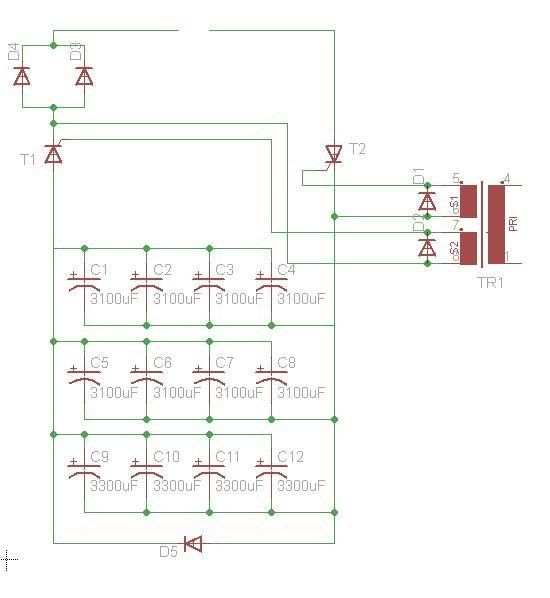
I'm going to use a pair of heavy duty (5.3kA peak stud diodes) placed in-line with the load to eliminate most of the ringing, and on top of that I will use 2 puck SCR's (5.5kA peak), one on the +ve side and one on the -ve side of the cap bank, triggered using a GDT so that I get high-side isolation.

I will use another smaller stud SCR to achieve safe-discharge through 3 or 4 incandescent bulbs incase residual charge remained, or due to a failure in the load. Charging will be done either by a cascade with a variac, or by a big boost converter so I can strap a 12V battery to it and use it away from a source of AC. The charging circuit will be connected/disconnected by a DIY contactor I suppose, because the big spike of current and back EMF would likely destroy a small boost converter, and no doubt cause havoc on a 120VAC line.
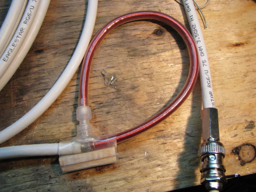
Also, I have built a rogowski coil and I'll build an active integrator so I can measure the current waveform, and I'll capture it with my laptop soundcard with an attenuator.
The overall design will look like this, minus a few parts:
Construction photos:
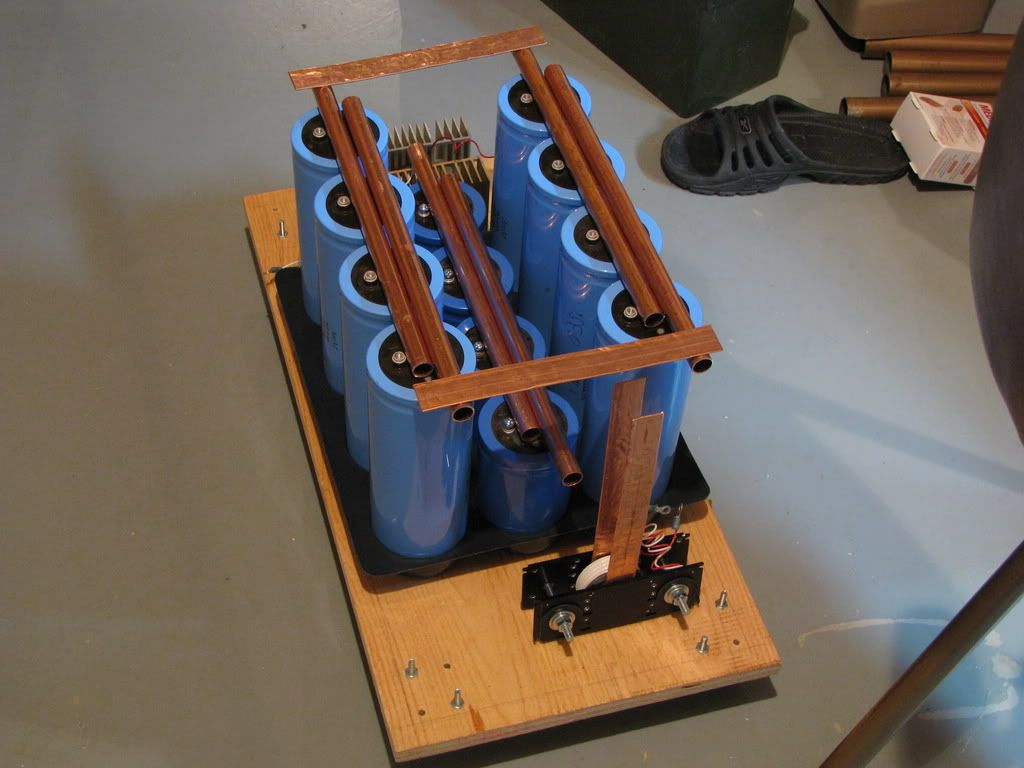
Mockup with unflattened copper pipes, one SCR pictured infront, the other in back. Plywood base with caster wheels, eventually there will be a case with handles for easy transportation.
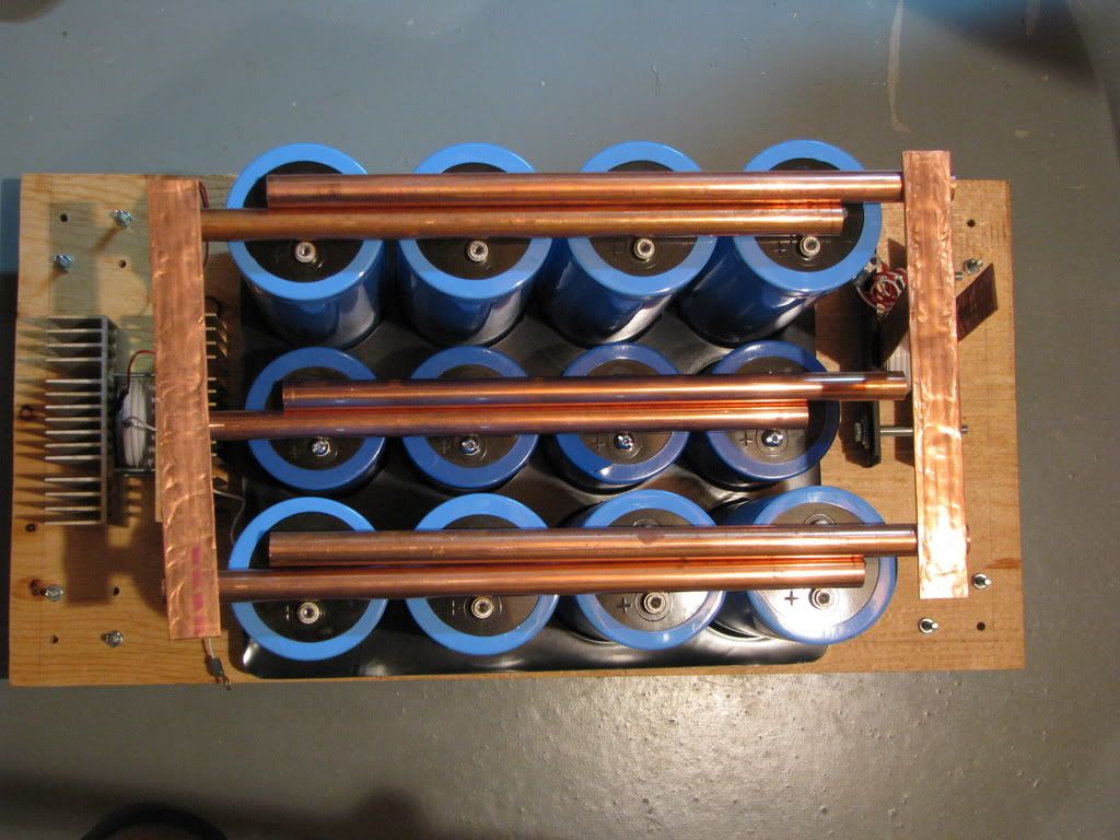
Top-down view of the mockup
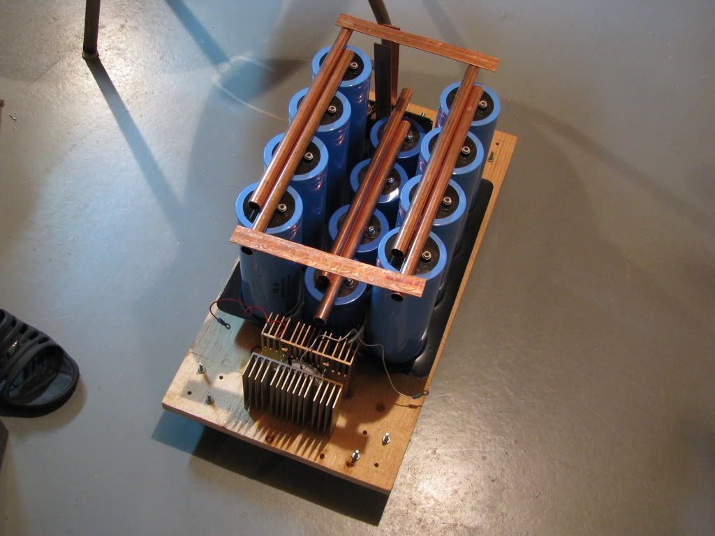
Other side
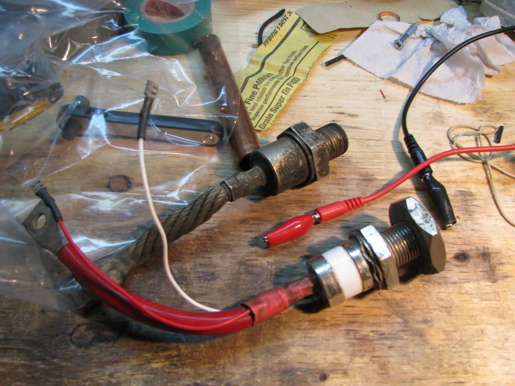
Big diode (in the back) that I'll place across +ve to -ve to get rid of any reverse bias.
So, any thoughts, comments, suggestions?
Re: 2.5kJ Capacitor Bank (Complete, finally!)
Backyard Skunkworks, Sat Jan 31 2009, 03:57AM
Nice. So what kind of peak current are you expecting, and will we see you use these for a coilgun?
Backyard Skunkworks, Sat Jan 31 2009, 03:57AM
Nice. So what kind of peak current are you expecting, and will we see you use these for a coilgun?
Re: 2.5kJ Capacitor Bank (Complete, finally!)
aonomus, Sat Jan 31 2009, 04:03AM
Peak current depends on the inductance of all the connections, and somehow I doubt that the buss-bar layout is optimal, however its still going to be very high, at least 5-10kA. The diodes should ensure that I can safely use inductive loads without back-EMF destroying the caps, which means a coilgun, railgun, can crusher, or even a hdd platter launcher are all possibilities. On the resistive side, I can do wire exploding (or any other mildly conductive object exploding).
Re: 2.5kJ Capacitor Bank (Complete, finally!)
MRacerxdl, Sat Jan 31 2009, 04:27AM
Very Nice! I cant wait to see the complete setup and the results =)
Very good, I was thinking about building one, but the caps are a little expensive here, so I must think before buying :P
MRacerxdl, Sat Jan 31 2009, 04:27AM
Very Nice! I cant wait to see the complete setup and the results =)
Very good, I was thinking about building one, but the caps are a little expensive here, so I must think before buying :P
Re: 2.5kJ Capacitor Bank (Complete, finally!)
big5824, Sat Jan 31 2009, 11:55AM
how flat have you managed to get the copper pipe? Mine still has lots of little bumps in, which I think will give a bad connection.
big5824, Sat Jan 31 2009, 11:55AM
how flat have you managed to get the copper pipe? Mine still has lots of little bumps in, which I think will give a bad connection.
Re: 2.5kJ Capacitor Bank (Complete, finally!)
rp181, Sat Jan 31 2009, 03:59PM
To make copper flat, just hammer it as flat as you can, turn it around and do that again. I also put a big steel block i found outside on it, and hammer that.
rp181, Sat Jan 31 2009, 03:59PM
To make copper flat, just hammer it as flat as you can, turn it around and do that again. I also put a big steel block i found outside on it, and hammer that.
Re: 2.5kJ Capacitor Bank (Complete, finally!)
aonomus, Sat Jan 31 2009, 05:07PM
I've only managed to get it reasonably flat, acceptable for a buss bar, but unacceptable for connecting to a hockey puck SCR. I may have to resort to lapping the end of a piece of copper to get it super smooth.
aonomus, Sat Jan 31 2009, 05:07PM
I've only managed to get it reasonably flat, acceptable for a buss bar, but unacceptable for connecting to a hockey puck SCR. I may have to resort to lapping the end of a piece of copper to get it super smooth.
Re: 2.5kJ Capacitor Bank (Complete, finally!)
rp181, Sat Jan 31 2009, 06:32PM
the tension should flatten it enough.
rp181, Sat Jan 31 2009, 06:32PM
the tension should flatten it enough.
Re: 2.5kJ Capacitor Bank (Complete, finally!)
aonomus, Sun Feb 01 2009, 08:33PM
Ok so a few updates:
1. I've cleaned the big stud diode I got for free with some alcohol and it turns out that its a 1n4047, which unfortunately is only rated for 200V. Instead of this big stud diode, I plan to use 1 or 2 isotop packaged dual diodes rated at 500A surge each (at 800V). It may be a bit overkill, but I sampled these and I have no use for them.
2. I've finished flattening the buss bars, probably some time this week I'll make a jig so I can drill the buss bars evenly and bolt the entire thing together.
3. I've figured out how to mount the other SCR puck, so I'll work on that too.
Unfortunately another bout of discussion on my cap bank says that because I am using diodes in series to block any back-EMF, the work-coil may undergo an extreme voltage spike, akin to a buck converter of sorts... I may have to redistribute the diodes so I have one anti-parallel with the load itself, and one in series. The result of a massive voltage spike would be blowing the puck SCR's and charging the bank in reverse, so I may have to use a resistive load with the anti-parallel diode to solve this. I have a big (100W 3ohm) power resistor which may fit the job.
Re: 2.5kJ Capacitor Bank (Complete, finally!)
aonomus, Wed Feb 04 2009, 03:47AM
Ok today I made a good amount of progress on the cap bank, drilled the buss bars, positioned and mounted the caps and linked up the 3 sets of caps. The center set of capacitors are shorter than the taller 3100uf ones, so I needed to add a wooden platform to support those caps.
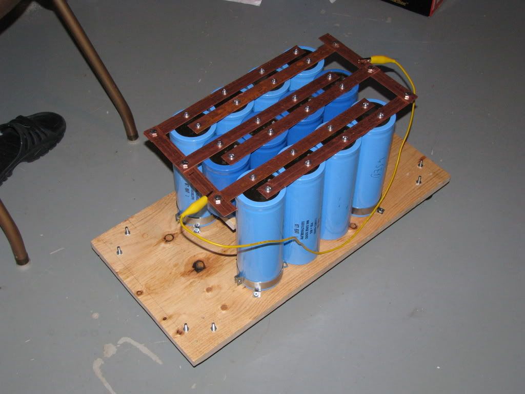
The whole bank currently, note yellow lead, bank was charged up to power and bleed off to test capacitance at low voltage. Yellow lead to short for safety.
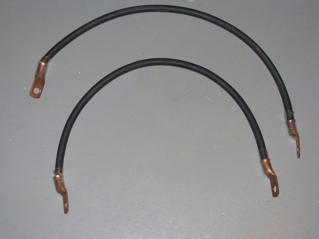
A pair of 1awg welding cables, I could use these to join the bank to the test load when I finish it.
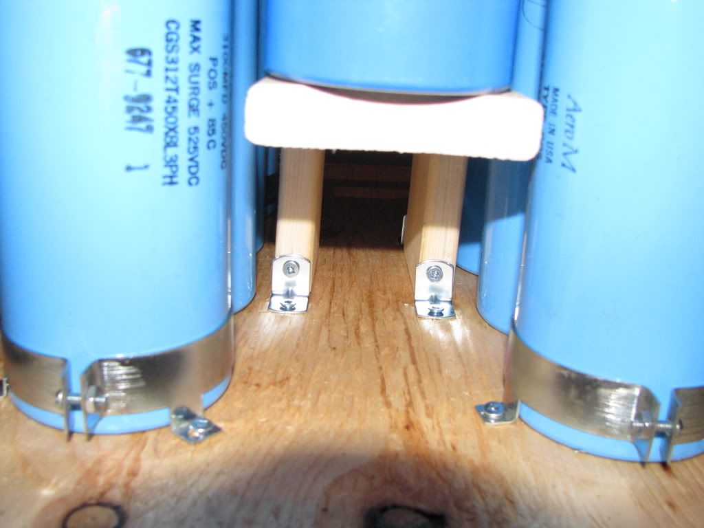
Image of wooden platform underneeth center caps.
aonomus, Wed Feb 04 2009, 03:47AM
Ok today I made a good amount of progress on the cap bank, drilled the buss bars, positioned and mounted the caps and linked up the 3 sets of caps. The center set of capacitors are shorter than the taller 3100uf ones, so I needed to add a wooden platform to support those caps.

The whole bank currently, note yellow lead, bank was charged up to power and bleed off to test capacitance at low voltage. Yellow lead to short for safety.

A pair of 1awg welding cables, I could use these to join the bank to the test load when I finish it.

Image of wooden platform underneeth center caps.
Re: 2.5kJ Capacitor Bank (Complete, finally!)
Mads Barnkob, Wed Feb 04 2009, 02:00PM
Looking good with the new busbars instead of flattened pipe :)
Mads Barnkob, Wed Feb 04 2009, 02:00PM
Looking good with the new busbars instead of flattened pipe :)
Re: 2.5kJ Capacitor Bank (Complete, finally!)
aonomus, Wed Feb 04 2009, 04:50PM
They are flattened pipe...
aonomus, Wed Feb 04 2009, 04:50PM
MadsKaizer wrote ...
Looking good with the new busbars instead of flattened pipe :)
Looking good with the new busbars instead of flattened pipe :)
They are flattened pipe...
Re: 2.5kJ Capacitor Bank (Complete, finally!)
aonomus, Thu Mar 05 2009, 02:05AM
So I got tired of waiting for Fastenall to return my calls on whether or not they ordered my belleville washers (its been 2 weeks, they are no longer getting my business). I have been sitting on these aluminum bars for a while now, so I finally decided to drill the holes and bolt the things together.
Cost of aluminum bars ($3 per bar, 1-1/4" square, 4" long, likely 7075 alloy)
Cost of bolts ($20 for all the hardware!!?!)
Cost of SCRs ($5 a piece)
Making your own SCR clamps (Priceless).
Anyway, onto the pics.

The new and improved clamp, the thing weighs about 750 grams...


For the insulation I decided to use 2 layers of protoboard chopped up and placed between the clamp, and an aluminum flat for contact, with a washer to concentrate pressure in the centre. Just to be safe I oriented the pads on opposite sides (so there is a 2-layer thick portion of fiberglass board to insulate). This was repeated on both sides of the SCR, so the entire clamp itself is floating.
With these 2 clamps done, I will drill holes in the remaining buss bars to bolt the SCR clamps in, I think the entire capacitor bank will be laid out somewhat similar to a NST where the two HV connections come out either side of the box. This will reduce inductance inside the casing, and simplify internal connections.
aonomus, Thu Mar 05 2009, 02:05AM
So I got tired of waiting for Fastenall to return my calls on whether or not they ordered my belleville washers (its been 2 weeks, they are no longer getting my business). I have been sitting on these aluminum bars for a while now, so I finally decided to drill the holes and bolt the things together.
Cost of aluminum bars ($3 per bar, 1-1/4" square, 4" long, likely 7075 alloy)
Cost of bolts ($20 for all the hardware!!?!)
Cost of SCRs ($5 a piece)
Making your own SCR clamps (Priceless).
Anyway, onto the pics.

The new and improved clamp, the thing weighs about 750 grams...


For the insulation I decided to use 2 layers of protoboard chopped up and placed between the clamp, and an aluminum flat for contact, with a washer to concentrate pressure in the centre. Just to be safe I oriented the pads on opposite sides (so there is a 2-layer thick portion of fiberglass board to insulate). This was repeated on both sides of the SCR, so the entire clamp itself is floating.
With these 2 clamps done, I will drill holes in the remaining buss bars to bolt the SCR clamps in, I think the entire capacitor bank will be laid out somewhat similar to a NST where the two HV connections come out either side of the box. This will reduce inductance inside the casing, and simplify internal connections.
Re: 2.5kJ Capacitor Bank (Complete, finally!)
Kolas, Thu Mar 05 2009, 11:47PM
Nice to see you went with the aluminum. It looks great aonomus. Are you planning on soldering those bus bars together? Oh and how about some more pics?
Kolas, Thu Mar 05 2009, 11:47PM
Nice to see you went with the aluminum. It looks great aonomus. Are you planning on soldering those bus bars together? Oh and how about some more pics?
Re: 2.5kJ Capacitor Bank (Complete, finally!)
aonomus, Thu Mar 05 2009, 11:50PM
Worked more on the cap bank today, more pics below.

SCR's mounted with the output terminals test fitted. Cap banks - they give you wings.
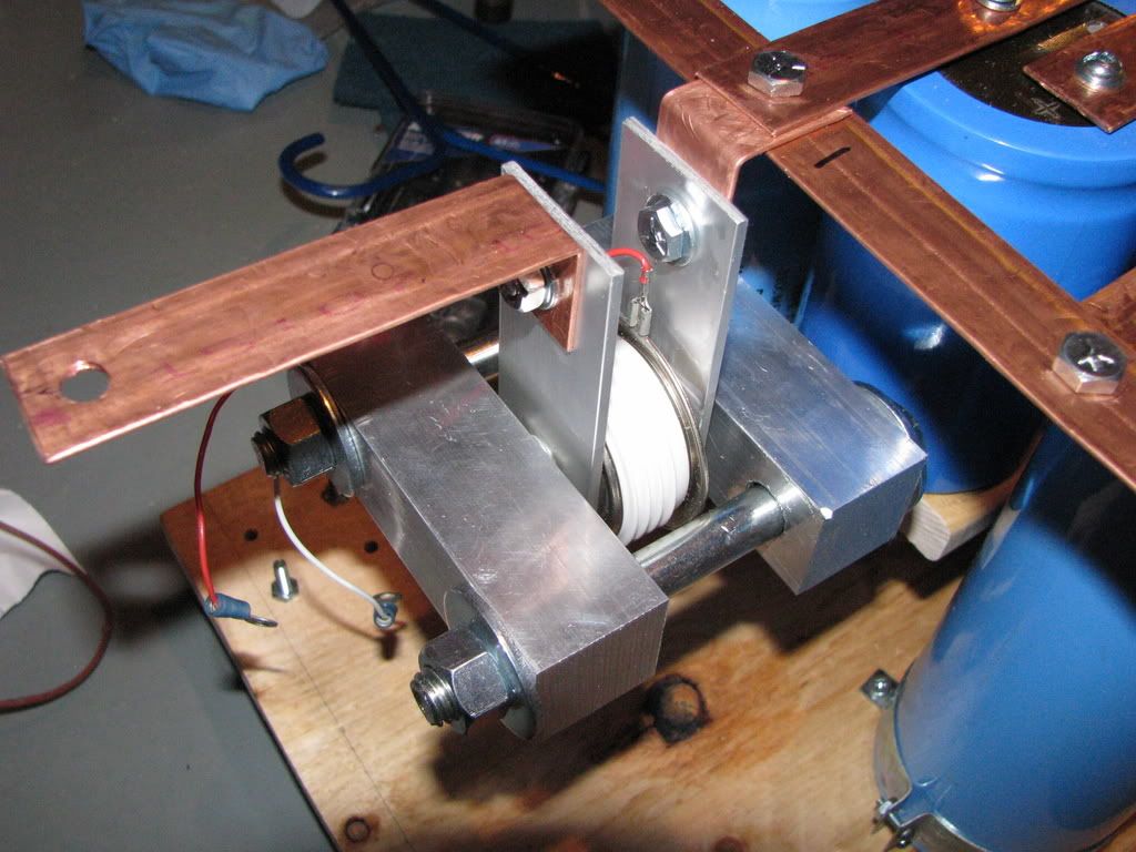
Close-up of the mounting

Test fit of the SCR clamps inside the case: these things just *barely* fit, the clamp on the right side scrapes against the plywood.
aonomus, Thu Mar 05 2009, 11:50PM
Worked more on the cap bank today, more pics below.

SCR's mounted with the output terminals test fitted. Cap banks - they give you wings.

Close-up of the mounting

Test fit of the SCR clamps inside the case: these things just *barely* fit, the clamp on the right side scrapes against the plywood.
Re: 2.5kJ Capacitor Bank (Complete, finally!)
Arcstarter, Fri Mar 06 2009, 01:51AM
:O :O :O :O
Very beautiful!
Looking forward to some stuff being shot and 'sploded.
Also, nice ingenious connections/construction, and the jokes are kool too (purposeful misspelling for the win!) :) :P
Arcstarter, Fri Mar 06 2009, 01:51AM
:O :O :O :O
Very beautiful!
Looking forward to some stuff being shot and 'sploded.
Also, nice ingenious connections/construction, and the jokes are kool too (purposeful misspelling for the win!) :) :P
Re: 2.5kJ Capacitor Bank (Complete, finally!)
..., Fri Mar 06 2009, 03:33AM
That looks awesome!
One comment I might make, you might want to replace the Al bussbars with Cu ones, or at least make sure to star washers at the contacts (I believe you can get ones made out silver or copper for this purpose) to keep the oxidation from the Al from causing problems. I have heard of a few railguns having issues with bad connections to Al bussbars.
Keep up the good work!
Re: 2.5kJ Capacitor Bank (Complete, finally!)
aonomus, Fri Mar 06 2009, 04:29AM
Yea, a few people have been asking me on IRC if I would deal with the contact issues, all the buss bars are only bolted together now, once construction is 100% complete will I sand down the joints, flux, and solder. This is just in case I need to re-measure things and change the configuration (I nearly had to as well since the SCR clamps turned out so huge).
Granted, solder isn't the best option, I suppose some silver solder would do well though?
Edit: late thought of the night
I could unroll some plumbing solder known to contain silver and measure resistance over distance x cross section area in mm^2, and compare to standard Pb/Sn solder... but at the gaps I'm going to fill (sub mm gaps) I don't think its an issue about what type...
Re: 2.5kJ Capacitor Bank (Complete, finally!)
Arcstarter, Sat Mar 07 2009, 11:52PM
Would solder actually work? Pulse discharge seems it would be quite hard on a little bit of solder! We shall see, i suppose.
Arcstarter, Sat Mar 07 2009, 11:52PM
Would solder actually work? Pulse discharge seems it would be quite hard on a little bit of solder! We shall see, i suppose.
Re: 2.5kJ Capacitor Bank (Complete, finally!)
aonomus, Sun Mar 08 2009, 12:00AM
The solder should work since if the joint is properly made, it should fill the contact area voids between buss bars over a 1.5cm x 1.5cm area.
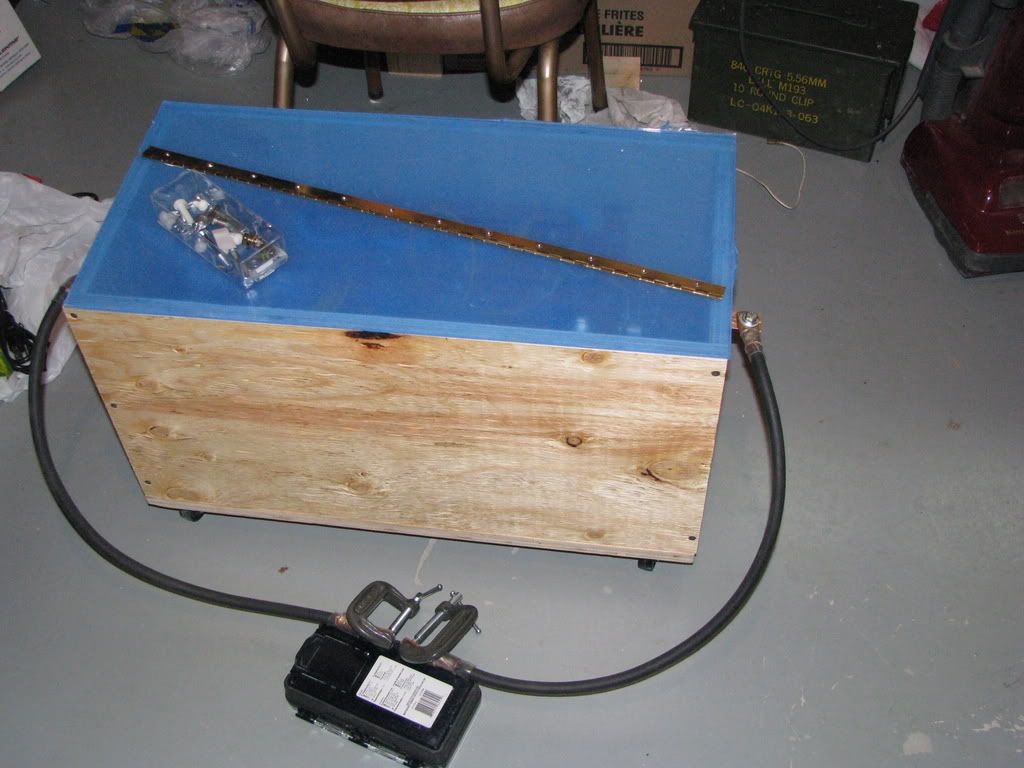
Also, I realized I forgot to mount rp181's gigantic stud diodes, these diodes are going in *series* with the capacitor bank so that they cut down most of the back-EMF to where small diodes (TO-XXX) can handle the remaining pulse. The diodes should also push every bit of energy into the work coil, and then some...
Also, the capacitor bank controls and charger will be mounted on the side of the capacitor bank, I will add a remote trigger so that I don't have to be so close to the bank, at least until I get longer lengths of welding cable (if I can afford them that is).
Anyway, more pics:

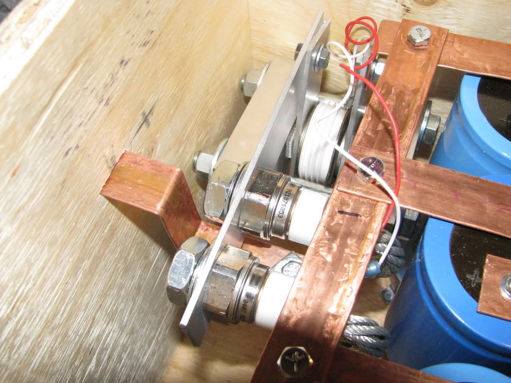
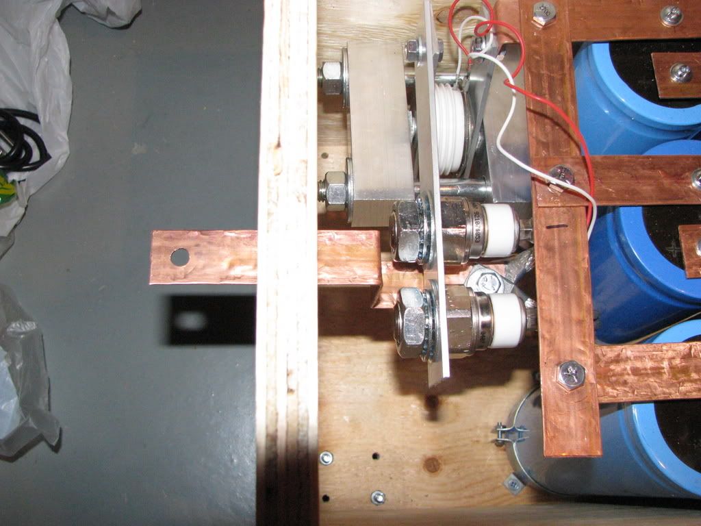
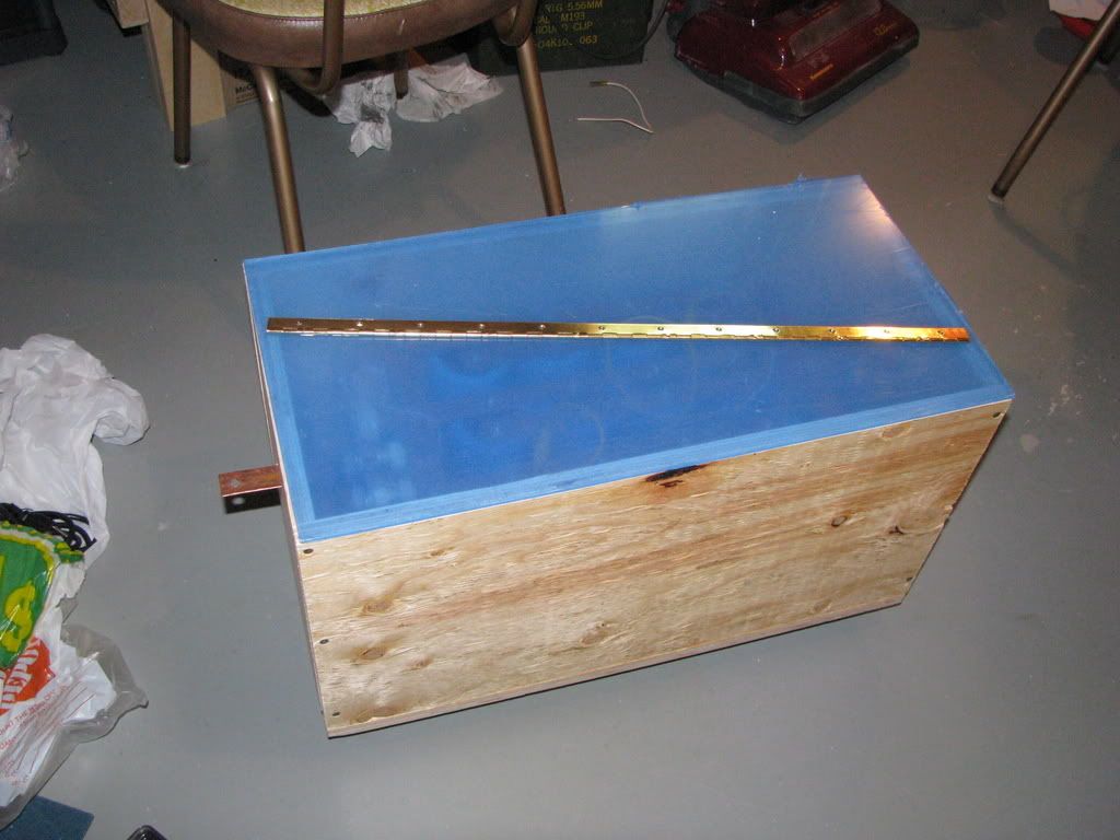
Isn't it so disarmingly benign looking? The blue protective plastic will be removed once I get the acrylic mounted with the hinge, just so I can avoid scratches.
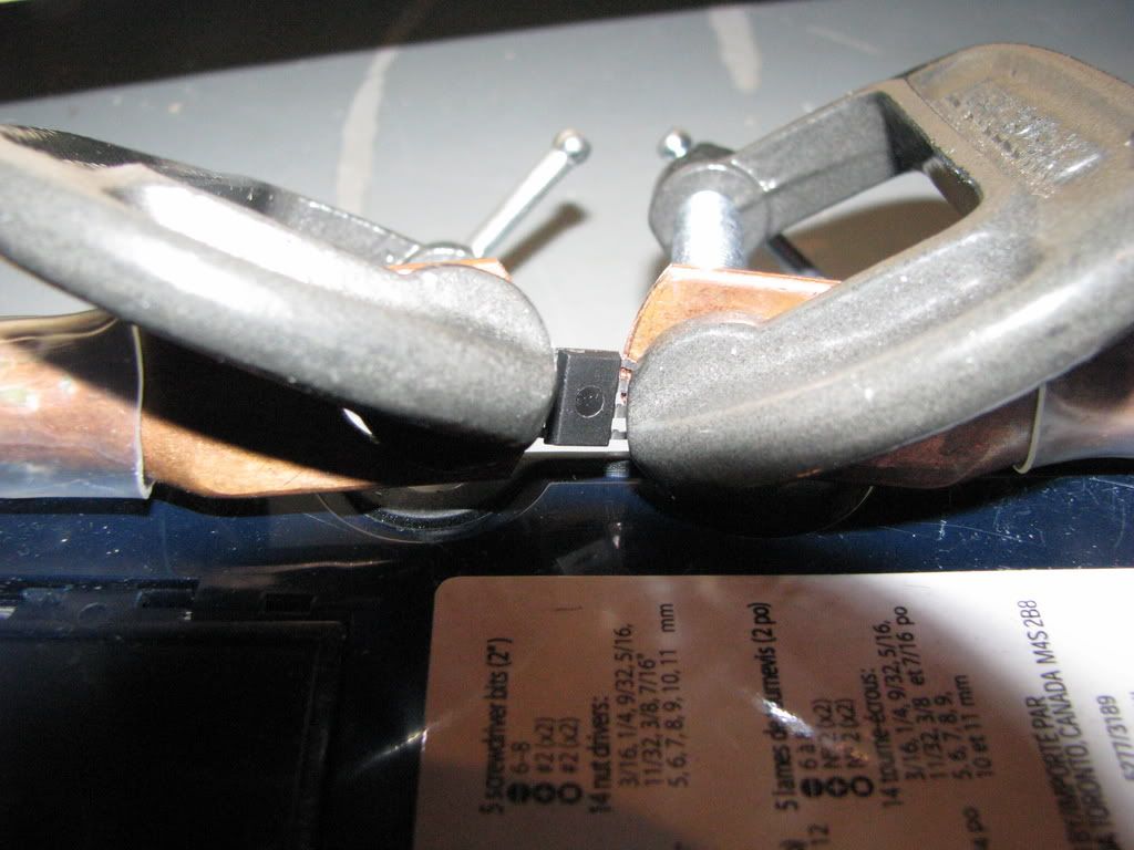
And just to tease you guys :P
aonomus, Sun Mar 08 2009, 12:00AM
The solder should work since if the joint is properly made, it should fill the contact area voids between buss bars over a 1.5cm x 1.5cm area.
Also, I realized I forgot to mount rp181's gigantic stud diodes, these diodes are going in *series* with the capacitor bank so that they cut down most of the back-EMF to where small diodes (TO-XXX) can handle the remaining pulse. The diodes should also push every bit of energy into the work coil, and then some...
Also, the capacitor bank controls and charger will be mounted on the side of the capacitor bank, I will add a remote trigger so that I don't have to be so close to the bank, at least until I get longer lengths of welding cable (if I can afford them that is).
Anyway, more pics:


Isn't it so disarmingly benign looking? The blue protective plastic will be removed once I get the acrylic mounted with the hinge, just so I can avoid scratches.
And just to tease you guys :P


Re: 2.5kJ Capacitor Bank (Complete, finally!)
KLH, Mon Mar 09 2009, 05:45AM
Very nice work. I never thought of using copper pipes as bus bars ; looks like I'll be using that for my coilgun.
The arrangement of your bus bars is good; in fact, that is the recommended arrangement for equal current distribution among all of the capacitors, as specified in a capacitor application note.
Keep up the good work! I can't wait to see how well this will perform.
KLH, Mon Mar 09 2009, 05:45AM
Very nice work. I never thought of using copper pipes as bus bars
 ; looks like I'll be using that for my coilgun.
The arrangement of your bus bars is good; in fact, that is the recommended arrangement for equal current distribution among all of the capacitors, as specified in a capacitor application note.
Keep up the good work! I can't wait to see how well this will perform.
Re: 2.5kJ Capacitor Bank (Complete, finally!)
rp181, Mon Mar 09 2009, 12:19PM
You make the diodes look so much better from when i mounted them... On those diodes, tighten them as much as you can, the toothed washers are more effective than.
Nice job
rp181, Mon Mar 09 2009, 12:19PM
You make the diodes look so much better from when i mounted them... On those diodes, tighten them as much as you can, the toothed washers are more effective than.
Nice job
Re: 2.5kJ Capacitor Bank (Complete, finally!)
Steve Conner, Mon Mar 09 2009, 12:42PM
Am I the only one who can't see what earthly good diodes in series with the load will do?
By the physics of RLC circuits, the current doesn't reverse until after the capacitor voltage has reversed and got as far negative as it's going to. So your capacitors and anti-parallel diodes are already blown by this point.
Re: 2.5kJ Capacitor Bank (Complete, finally!)
Dennis Rogers, Mon Mar 09 2009, 01:48PM
Just another point of concern is using pipe for bus bars. Copper pipe is made from recycled copper. The recycling process leaves way to much impurity to make new electrical conductors. This may show up when you have large amps moving. I'm not saying it's not worth a shot, just be careful.
Re: 2.5kJ Capacitor Bank (Complete, finally!)
aonomus, Mon Mar 09 2009, 05:22PM
Well there are SCR's on both the +ve and -ve side of the capacitors, and the diodes increase the total standoff voltage. Once the capacitors discharge through a inductive load, the inductor causes the voltage reversal. If there are that many diodes to block voltage reversal (2 scrs in series and 1 'big' diode), should there be little reverse biasing of the capacitors?
The simulation said it would work at least....
Re: 2.5kJ Capacitor Bank (Complete, finally!)
KLH, Mon Mar 09 2009, 06:43PM
Steve McConner made an important point. Inductors, when charged with energy, are current sources. They will increase the voltage across themselves until there is an available current path (theoretically to infinity). This means the inductive load will automatically increase its voltage until it is enough to blow thorugh all of your SCRs and diodes. Then it will go to your capacitors and... the rest is self-explanatory (a.k.a. expensive). Instead, you should put the diodes in anti-parallel with the inductive load and place a resistor in series with the diode so that the voltage spike resulting from inductor peak current does not exceed the total reverse breakdown of your SCRs (V = I * R).
KLH, Mon Mar 09 2009, 06:43PM
aonomus wrote ...
Well there are SCR's on both the +ve and -ve side of the capacitors, and the diodes increase the total standoff voltage. Once the capacitors discharge through a inductive load, the inductor causes the voltage reversal. If there are that many diodes to block voltage reversal (2 scrs in series and 1 'big' diode), should there be little reverse biasing of the capacitors?
The simulation said it would work at least....
Steve McConner made an important point. Inductors, when charged with energy, are current sources. They will increase the voltage across themselves until there is an available current path (theoretically to infinity). This means the inductive load will automatically increase its voltage until it is enough to blow thorugh all of your SCRs and diodes. Then it will go to your capacitors and... the rest is self-explanatory (a.k.a. expensive). Instead, you should put the diodes in anti-parallel with the inductive load and place a resistor in series with the diode so that the voltage spike resulting from inductor peak current does not exceed the total reverse breakdown of your SCRs (V = I * R).
Re: 2.5kJ Capacitor Bank (Complete, finally!)
aonomus, Wed Jul 01 2009, 09:04PM
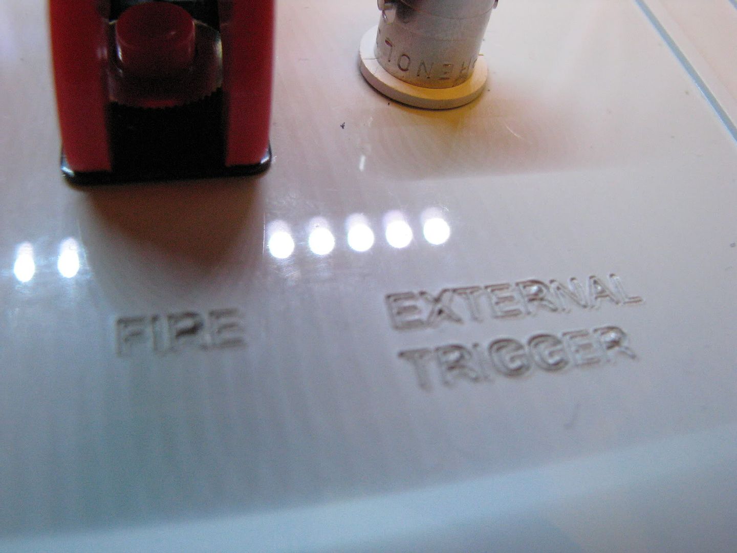
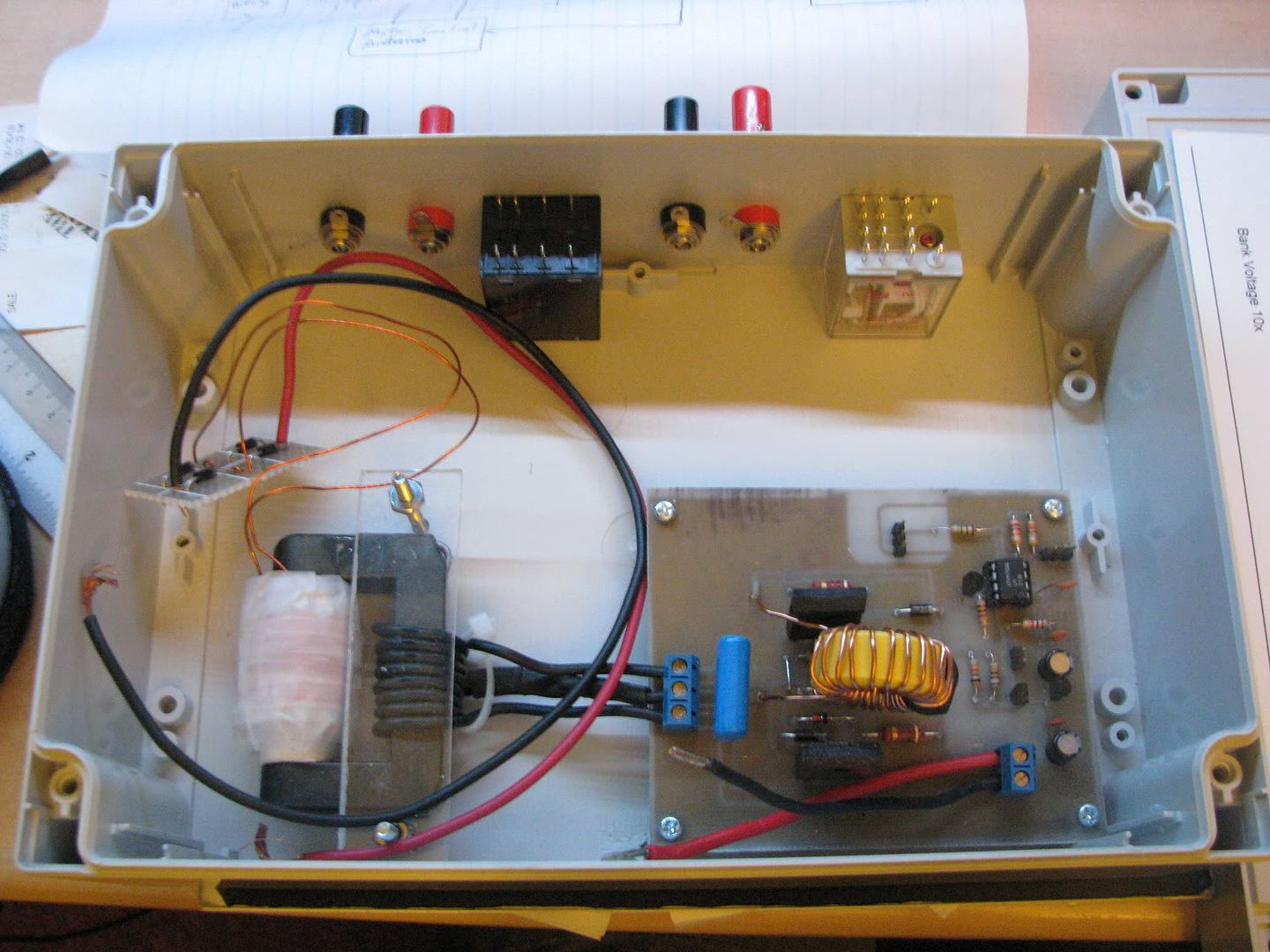
So I finally got some traction on this project again... yesterday I had the capacitor bank charger/control system panel laser-cut from a really heavy duty ABS case (1/4" thick, IP66 rated, it was not fun to cut). The capacitor bank charger was based off of Uzzors ZVS driver with a few tweaks mainly for voltage control and voltage reference. the only remaining building for the charger would be wiring up the relays to control the charger.
On the capacitor bank side, I have reconfigured the SCRs in parallel, but I still have to mount the diodes and then solder all the bus bars together.
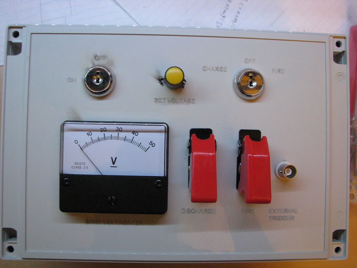
Note: the slight amount of burning was due to the laser being set too high, but a little soap/water will clean that char right off.
aonomus, Wed Jul 01 2009, 09:04PM
So I finally got some traction on this project again... yesterday I had the capacitor bank charger/control system panel laser-cut from a really heavy duty ABS case (1/4" thick, IP66 rated, it was not fun to cut). The capacitor bank charger was based off of Uzzors ZVS driver with a few tweaks mainly for voltage control and voltage reference. the only remaining building for the charger would be wiring up the relays to control the charger.
On the capacitor bank side, I have reconfigured the SCRs in parallel, but I still have to mount the diodes and then solder all the bus bars together.

Note: the slight amount of burning was due to the laser being set too high, but a little soap/water will clean that char right off.


Re: 2.5kJ Capacitor Bank (Complete, finally!)
aonomus, Sun Jul 05 2009, 01:00AM
First charging test video:
To do:
Mount back-emf diode
Mount discharge SCR and load (light bulbs)
Tidy up connectors for charging/control
Test with inductive loads
aonomus, Sun Jul 05 2009, 01:00AM
First charging test video:

To do:
Mount back-emf diode
Mount discharge SCR and load (light bulbs)
Tidy up connectors for charging/control
Test with inductive loads
Re: 2.5kJ Capacitor Bank (Complete, finally!)
aonomus, Thu Jul 09 2009, 09:26PM
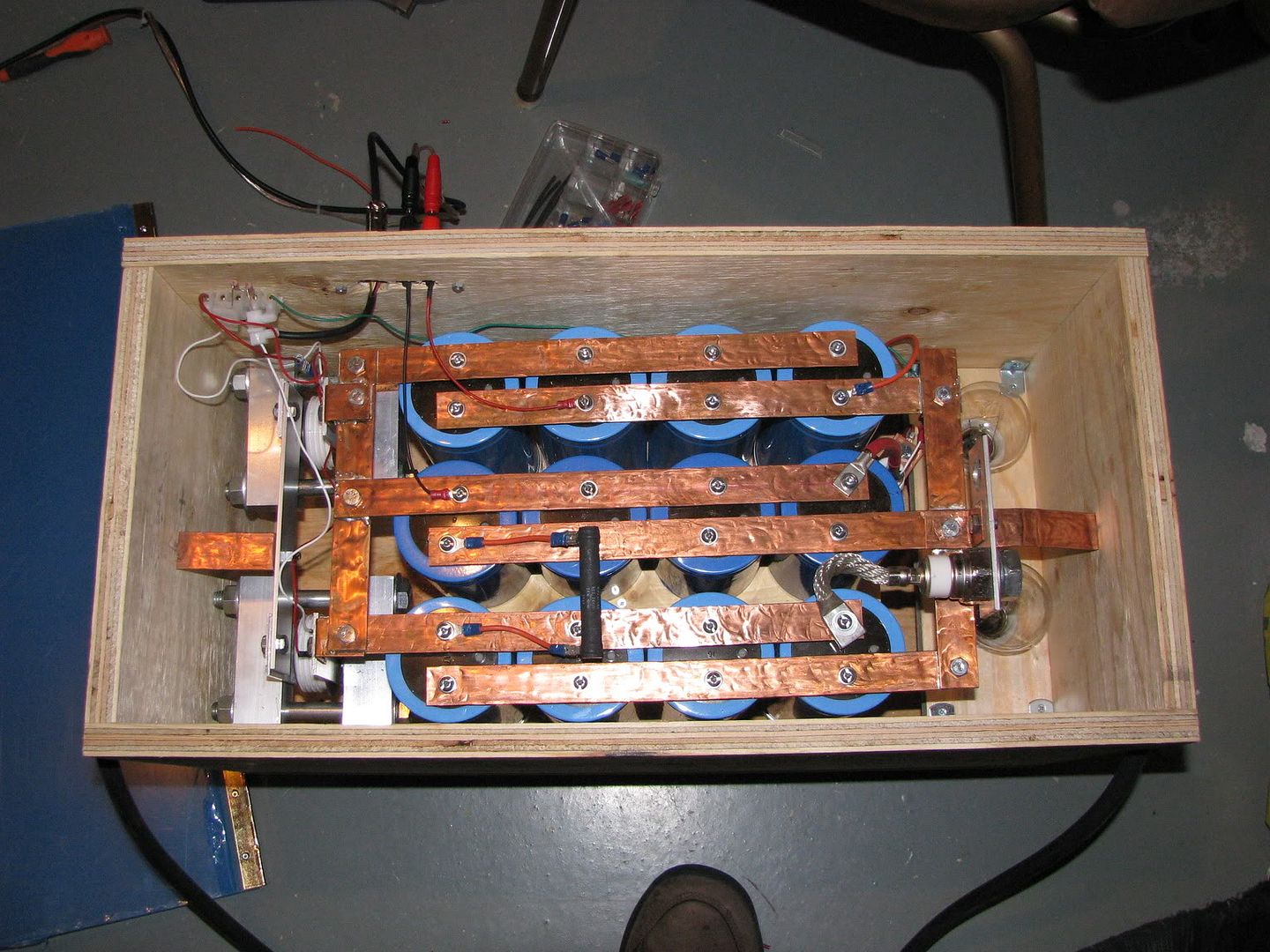
So over the last 2 days I've worked to get this project finished finally. All the bus bars are soldered, connections tightened, discharge load mounted and connected to SCR.
I had some fun doing low power tests, right up until I exploded some wire at 25% power.
Videos:
Testing at low power for can crushing and ring launching:
Slow motion of the last test that left my ears ringing:
aonomus, Thu Jul 09 2009, 09:26PM
So over the last 2 days I've worked to get this project finished finally. All the bus bars are soldered, connections tightened, discharge load mounted and connected to SCR.

I had some fun doing low power tests, right up until I exploded some wire at 25% power.
Videos:
Testing at low power for can crushing and ring launching:

Slow motion of the last test that left my ears ringing:

Re: 2.5kJ Capacitor Bank (Complete, finally!)
aonomus, Mon Jul 13 2009, 12:44AM
Full writeup is here:
aonomus, Mon Jul 13 2009, 12:44AM
Full writeup is here:

Re: 2.5kJ Capacitor Bank (Complete, finally!)
uzzors2k, Mon Jul 27 2009, 08:31AM
You did an awesome job at putting this bank together, very neat an tidy! How did the can crush turn out, you couldn't really see the after-effects in the video.
uzzors2k, Mon Jul 27 2009, 08:31AM
You did an awesome job at putting this bank together, very neat an tidy! How did the can crush turn out, you couldn't really see the after-effects in the video.
Re: 2.5kJ Capacitor Bank (Complete, finally!)
aonomus, Mon Jul 27 2009, 04:03PM
The can crush was minimal, but it was also under 25% power too. I need to take this thing outdoors before I open it up all the way...
aonomus, Mon Jul 27 2009, 04:03PM
The can crush was minimal, but it was also under 25% power too. I need to take this thing outdoors before I open it up all the way...
Print this page