
Uzzors' Coolidge X-ray Machine
uzzors2k, Fri Jan 30 2009, 07:46PMIt's about time I tried using a Coolidge X-ray tube I bought on Ebay last summer. I was given no information on it other than it's a dentist tube, so everything will need to be determined empirically. The x-ray tube is 30cm long and 6cm in diameter. The filament has a resistance of about 0.2 - 0.3 Ohms, and is wound "Benson" style, or as a helical coil. So where do I start? I'll need to know an approximate power rating of the tube, and maximum voltage. Since the x-ray intensity is proportional to the filament temperature, I thought I could measure the anode current at very low filament temps, and assuming the anode current rises linearly with filament current plot a graph. A suitable filament current range can then be determined.
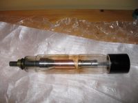
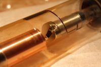
I don't even have ballpark figures for this tube, so your guess is as good as mine! Tube power and tube voltage.
Re: Uzzors' Coolidge X-ray Machine
Download, Fri Jan 30 2009, 10:38PM
So it's got no numbers or markings at all?
Download, Fri Jan 30 2009, 10:38PM
So it's got no numbers or markings at all?
Re: Uzzors' Coolidge X-ray Machine
uzzors2k, Fri Jan 30 2009, 10:59PM
Whoops, thanks for the reminder.
It says:
Ritter
CYB
Made in USA
There's also a serial number stamped on the anode: F35182.
uzzors2k, Fri Jan 30 2009, 10:59PM
Whoops, thanks for the reminder.
It says:
Ritter
CYB
Made in USA
There's also a serial number stamped on the anode: F35182.
Re: Uzzors' Coolidge X-ray Machine
rp181, Fri Jan 30 2009, 11:44PM
You can try emailing the company, or finding a similar sized tube.
Also, congratulations on the 1k post =)
rp181, Fri Jan 30 2009, 11:44PM
You can try emailing the company, or finding a similar sized tube.
Also, congratulations on the 1k post =)
Re: Uzzors' Coolidge X-ray Machine
Proud Mary, Sat Jan 31 2009, 01:43AM
Dental X-ray tubes almost always have anode voltages in the range 50kV - 80kV (with 70kV being much the most common) and anode currents of 5 - 10mA, with 10mA being the most common.
Remember that dental X-ray tubes are designed for short exposures - e.g. 1/15th second - and so will rapidly overheat and destroy themselves if run for any length of time at full power.
Re: Uzzors' Coolidge X-ray Machine
uzzors2k, Sun Feb 01 2009, 07:43PM
Thanks for the tips. I sent an email to some Ritter repairman, so I'll see if I get an answer. For future refernece, I found some info here on using coolidge tubes of unknown ratings.
W007! 1000 posts!
uzzors2k, Sun Feb 01 2009, 07:43PM
Thanks for the tips. I sent an email to some Ritter repairman, so I'll see if I get an answer. For future refernece, I found some info here on using coolidge tubes of unknown ratings.

W007! 1000 posts!
Re: Uzzors' Coolidge X-ray Machine
c4r0, Sun Feb 01 2009, 09:23PM
Hello! Take a look at these tubes:
  Maybe you will find one that looks similar to yours - if it looks similar it should have similar parameters too. You can find also some useful characteristics on that site, and a FAQ section with explanations what each parameter of a tube means:
c4r0, Sun Feb 01 2009, 09:23PM
Hello!
 Take a look at these tubes:
  Maybe you will find one that looks similar to yours - if it looks similar it should have similar parameters too. You can find also some useful characteristics on that site, and a FAQ section with explanations what each parameter of a tube means:
Harry wrote ...
Remember that dental X-ray tubes are designed for short exposures - e.g. 1/15th second
I've had a broken Orix-70 dental x-ray machine and the control unit had exposure time settings up to 3s or so. But maybe such long times was available only at lower anode current settings, i don't know.Remember that dental X-ray tubes are designed for short exposures - e.g. 1/15th second
Re: Uzzors' Coolidge X-ray Machine
Proud Mary, Mon Feb 02 2009, 02:28AM
The reason dental X-ray tubes have very standard ratings is because of the type of work they do - the amount of radiation that must be absorbed by teeth to produce an image is very standard, as are the legal amount of radiation that may be absorbed by the patient, so you won't find much variation from tube to tube.
Assume that the tube is intended to operate at 70kV/5-10mA and you won't be far wrong.
Do you have the RadPro radiation safety freeware calculator, Uzzors? This will calculate the dose in Sieverts for a given tube at a given range, and the amount of radiation shielding required and so on.

If you choose the X-ray menu, you can enter 70kV anode volts, and see how increasing the current increases the dose at any given distance, how filters of different metals will reduce it, and how different shielding materials will attenuate the rays.
Proud Mary, Mon Feb 02 2009, 02:28AM
The reason dental X-ray tubes have very standard ratings is because of the type of work they do - the amount of radiation that must be absorbed by teeth to produce an image is very standard, as are the legal amount of radiation that may be absorbed by the patient, so you won't find much variation from tube to tube.
Assume that the tube is intended to operate at 70kV/5-10mA and you won't be far wrong.
Do you have the RadPro radiation safety freeware calculator, Uzzors? This will calculate the dose in Sieverts for a given tube at a given range, and the amount of radiation shielding required and so on.

If you choose the X-ray menu, you can enter 70kV anode volts, and see how increasing the current increases the dose at any given distance, how filters of different metals will reduce it, and how different shielding materials will attenuate the rays.
Re: Uzzors' Coolidge X-ray Machine
uzzors2k, Mon Feb 02 2009, 07:36PM
I'll run the tube at low current (1mA range), since I'll be using photo-paper anyway. It will make controlling the exposure time much easier too. I've made a shield calculator using mass attenuation coefficients, so I can use the data at physics.nist.gov. My spreadsheet gives the I/I0 factor, and I have a list of radiation doses so I know what the safe range is. All I need to know is the worst (best ) case output from the tube. Does 30-100mSv/hr sound reasonable for a dental x-ray? I found some numbers for x-ray exposure related to medical x-rays, and the average dental x-ray dose is 0.1mSv, per image I assume. Currently I've finished epoxying MOT laminations together into two 3-4cm thick slabs, I'll make exact measurements when the epoxy dries. They should provide more than adequate shielding for 70keV x-rays, and with some distance I'll be safe from backscatter which I doubt is a problem with such low energy.
I have a copy of RadPro, but I'm not sure what some of the inputs mean. Is distance the distance from a pin-point x-ray source to the subject? When I put a tiny number in for the distance the radiation dose is in the order of 1*10^70 mSv/hr! Is that true? It seems the dose approaches an infinite value as the distance approaches 0, regardless of voltage/current. Is the shield placed at the tube or at the subject, or does it matter?
Oh well, assuming 100 mSv/hr exposure rate, and a 3cm iron shield providing near 180 degree protection, the radiation will be well below background radiation levels.
uzzors2k, Mon Feb 02 2009, 07:36PM
I'll run the tube at low current (1mA range), since I'll be using photo-paper anyway. It will make controlling the exposure time much easier too. I've made a shield calculator using mass attenuation coefficients, so I can use the data at physics.nist.gov. My spreadsheet gives the I/I0 factor, and I have a list of radiation doses so I know what the safe range is. All I need to know is the worst (best
 ) case output from the tube. Does 30-100mSv/hr sound reasonable for a dental x-ray? I found some numbers for x-ray exposure related to medical x-rays, and the average dental x-ray dose is 0.1mSv, per image I assume. Currently I've finished epoxying MOT laminations together into two 3-4cm thick slabs, I'll make exact measurements when the epoxy dries. They should provide more than adequate shielding for 70keV x-rays, and with some distance I'll be safe from backscatter which I doubt is a problem with such low energy.
I have a copy of RadPro, but I'm not sure what some of the inputs mean. Is distance the distance from a pin-point x-ray source to the subject? When I put a tiny number in for the distance the radiation dose is in the order of 1*10^70 mSv/hr! Is that true? It seems the dose approaches an infinite value as the distance approaches 0, regardless of voltage/current. Is the shield placed at the tube or at the subject, or does it matter?
Oh well, assuming 100 mSv/hr exposure rate, and a 3cm iron shield providing near 180 degree protection, the radiation will be well below background radiation levels.
Re: Uzzors' Coolidge X-ray Machine
Proud Mary, Tue Feb 03 2009, 01:36AM
RadPro is a well-accepted practical dosimetry application, so does not concern itself with theoretical pin-point sources and infinite numbers.
If you enter 70kV anode voltage and 1mA current, you can rely on RadPro's distance, filter, and shield calculations for all practical purposes with a real world tube such as yours - and see how very few seconds it takes for you to absorb a hazardous dose if you expose your body to the rays at short distances, as I am sure you know.
As for the size of your anode spot, you may image it easily enough by making your own X-ray pinhole camera, if you have what it takes to drill very small diameter holes in a metal sheet. There is a lot about X-ray pin hole cameras on the web to guide you.
Post Script: the best way to control the anode current is by having a variable heater voltage.
Re: Uzzors' Coolidge X-ray Machine
uzzors2k, Tue Feb 03 2009, 09:53PM
I received a response from the Ritter guy, and Harry your assumptions are almost dead-on. Apparently this tube type has been around since 1957, I wonder how old mine is. It certainly doesn't look very worn.


uzzors2k, Tue Feb 03 2009, 09:53PM
I received a response from the Ritter guy, and Harry your assumptions are almost dead-on. Apparently this tube type has been around since 1957, I wonder how old mine is. It certainly doesn't look very worn.


Re: Uzzors' Coolidge X-ray Machine
Proud Mary, Wed Feb 04 2009, 02:14AM
Uzzors, I think you can be sure that the recommendation not to use filters to cut out soft X-rays would not be permitted nowadays. Trying putting the filters in and out on RadPro with 70KVP/10mA at a distance of 1 cm (inside your mouth!) and see how much difference it makes to the absorbed dose. Radiological safety criteria have changed very much in the last 50 years!
You should consider the possibility that your tube was removed from service because its emission began to fall below the level needed for dental X-ray service - which is not to suggest that it is dead - far from it.
I would suggest you try out this tube in a clear container of oil, to prevent flash-over along the glass surface, and so that you can see any glass fluorescence, and the presence of any glowing plasma which might suggest that the tube had gone "soft" (i.e. lost some vacuum). Start with microamperes only and only increase current very slowly. Watch the work in a mirror so you can see what you are doing, without the hazard of direct line-of-sight exposure. (though some of the rays are, of course, scattered, reflected and refracted from the background)
A GM tube is not suitable (ikke!) for measurments with this kind of apparatus, except for telling you that radiation is either present or is not present. You must make an ionization chamber - (the parallel plate type being much the easiest to make in the home workshop) to know how many Grays you have.
If you need help with the ionization chamber, just ask.
Proud Mary, Wed Feb 04 2009, 02:14AM
Uzzors, I think you can be sure that the recommendation not to use filters to cut out soft X-rays would not be permitted nowadays. Trying putting the filters in and out on RadPro with 70KVP/10mA at a distance of 1 cm (inside your mouth!) and see how much difference it makes to the absorbed dose. Radiological safety criteria have changed very much in the last 50 years!

You should consider the possibility that your tube was removed from service because its emission began to fall below the level needed for dental X-ray service - which is not to suggest that it is dead - far from it.
I would suggest you try out this tube in a clear container of oil, to prevent flash-over along the glass surface, and so that you can see any glass fluorescence, and the presence of any glowing plasma which might suggest that the tube had gone "soft" (i.e. lost some vacuum). Start with microamperes only and only increase current very slowly. Watch the work in a mirror so you can see what you are doing, without the hazard of direct line-of-sight exposure. (though some of the rays are, of course, scattered, reflected and refracted from the background)
A GM tube is not suitable (ikke!) for measurments with this kind of apparatus, except for telling you that radiation is either present or is not present. You must make an ionization chamber - (the parallel plate type being much the easiest to make in the home workshop) to know how many Grays you have.
If you need help with the ionization chamber, just ask.

Re: Uzzors' Coolidge X-ray Machine
usaman65, Tue Feb 10 2009, 07:10PM
Are you intending on using that? better have some good sheilding ans a geiger counter or an ion chamber survey meter because of such high REntogens.
kev
usaman65, Tue Feb 10 2009, 07:10PM
Are you intending on using that? better have some good sheilding ans a geiger counter or an ion chamber survey meter because of such high REntogens.
kev
Re: Uzzors' Coolidge X-ray Machine
uzzors2k, Thu Feb 19 2009, 11:38AM
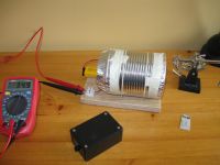
Hehe, picking up some Norwegian, Harry? I completed improved tin can ionization chamber as shown here. It works fairly well with background radiation reading ca. 20mV, and the radium watch-hands Leslie gave me read ca. 170mV when they're close to the chamber window. With the watch hands a few centimeters distance the reading drops to 70mV. This chamber is much more useful than the Geiger counter I constructed, and only cost about 1£. Do you think it would be worth the trouble to roughly calibrate it? I was thinking of acquiring a few samples of mineral with known intensity, and plot the voltage/radiation in a graph. Or is it even reasonable to expect the chamber to be linear enough?

Re: Uzzors' Coolidge X-ray Machine
Proud Mary, Thu Feb 19 2009, 01:15PM
Erik, you can make some very basic linearity tests by placing your source on a measuring ruler, and taking a reading off your meter for every 5mm, or 10mm, that you move the source away. Then you can plot this on a graph, and see what sort of graph you have. Calculation will be easier if you have a non-directional source - an isotropic radiator.
You can use the same method for drawing graphs of directional sensitivity.
This basic apparatus with be affected by temperature, pressure, supply voltage, and perhaps capacitance to your hand, and other local objects.
But it is still much better than a GM tube.
You could calibrate it with a gamma source of known intensity, but you can also calibrate it roughly against your tube anode voltage, if you can measure and vary this.
The properties of metal filters (i.e. aluminium) can also be used as an aid to calibration (see RadPro)
And you can, of course, go back to the primary definition of One Roentgen, and start with the volume of your chamber, the voltage applied, and the current that flows, if you have the means to measure accurately very tiny currents.
Re: Uzzors' Coolidge X-ray Machine
uzzors2k, Fri Feb 27 2009, 11:59PM
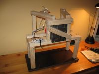
I've made a basic x-ray machine, with a tube holder, filament current controller and shield. I'll add more details later, but I need to sleep now. My question is; how hot is the filament supposed to be? I've got an intensifier screen, some CRT dust and a glow-in-the-dark toy under the tube and none show signs of excitation. Currently I've run the filament from barely dull red to glowing yellow. Does it have to get bright white before it starts working? My multimeter goes nuts when I attempt to measure tube current which is unfortunate. I'll try again tomorrow.

Re: Uzzors' Coolidge X-ray Machine
Proud Mary, Sat Feb 28 2009, 12:37AM
Erik, none of those methods will show much to the naked eye.
What about your ionization chamber? If you know for sure that chamber works from using it with other sources, then if it does not show any indication I would suggest no X-rays are being emitted.
Is your anode voltage holding up when your apply heater voltage? If you have no way of measuring it, I will send you 5 x 200M 2W HV resistors so you can make a HV potential divider, if you haven't got any yourself.
You must NEVER apply anode voltage to an X-ray tube - or any other power thermionic tube - before the heater is properly hot - 3 minutes to be very safe, or the tube may be seriously dsmaged.
The right colour for the heater would be bright yellow to yellow-white, but you must only turn it up if you can watch the anode current, or at least the voltage across the tube.
Are you sure your PSU can give out 7mA @ 70kV without falling flat as the heater comes on and the tube starts to draw current?
Set up some good tests with the ionization chamber - including a test with, and without, a shield - and make sure the HV ions around the machine can't directly interfere with the chamber. ( f.eks. put it under a kitchen sieve connected to Earth)
Then we'll see what happens next, Erik.

Re: Uzzors' Coolidge X-ray Machine
uzzors2k, Sat Feb 28 2009, 04:09PM
My ionization chamber became desensitized after the very first test. I had it directly under the tube thinking it was shielded from HV ions with all the tin-foil, which it wasn't. The reading is now -30mV with just background radiation and just 12mV with the radium watch-hands VS 30mV background and 300mV watch-hands before. I assume the pA-sensing Darlington has suffered, I'll replace it later. Either way, before the first tests I was unsure of it's practical use since it takes so long for the reading to stabilize. I made a small 130V inverter which boosts the chamber voltage and increases speed and sensitivity, but it still takes several seconds for the reading to stabilize. And if exposures are in the 1-5 second range that's a bit impractical.
The plan was to run about 500µA to 2mA of current through the tube for reasonable x-ray intensity and low tube power. It's easier to manage long exposures than ones in the ms range, especially when anode voltage takes some time to climb. I have no idea how filament temperature and anode current correspond together, so I thought it would be safe to start with the filament barely warm. I've heard tubes can be damaged by low filament temperatures before, but never understood how or why. Could you explain? I have run the tube without the filament heated to check if my machine could withstand the HV, but otherwise I always let the filament warm up first. If it's actually warm enough is another matter.
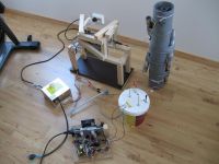
I have no way of measuring the anode voltage unfortunately. I have tested the multiplier and transformer before, and they should be capable of 3kW. I doubt supplying 100W or even 500W is a problem. See the video I made of the multiplier arcing (through a water resistor). I do have 1000x 1M mini-resistors which I bought for this purpose, but not the will power to solder them together. I would greatly appreciate it if you could send the resistors. Soldering 5 beats 1000! How much do you want for them?
I just now did some more testing today. I increased the filament voltage further, up to 1.6V and it glows white now. To see if it's working at all I placed some photographic paper in the intensifier screen, and x-rayed it for 10-20s. The tube doesn't get warm and the paper was unexposed after development. I also tried measuring the anode current again, but the multiplier ruins my readings. Same goes for the ionization chamber, even at some meters range. I did a crude voltage test, with a salt-water resistor placed at the anode. While the set-up was running as normal I drew an arc from the resistor. The arc initiated at 4 cm, suggesting only 40kV. I don't find this surprising as the transformer is actually wound for 10kV, but ringing and other effects seem to give twice the output voltage (at least when the arc first initiates). I'm guessing the multiplier is loading down the transformer enough for it to behave ideally again, which only gives me 40kV. Still, I would expect the anode to become warm and some fluorescence on the screens at the very least.
uzzors2k, Sat Feb 28 2009, 04:09PM
My ionization chamber became desensitized after the very first test. I had it directly under the tube thinking it was shielded from HV ions with all the tin-foil, which it wasn't. The reading is now -30mV with just background radiation and just 12mV with the radium watch-hands VS 30mV background and 300mV watch-hands before. I assume the pA-sensing Darlington has suffered, I'll replace it later. Either way, before the first tests I was unsure of it's practical use since it takes so long for the reading to stabilize. I made a small 130V inverter which boosts the chamber voltage and increases speed and sensitivity, but it still takes several seconds for the reading to stabilize. And if exposures are in the 1-5 second range that's a bit impractical.
The plan was to run about 500µA to 2mA of current through the tube for reasonable x-ray intensity and low tube power. It's easier to manage long exposures than ones in the ms range, especially when anode voltage takes some time to climb. I have no idea how filament temperature and anode current correspond together, so I thought it would be safe to start with the filament barely warm. I've heard tubes can be damaged by low filament temperatures before, but never understood how or why. Could you explain? I have run the tube without the filament heated to check if my machine could withstand the HV, but otherwise I always let the filament warm up first. If it's actually warm enough is another matter.

I have no way of measuring the anode voltage unfortunately. I have tested the multiplier and transformer before, and they should be capable of 3kW. I doubt supplying 100W or even 500W is a problem. See the video I made of the multiplier arcing (through a water resistor).
 I do have 1000x 1M mini-resistors which I bought for this purpose, but not the will power to solder them together. I would greatly appreciate it if you could send the resistors. Soldering 5 beats 1000! How much do you want for them?
I just now did some more testing today. I increased the filament voltage further, up to 1.6V and it glows white now. To see if it's working at all I placed some photographic paper in the intensifier screen, and x-rayed it for 10-20s. The tube doesn't get warm
 and the paper was unexposed after development. I also tried measuring the anode current again, but the multiplier ruins my readings. Same goes for the ionization chamber, even at some meters range. I did a crude voltage test, with a salt-water resistor placed at the anode. While the set-up was running as normal I drew an arc from the resistor. The arc initiated at 4 cm, suggesting only 40kV. I don't find this surprising as the transformer is actually wound for 10kV, but ringing and other effects seem to give twice the output voltage (at least when the arc first initiates). I'm guessing the multiplier is loading down the transformer enough for it to behave ideally again, which only gives me 40kV. Still, I would expect the anode to become warm and some fluorescence on the screens at the very least.
Re: Uzzors' Coolidge X-ray Machine
Proud Mary, Sat Feb 28 2009, 05:33PM
The 5 x 200M 2W resistors are a gift. I have many happy memories of Norway. If you'd like to send me your address in a private message, I'll put the resistors in the post on Monday morning, together with anything else that might be useful.
Why is low heater voltage damaging? It can sometimes over a period of time cause a condition called "cathode stripping." - stripping of the barium oxide cathode coating. But low heater voltage is not at all likely to result in immediate catastrophe, as can excessive heater voltage. The biggest stress on heaters is the surge that flows at the moment of switching on, as the heating element expands, bends and flexes as it expands.
So you should always increase heater voltage only gradually, Erik.
An X-ray tube is no more than a special case of a diode valve, and there are two basic failure mechanisms:
1. Heater failure. You know this has not happened because your heater lights up.
2. Vacuum loss. If your tube is unable to maintain high-voltage stand-off, but starts arcing inside when the anode is at 20 - 30kV then you have lost some vacuum. (Arcing at full voltage (70kV in your case) is not necessarily a sign of failure, but may be the operating conditions are not set properly.)
If there is any sign of barium oxide - a white powdery material - around the heater pins or the anode structure, then your tube is definitely gone. (The BaO is produced by the conversion of all the getter into its oxide)
You need to put a moving coil meter on the cold, Earth side of the tube so you can see what is going on, Erik. I have a box of 50-0-50uA somewhere and will send you one, but you'll have to make your own shunt.
My guess is that your tube is not gone, but that you don't have enough HT, but we shall see!
Don't wreck it before you get the measuring kit from me!

Re: Uzzors' Coolidge X-ray Machine
uzzors2k, Fri Mar 13 2009, 07:41PM
With the marvelous contribution from Harry I now have some more insight into what my x-ray machine is up to. I was given a moving coil ammeter, a bunch of high resistance and precision resistors for the voltage divider, and some extra goodies! I must say the meter looks cool on the x-ray machine! Thanks a bunch, Harry!
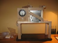
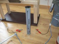
Today I took some measurements.
1) There is no current flowing through the tube, even with the filament heated. If there is any it's below 1~10µA.
2) The output voltage from the CW multiplier is 48 - 50kV. That should be enough for testing, as the D model is rated for 40-70kV. I'll see if I can't add another stage to the CW tower, which should boost it up to 60kV.
Currently I run the filament at 1.5V, at the most. Given a total lack of current flowing through the tube, Harry expecting the filament to require 5V and various x-ray datasheets quoting filament voltages in the same region I'm going to buff up the filament driver. I should be ready to test with increased filament current tomorrow.
uzzors2k, Fri Mar 13 2009, 07:41PM
With the marvelous contribution from Harry I now have some more insight into what my x-ray machine is up to. I was given a moving coil ammeter, a bunch of high resistance and precision resistors for the voltage divider, and some extra goodies! I must say the meter looks cool on the x-ray machine! Thanks a bunch, Harry!


Today I took some measurements.
1) There is no current flowing through the tube, even with the filament heated. If there is any it's below 1~10µA.
2) The output voltage from the CW multiplier is 48 - 50kV. That should be enough for testing, as the D model is rated for 40-70kV. I'll see if I can't add another stage to the CW tower, which should boost it up to 60kV.
Currently I run the filament at 1.5V, at the most. Given a total lack of current flowing through the tube, Harry expecting the filament to require 5V and various x-ray datasheets quoting filament voltages in the same region I'm going to buff up the filament driver. I should be ready to test with increased filament current tomorrow.
Re: Uzzors' Coolidge X-ray Machine
Proud Mary, Fri Mar 13 2009, 10:41PM
Eirik, I would expect some tens of uA at least of anode current by this stage - even if it is only cold cathode field emission - but think you must increase the heater voltage to 5V to be sure. Remember that in this tyoe of tube, X-ray intensity is usually controlled by varying the heater voltage/temperature, while the anode voltage (much harder to regulate) remains constant.
If that tube is dead, I will send you a PD500 shunt stabiliser triode which will most certainly produce a strong output at 50kV, though not as well focused as the Coolidge would have been.
So don't despair! If the Coolidge tube is kaputt, you'll soon have something else to make all your hard work worthwhile!

Re: Uzzors' Coolidge X-ray Machine
uzzors2k, Sat Mar 14 2009, 05:30PM
IT WORKS!
I had to increase the filament voltage to about 3V, (that regulator you gave me came in handy, Harry ) once in that range the tube rapidly starts conducting, and small changes in filament voltage cause large swings in anode current. Currently I've taken 4 x-rays. The anode current is about 3mA and the voltage a meager 40~45kV.
I was about to give up after the first x-ray, as nothing was showing up while the paper was under the developer. Little did I know it took much longer than when simply exposing the paper to bright light! Development times with rapid fixer are some 2 - 10 minutes, though the contrast is good after 5 min. I expose the cassette and objects at 15cm range, for 30 to 50 seconds. Greater distances would improve sharpness, but greatly increase exposure time. Here are the last two x-rays.

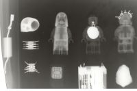
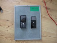
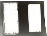
As evident in the ipod and cell phone exposure the anode voltage isn't high enough for penetrating radiation. Just look at the spikes on the Tesla-Lego figure's helmet, which consist of nothing but 1/2W resistor lead wire. I'm going to upgrade my CW tower now, and hope the voltage doesn't sag.
uzzors2k, Sat Mar 14 2009, 05:30PM
IT WORKS!

I had to increase the filament voltage to about 3V, (that regulator you gave me came in handy, Harry
 ) once in that range the tube rapidly starts conducting, and small changes in filament voltage cause large swings in anode current. Currently I've taken 4 x-rays. The anode current is about 3mA and the voltage a meager 40~45kV.
I was about to give up after the first x-ray, as nothing was showing up while the paper was under the developer. Little did I know it took much longer than when simply exposing the paper to bright light! Development times with rapid fixer are some 2 - 10 minutes, though the contrast is good after 5 min. I expose the cassette and objects at 15cm range, for 30 to 50 seconds. Greater distances would improve sharpness, but greatly increase exposure time. Here are the last two x-rays.


As evident in the ipod and cell phone exposure the anode voltage isn't high enough for penetrating radiation. Just look at the spikes on the Tesla-Lego figure's helmet, which consist of nothing but 1/2W resistor lead wire. I'm going to upgrade my CW tower now, and hope the voltage doesn't sag.
Re: Uzzors' Coolidge X-ray Machine
Proud Mary, Sat Mar 14 2009, 06:30PM
That's marvellous, Eirik! Well done! I knew you could do it!
Increasing KVA will certainly increase sharpness, as the low energy X-rays always produce more "woolly" images. But as you say, the more Cockcroft stages the greater the 'sag', and you may start to lose current too. You'll just have to try it and see.
Perhaps now is the time to start thinking about a reliable ionization chamber, so you will have a better idea of what is going on with the rays as they travel in and around your room!
Now you have some data, you can enter it in RadPro and see how many Sv/hr you have. You may be surprised!
Proud Mary, Sat Mar 14 2009, 06:30PM
That's marvellous, Eirik! Well done! I knew you could do it!
Increasing KVA will certainly increase sharpness, as the low energy X-rays always produce more "woolly" images. But as you say, the more Cockcroft stages the greater the 'sag', and you may start to lose current too. You'll just have to try it and see.
Perhaps now is the time to start thinking about a reliable ionization chamber, so you will have a better idea of what is going on with the rays as they travel in and around your room!

Now you have some data, you can enter it in RadPro and see how many Sv/hr you have. You may be surprised!

Re: Uzzors' Coolidge X-ray Machine
Download, Sun Mar 15 2009, 09:05AM
I've just got to get my flyback driver working and I'll start making xray pics
Download, Sun Mar 15 2009, 09:05AM
Uzzors wrote ...
IT WORKS!
I had to increase the filament voltage to about 3V, (that regulator you gave me came in handy, Harry ) once in that range the tube rapidly starts conducting, and small changes in filament voltage cause large swings in anode current. Currently I've taken 4 x-rays. The anode current is about 3mA and the voltage a meager 40~45kV.
I was about to give up after the first x-ray, as nothing was showing up while the paper was under the developer. Little did I know it took much longer than when simply exposing the paper to bright light! Development times with rapid fixer are some 2 - 10 minutes, though the contrast is good after 5 min. I expose the cassette and objects at 15cm range, for 30 to 50 seconds. Greater distances would improve sharpness, but greatly increase exposure time. Here are the last two x-rays.


As evident in the ipod and cell phone exposure the anode voltage isn't high enough for penetrating radiation. Just look at the spikes on the Tesla-Lego figure's helmet, which consist of nothing but 1/2W resistor lead wire. I'm going to upgrade my CW tower now, and hope the voltage doesn't sag.
Very nice!IT WORKS!

I had to increase the filament voltage to about 3V, (that regulator you gave me came in handy, Harry
 ) once in that range the tube rapidly starts conducting, and small changes in filament voltage cause large swings in anode current. Currently I've taken 4 x-rays. The anode current is about 3mA and the voltage a meager 40~45kV.
I was about to give up after the first x-ray, as nothing was showing up while the paper was under the developer. Little did I know it took much longer than when simply exposing the paper to bright light! Development times with rapid fixer are some 2 - 10 minutes, though the contrast is good after 5 min. I expose the cassette and objects at 15cm range, for 30 to 50 seconds. Greater distances would improve sharpness, but greatly increase exposure time. Here are the last two x-rays.


As evident in the ipod and cell phone exposure the anode voltage isn't high enough for penetrating radiation. Just look at the spikes on the Tesla-Lego figure's helmet, which consist of nothing but 1/2W resistor lead wire. I'm going to upgrade my CW tower now, and hope the voltage doesn't sag.
I've just got to get my flyback driver working and I'll start making xray pics
Re: Uzzors' Coolidge X-ray Machine
uzzors2k, Sun Mar 15 2009, 09:58PM
Thanks. I've ordered parts for the CW upgrade, hopefully it will be ready for next weekend.
uzzors2k, Sun Mar 15 2009, 09:58PM
Thanks. I've ordered parts for the CW upgrade, hopefully it will be ready for next weekend.
Re: Uzzors' Coolidge X-ray Machine
uzzors2k, Wed Mar 25 2009, 10:25PM
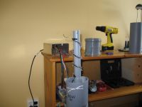
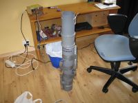
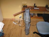
Alrighty, my totem of manhood has been jacked up two notches. The output voltage is around 70kV no load, I haven't measured throughly nor under load yet. It should hold up enough to give much more penetrating x-rays this time. I expect to try it out this weekend.
uzzors2k, Wed Mar 25 2009, 10:25PM
Alrighty, my totem of manhood has been jacked up two notches. The output voltage is around 70kV no load, I haven't measured throughly nor under load yet. It should hold up enough to give much more penetrating x-rays this time. I expect to try it out this weekend.


Re: Uzzors' Coolidge X-ray Machine
Proud Mary, Thu Mar 26 2009, 02:10AM
Great stuff, Eirik!
Remember that the 1G potential divider will draw off 70uA - 3.4W - at 70kV, so I would expect the tube voltage to jump up quite a bit when you disconnect the divider, unless you are sure you have power enough to spare to prevent 'sag'.
I've just remembered that I've got some Cold War era quartz fibre dosimeters in a box somewhere - you charge them to 300V, set the zero, and get a direct reading in mR when you look through it against the light like a little microscope. They're the size of a fat fountain pen with an aluminium body. I don't suppose they're wonderfully accurate, but located at centre beam at 5 - 10cm you will get a high enough reading to expect a fair degree of accuracy.
I'll put one in the post to you in the next few days, because it's really essential that you have some idea of what is coming out of your tube. It would be negligent not to know, lad.
It measures accumulated dose, so if you charge it and leave it on your workbench you can measure the dose received at that position up to a period of several days (before leakage means that the instrument has to be recharged)
I hope to unveil THOR, my single-shot solid-dielectric-gap pulse power flash machine in the projects section in the near future. I am having difficulty making a suitable cart for it, and am looking out for a discarded supermarket trolley (kart) to saw the wheel assemblies and weld them onto a new chassis. Trolleys pulled out of the river will do fine so long as they haven't been in the water for too long. (A terrible testament of our times! )
)
In the meantime, if there are any small bits and pieces you need to get on with your own machine don't be afraid to ask, as I may well have them knocking about somewhere.
Keep up the good work, Eirik!

Thor's Battle Against the Giants
MÃ¥rten Eskil Winge, 1872
Proud Mary, Thu Mar 26 2009, 02:10AM
Great stuff, Eirik!
Remember that the 1G potential divider will draw off 70uA - 3.4W - at 70kV, so I would expect the tube voltage to jump up quite a bit when you disconnect the divider, unless you are sure you have power enough to spare to prevent 'sag'.
I've just remembered that I've got some Cold War era quartz fibre dosimeters in a box somewhere - you charge them to 300V, set the zero, and get a direct reading in mR when you look through it against the light like a little microscope. They're the size of a fat fountain pen with an aluminium body. I don't suppose they're wonderfully accurate, but located at centre beam at 5 - 10cm you will get a high enough reading to expect a fair degree of accuracy.
I'll put one in the post to you in the next few days, because it's really essential that you have some idea of what is coming out of your tube. It would be negligent not to know, lad.
It measures accumulated dose, so if you charge it and leave it on your workbench you can measure the dose received at that position up to a period of several days (before leakage means that the instrument has to be recharged)
I hope to unveil THOR, my single-shot solid-dielectric-gap pulse power flash machine in the projects section in the near future. I am having difficulty making a suitable cart for it, and am looking out for a discarded supermarket trolley (kart) to saw the wheel assemblies and weld them onto a new chassis. Trolleys pulled out of the river will do fine so long as they haven't been in the water for too long. (A terrible testament of our times!
 )
)In the meantime, if there are any small bits and pieces you need to get on with your own machine don't be afraid to ask, as I may well have them knocking about somewhere.
Keep up the good work, Eirik!


Thor's Battle Against the Giants
MÃ¥rten Eskil Winge, 1872
Re: Uzzors' Coolidge X-ray Machine
uzzors2k, Thu Mar 26 2009, 04:32PM
That sounds great, Harry. I'll wait until the dosimeter comes before testing again then. I used RadPro to find my current exposure. With the intensity I'm exposed to being only 6.663993E-013 µSv/hr, and my total exposure time 2,5 minutes, I consider it quite negligible. 2.8*10^-17 mSv. Increasing the tube voltage from 50 to 70kV greatly increases the exposure though! An order of 10^11!
Your project sounds intriguing, Harry. Single-shot x-ray exposure, yikes!
Re: Uzzors' Coolidge X-ray Machine
Proud Mary, Fri Mar 27 2009, 01:09PM
Hei Eirik! I will do my best to post your dosimetry kit by the end of today, but if I can't find the time, it won't go off until Monday.
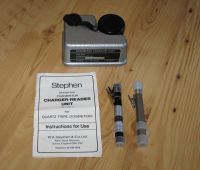
I am able to spare a 200cGy and a 500cgy quartz fibre dosimeter, a Stephen charger unit, and its instruction manual.
As RBE (Q) for electron and photon radiation is 1, the instruments can be directly read out as 0-2 Sv and 0-5 Sv respectively.
The 500cGy unit is a brand new Dosimeter Corporation Gamma & X-Ray Dosimeter Model 673 calibrated in 20cGy steps.
The 200cGy unit is in good used condition and is calibrated in 10cGy steps.
You will need a 1.5V alkaline D cell to power the charger unit, which weighs quite enough without the expense of sending a battery for it.
Both units will detect beta particles >1MeV.
Measurement compensation. I suggest you use the instruments together with an aluminium filter over the tube, since radiation below the aluminium K edge will not be able to penetrate the dosimeters.
If using the dosimeters close to the tube, I suggest you place them in a thin-walled aluminium tube such as cigar tube with a good low resistance earth connection to shield the instruments from strong local coulomb forces which could disturb the tiny charge on the quartz fibre.
I most strongly suggest that you investigate your calibration standads as follows. Taking take to set up true 90 deg rightangles (!) position the 200cGy instrument in its Faraday shield at a distance d from the anode at centre beam. I would suggest 150mm or 200mm for your first attempt. Making a few trials runs, (and recharging and resetting the dosimeter between each) determine very approximately the time t required to bring the dosimeter up to 66% of full scale - roughly around 130cGy - where a 200cGy instrument can be expected to be most accurate. Apply filament current and wait for five minutes to allow the filament to reach its stable working termperature and reach thermal equilibrium with the tube structure. Now start your stop watch, and apply anode voltage. After the time t previously estimated for a dose of 130cGy switch off your HT voltage, and stop your clock. Remove your dosimeter in its earthed Faraday tube to a good distance from the apparatus, and quickly bleed off any remaining HT in your C&W with the potential divider voltmeter. Use an Earth Probe to shunt off any remaining charges in and around the apparatus and any large local metal parts which might have accumulated charges on them.
Now open your dosimeter Faraday shield and take your reading.
You now have the parameters time, distance, dose, anode voltage, and aluminium filter thickness to enter into RadPro, and can directly compare the actual reading with the predictions of RadPro.
Repeat the exact procedure and conditions as many times as your interest in it can be made to last!
Now increase the distance in increments, repeating the same procedure for each, and comparing each empirical reading with the RadPro prediction.
When you can stand not one more minute of this dull routine, you must
Remember at all costs that at this stage you are in maximum danger, and your personal survival may depend on a serious investment in Lyst Sterkøl to cope with repeating the entire set of procedures all over again with the 500cGy instrument the following day.
Work up your data forwards and backwards, draw your graphs, and you will have your first calibration curves, and confidence regions.
There is no need to do anything quite so boring for a very long time, or until you acquire a third instrument, which you can compare with the two first.
So you've got your dosimetry kit, a good brain, and the RadPro calculator, and rest is up to you... why not try some real experiments beyond the usual radiographs of mobile phones and sea shells?
One you may enjoy is the X-ray pin-hole camera, with which you will be able to image the anode, and thereby see the exact source of the radiation, a powerful experimental tool. Once you have imaged the anode, you might try bringing in a strong neodymium magnet to observe the active spot's deflection. You might also try to find out how the active spot may be altered by a strong alternating magnetic field.
You could attempt the early, simpler forms of X-ray crystallography....
But I've no business telling you how you should do your science!
My chief reward is knowing that you now have some basic safety equipment, but I would very much enjoy a piece of ordinary supermarket geitost if this is not too much to ask.
If there is space in the dosimeter parcel box, which I have not yet put together, I will include a few small EHT valves known to be good cold cathode X-ray emitters, as they weigh almost nothing compared with the Stephens charger unit. Run them under oil at 35 - 45kV or they will flash over, or fail due to glass dielectric puncture. But they will work for a few hours each, and cost only a few kronor, so it is no great loss when they fail. Don't heat the filament, so they are forced to conduct in cold cathode field emission mode. Don't let Ia exceed 40-50uA, or they will fail in minutes.
It would make a first class project to use the pin-hole camera to image the X-ray emission from a collection of old EHT diodes, since there will be no focal spot, as with your main dental tube, but numerous sources of emission of different intensities from different points within the valve structure.
I will write of THOR in a private message when I have the time. I must get on with my day now.
Vi snakkes!:-)
Harry.
Proud Mary, Fri Mar 27 2009, 01:09PM
Hei Eirik! I will do my best to post your dosimetry kit by the end of today, but if I can't find the time, it won't go off until Monday.
I am able to spare a 200cGy and a 500cgy quartz fibre dosimeter, a Stephen charger unit, and its instruction manual.
As RBE (Q) for electron and photon radiation is 1, the instruments can be directly read out as 0-2 Sv and 0-5 Sv respectively.
The 500cGy unit is a brand new Dosimeter Corporation Gamma & X-Ray Dosimeter Model 673 calibrated in 20cGy steps.
The 200cGy unit is in good used condition and is calibrated in 10cGy steps.
You will need a 1.5V alkaline D cell to power the charger unit, which weighs quite enough without the expense of sending a battery for it.
Both units will detect beta particles >1MeV.
Measurement compensation. I suggest you use the instruments together with an aluminium filter over the tube, since radiation below the aluminium K edge will not be able to penetrate the dosimeters.
If using the dosimeters close to the tube, I suggest you place them in a thin-walled aluminium tube such as cigar tube with a good low resistance earth connection to shield the instruments from strong local coulomb forces which could disturb the tiny charge on the quartz fibre.
I most strongly suggest that you investigate your calibration standads as follows. Taking take to set up true 90 deg rightangles (!) position the 200cGy instrument in its Faraday shield at a distance d from the anode at centre beam. I would suggest 150mm or 200mm for your first attempt. Making a few trials runs, (and recharging and resetting the dosimeter between each) determine very approximately the time t required to bring the dosimeter up to 66% of full scale - roughly around 130cGy - where a 200cGy instrument can be expected to be most accurate. Apply filament current and wait for five minutes to allow the filament to reach its stable working termperature and reach thermal equilibrium with the tube structure. Now start your stop watch, and apply anode voltage. After the time t previously estimated for a dose of 130cGy switch off your HT voltage, and stop your clock. Remove your dosimeter in its earthed Faraday tube to a good distance from the apparatus, and quickly bleed off any remaining HT in your C&W with the potential divider voltmeter. Use an Earth Probe to shunt off any remaining charges in and around the apparatus and any large local metal parts which might have accumulated charges on them.
Now open your dosimeter Faraday shield and take your reading.
You now have the parameters time, distance, dose, anode voltage, and aluminium filter thickness to enter into RadPro, and can directly compare the actual reading with the predictions of RadPro.
Repeat the exact procedure and conditions as many times as your interest in it can be made to last!
Now increase the distance in increments, repeating the same procedure for each, and comparing each empirical reading with the RadPro prediction.
When you can stand not one more minute of this dull routine, you must
Remember at all costs that at this stage you are in maximum danger, and your personal survival may depend on a serious investment in Lyst Sterkøl to cope with repeating the entire set of procedures all over again with the 500cGy instrument the following day.
Work up your data forwards and backwards, draw your graphs, and you will have your first calibration curves, and confidence regions.
There is no need to do anything quite so boring for a very long time, or until you acquire a third instrument, which you can compare with the two first.
So you've got your dosimetry kit, a good brain, and the RadPro calculator, and rest is up to you... why not try some real experiments beyond the usual radiographs of mobile phones and sea shells?
One you may enjoy is the X-ray pin-hole camera, with which you will be able to image the anode, and thereby see the exact source of the radiation, a powerful experimental tool. Once you have imaged the anode, you might try bringing in a strong neodymium magnet to observe the active spot's deflection. You might also try to find out how the active spot may be altered by a strong alternating magnetic field.
You could attempt the early, simpler forms of X-ray crystallography....
But I've no business telling you how you should do your science!

My chief reward is knowing that you now have some basic safety equipment, but I would very much enjoy a piece of ordinary supermarket geitost if this is not too much to ask.
If there is space in the dosimeter parcel box, which I have not yet put together, I will include a few small EHT valves known to be good cold cathode X-ray emitters, as they weigh almost nothing compared with the Stephens charger unit. Run them under oil at 35 - 45kV or they will flash over, or fail due to glass dielectric puncture. But they will work for a few hours each, and cost only a few kronor, so it is no great loss when they fail. Don't heat the filament, so they are forced to conduct in cold cathode field emission mode. Don't let Ia exceed 40-50uA, or they will fail in minutes.
It would make a first class project to use the pin-hole camera to image the X-ray emission from a collection of old EHT diodes, since there will be no focal spot, as with your main dental tube, but numerous sources of emission of different intensities from different points within the valve structure.
I will write of THOR in a private message when I have the time. I must get on with my day now.
Vi snakkes!:-)
Harry.
Re: Uzzors' Coolidge X-ray Machine
c4r0, Sun Mar 29 2009, 01:07PM
Hello! Great work! Are you going to put this on your website?
c4r0, Sun Mar 29 2009, 01:07PM
Hello! Great work!
 Are you going to put this on your website?
Re: Uzzors' Coolidge X-ray Machine
uzzors2k, Sun Mar 29 2009, 02:05PM
Hey Karol, I plan to put it on my site during the Easter holidays. I just want to try it with a higher anode voltage first, so the x-rays are more impressive.
uzzors2k, Sun Mar 29 2009, 02:05PM
Hey Karol, I plan to put it on my site during the Easter holidays. I just want to try it with a higher anode voltage first, so the x-rays are more impressive.
Re: Uzzors' Coolidge X-ray Machine
Proud Mary, Thu Apr 23 2009, 06:39PM
Hei Eirik, here are the size comparative pictures of X-ray sensitive GM tube G26 compared with assorted 'ordinary' beta-gamma GM tubes, that we've been talking about:
They are from top to bottom:
1. ZP1313 (small insensitive type for gamma dosimetry) 500V threshold
2. ZP1401 (small gamma) 400V threshold
3. ZP1481 (MX168) beta, gamma, 400V thresh.
4. B12H (sensitive beta gamma) 370V thresh.
5. G26 - X-ray GM tube 1160V. thresh.
Scale: the G-26 is 37cm long including the pins on the ceramic base. It is filled with Ar at about 60% atmospheric pressure - very high compared with the beta-gamma tubes.
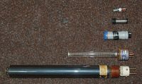
An important difference of use: X-ray GM tubes are most sensitive axially - when pointed directly at the source - so that the photons will undergo the maximum number of collisions with the gas in the tube -which is why it is so much longer. All the glass types must be operated in total darkness, including G-26.
Proud Mary, Thu Apr 23 2009, 06:39PM
Hei Eirik, here are the size comparative pictures of X-ray sensitive GM tube G26 compared with assorted 'ordinary' beta-gamma GM tubes, that we've been talking about:
They are from top to bottom:
1. ZP1313 (small insensitive type for gamma dosimetry) 500V threshold
2. ZP1401 (small gamma) 400V threshold
3. ZP1481 (MX168) beta, gamma, 400V thresh.
4. B12H (sensitive beta gamma) 370V thresh.
5. G26 - X-ray GM tube 1160V. thresh.
Scale: the G-26 is 37cm long including the pins on the ceramic base. It is filled with Ar at about 60% atmospheric pressure - very high compared with the beta-gamma tubes.

An important difference of use: X-ray GM tubes are most sensitive axially - when pointed directly at the source - so that the photons will undergo the maximum number of collisions with the gas in the tube -which is why it is so much longer. All the glass types must be operated in total darkness, including G-26.
Re: Uzzors' Coolidge X-ray Machine
uzzors2k, Fri Apr 24 2009, 04:37PM
Interesting. The difference in size really demonstrates the inadequacy of standard Geiger tubes for detecting x-rays. The tube in my GM counter is about the size of your ZP1313 tube...
Project update:
My good friend Harry has donated even more! Among the goodies he sent is a quartz fibre dosimeter set. With the dosimeter tubes I'll be able to accurately measure the cumulative dose from the x-ray tube over a longer course of time. I'll find time within the next few weeks to test them out AND take some images with more penetrating x-rays. After that I promise to make a write up for my website.


Re: Uzzors' Coolidge X-ray Machine
Proud Mary, Fri Apr 24 2009, 05:36PM
There are other factors, such as window and wall thickness, use of special metals etc, but Sensitivity is roughly related to volume. The more gas, the more collisions.
Proud Mary, Fri Apr 24 2009, 05:36PM
Uzzors wrote ...
Interesting. The difference in size really demonstrates the inadequacy of standard Geiger tubes for detecting x-rays. The tube in my GM counter is about the size of your ZP1313 tube...
Interesting. The difference in size really demonstrates the inadequacy of standard Geiger tubes for detecting x-rays. The tube in my GM counter is about the size of your ZP1313 tube...
There are other factors, such as window and wall thickness, use of special metals etc, but Sensitivity is roughly related to volume. The more gas, the more collisions.
Re: Uzzors' Coolidge X-ray Machine
Proud Mary, Fri May 01 2009, 02:56AM
Hei Eirik,
I've just got two sets of these X-ray proportional counters, and will lend you one when you move on to the next stage.
Each set covers the range 2 - 50keV, as follows:
SI11R-1 Ar + 10% CH4 1650V max
SI11R-2 Kr + 10% CH4 1700V max
SI11R-3 He + 10% CH4 1980V max
SI11R-4 Ne + 10% CH4 1250V max
The max. figures are the highest at which the tubes can be operated before they enter the Geiger region.
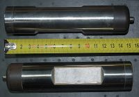
You can see there are beryllium windows on both sides, so the rays go in one side and come out of the other. Flink?
The krypton tube covers the range 10keV to 50keV and is perhaps the most useful.
These tubes, together with a collection of filters, make it possible to determine exactly what soft X-rays are being produced, always a nightmare with experimental devices. To use them in proportional mode requires low noise linear amplifiers.
Proud Mary, Fri May 01 2009, 02:56AM
Hei Eirik,
I've just got two sets of these X-ray proportional counters, and will lend you one when you move on to the next stage.
Each set covers the range 2 - 50keV, as follows:
SI11R-1 Ar + 10% CH4 1650V max
SI11R-2 Kr + 10% CH4 1700V max
SI11R-3 He + 10% CH4 1980V max
SI11R-4 Ne + 10% CH4 1250V max
The max. figures are the highest at which the tubes can be operated before they enter the Geiger region.
You can see there are beryllium windows on both sides, so the rays go in one side and come out of the other. Flink?

The krypton tube covers the range 10keV to 50keV and is perhaps the most useful.
These tubes, together with a collection of filters, make it possible to determine exactly what soft X-rays are being produced, always a nightmare with experimental devices. To use them in proportional mode requires low noise linear amplifiers.
Re: Uzzors' Coolidge X-ray Machine
uzzors2k, Sat May 09 2009, 07:07PM
I did some more experiments with my x-ray machine this weekend. The main change from last time is increased anode voltage. It was measured to be 65-75kV during exposures. This improved the penetration of the rays somewhat, giving reasonable x-rays of my Ipod and cell phone. Here's the new radiographs:
Softgun for shooting plastic BBs.
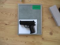
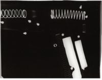
TV flyback multiplier, digital watch and dosimeter.
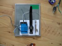
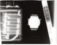
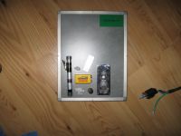
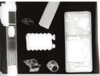
Dosimeter, sea shells, Ipod, NiCad Battery and 0.5mm steel transformer lamination.
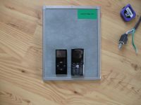
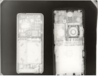
Ipod nano and k750i.
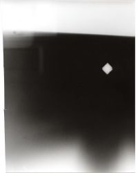
I had a hard time finding a metal plate suitable for a pinhole camera, but I figured a close-up exposure of the anode would reveal the size of the focal spot nicely. A small neodymium magnet was placed approximately under the center of the anode for reference. Due to the shield and cassette size I couldn't get close enough for a real good image, but it's close enough to give an outline of the main beam area. Above the magnet one can see the sharp shadow from the "anode heel effect". The tilt is probably due to the anode and cassette not being precisely parallel. As is visible from the exposure, the intensity diminishes rapidly behind the anode and to some extent behind the cathode. Out to the sides the intensity gradually decreases, but doesn't really become negligible until directly above the anode. I didn't use a filter for the image, and judging by checks with my dosimeter most of the higher energy x-rays are radiated in a wider angle than the image would suggest.
Sorry Harry, but I couldn't take a large amount of exposures to calibrate the dosimeters. I took 6 controlled exposures where the exact position of the dosimeters was noted, exposure time, anode voltage and current. With convincing everyone in the house to move to a safe location and the cool-down time of the anode I can only fit so many exposures in a day. Unfortunately there were more variables than predicted, more on that later. Two of the exposures were to determine the beam size and intensity at various locations. Above the anode, behind the cathode, and various angles to the main beam. The other four were to determine the intensity in the main beam, and in these both dosimeters were used simultaneously, placed symmetrically and at the same distance. The error between them was small, and consistent (the 500cGy would count less by a factor of ca 5% compared to the 200cGy dosimeter). Leading me to believe they are well enough calibrated for my use.
I suspected a problem when RadPro gave intensities that were between 2 and 4 times what I had measured. Checking my notes I saw the power drawn by the entire setup was much too low when considering the voltage and current the tube was supposedly operated at. So I measured the power draw of my CW with no load, which is nearly exactly 115W. The power during a normal x-ray session is 255W, leaving less than 140W for the tube. After some investigating I found I had forgotten to ground the meter! The casing was collecting a charge which in turn would deflect the needle in the direction is was already pointed at! So all of my previous current measurements are wrong.... The estimated current used in my radiographs is between 1 and 2mA, hence the relatively long exposure times of 30s+.
Despite this, I've determined the output of my tube to be 68 Gy/hr at 10cm from the anode spot, at 70kV and ~1.5mA. Using the Inverse Square Law this number matches well to the exposures the dosimeters collected at different distances, so at least it's constant. The dosimeters have an aluminium case which filters a large portion of low energy x-rays, so the dose would be even greater to living tissue!
This number is much too low according RadPro however. I still don't trust the x-ray calculator in RadPro. I've encountered several things which don't seem to model the type of X-ray source I'm dealing with. For one thing, the filter and shield calculator. They should give the exact same result when using similar materials, but don't. Try it yourself. Have I misunderstood the difference between a filter and a shield? Also the exact anode voltage can swing the exposure rate by a factor of 100. Try 55kV against 56kV for example. In a real-world device such as mine the two x-ray spectra should be nearly identical, so the dose would be practically the same. I suspect it's modeling a beam of X-rays with only one specific energy, not a spectrum, which would explain the rapid drops in intensity based on voltage.
Well, that concludes the x-ray adventures of Uzzors for now! I've seen what I wanted to, and quite frankly I'm becoming worried about x-ray scatter. My machine only has directional shielding, leaving me pretty exposed to any scattered rays. My future plans are to shield the entire tube, get an aluminium filter for the output beam and arrange a cooling system for the anode. Possibly also modify the machine for taking digital X-rays, which would reduce exposure times greatly I imagine. Don't expect any of this to be done any time soon however, other projects are begging to be done! I'll try to post this on my site within the next few weeks.
uzzors2k, Sat May 09 2009, 07:07PM
I did some more experiments with my x-ray machine this weekend. The main change from last time is increased anode voltage. It was measured to be 65-75kV during exposures. This improved the penetration of the rays somewhat, giving reasonable x-rays of my Ipod and cell phone. Here's the new radiographs:
Softgun for shooting plastic BBs.


TV flyback multiplier, digital watch and dosimeter.


Dosimeter, sea shells, Ipod, NiCad Battery and 0.5mm steel transformer lamination.


Ipod nano and k750i.


I had a hard time finding a metal plate suitable for a pinhole camera, but I figured a close-up exposure of the anode would reveal the size of the focal spot nicely. A small neodymium magnet was placed approximately under the center of the anode for reference. Due to the shield and cassette size I couldn't get close enough for a real good image, but it's close enough to give an outline of the main beam area. Above the magnet one can see the sharp shadow from the "anode heel effect". The tilt is probably due to the anode and cassette not being precisely parallel. As is visible from the exposure, the intensity diminishes rapidly behind the anode and to some extent behind the cathode. Out to the sides the intensity gradually decreases, but doesn't really become negligible until directly above the anode. I didn't use a filter for the image, and judging by checks with my dosimeter most of the higher energy x-rays are radiated in a wider angle than the image would suggest.

Sorry Harry, but I couldn't take a large amount of exposures to calibrate the dosimeters. I took 6 controlled exposures where the exact position of the dosimeters was noted, exposure time, anode voltage and current. With convincing everyone in the house to move to a safe location and the cool-down time of the anode I can only fit so many exposures in a day. Unfortunately there were more variables than predicted, more on that later. Two of the exposures were to determine the beam size and intensity at various locations. Above the anode, behind the cathode, and various angles to the main beam. The other four were to determine the intensity in the main beam, and in these both dosimeters were used simultaneously, placed symmetrically and at the same distance. The error between them was small, and consistent (the 500cGy would count less by a factor of ca 5% compared to the 200cGy dosimeter). Leading me to believe they are well enough calibrated for my use.
I suspected a problem when RadPro gave intensities that were between 2 and 4 times what I had measured. Checking my notes I saw the power drawn by the entire setup was much too low when considering the voltage and current the tube was supposedly operated at. So I measured the power draw of my CW with no load, which is nearly exactly 115W. The power during a normal x-ray session is 255W, leaving less than 140W for the tube. After some investigating I found I had forgotten to ground the meter!
 The casing was collecting a charge which in turn would deflect the needle in the direction is was already pointed at! So all of my previous current measurements are wrong.... The estimated current used in my radiographs is between 1 and 2mA, hence the relatively long exposure times of 30s+.
Despite this, I've determined the output of my tube to be 68 Gy/hr at 10cm from the anode spot, at 70kV and ~1.5mA. Using the Inverse Square Law this number matches well to the exposures the dosimeters collected at different distances, so at least it's constant. The dosimeters have an aluminium case which filters a large portion of low energy x-rays, so the dose would be even greater to living tissue!
This number is much too low according RadPro however. I still don't trust the x-ray calculator in RadPro. I've encountered several things which don't seem to model the type of X-ray source I'm dealing with. For one thing, the filter and shield calculator. They should give the exact same result when using similar materials, but don't. Try it yourself. Have I misunderstood the difference between a filter and a shield? Also the exact anode voltage can swing the exposure rate by a factor of 100. Try 55kV against 56kV for example. In a real-world device such as mine the two x-ray spectra should be nearly identical, so the dose would be practically the same. I suspect it's modeling a beam of X-rays with only one specific energy, not a spectrum, which would explain the rapid drops in intensity based on voltage.
Well, that concludes the x-ray adventures of Uzzors for now! I've seen what I wanted to, and quite frankly I'm becoming worried about x-ray scatter. My machine only has directional shielding, leaving me pretty exposed to any scattered rays. My future plans are to shield the entire tube, get an aluminium filter for the output beam and arrange a cooling system for the anode. Possibly also modify the machine for taking digital X-rays, which would reduce exposure times greatly I imagine. Don't expect any of this to be done any time soon however, other projects are begging to be done! I'll try to post this on my site within the next few weeks.
Re: Uzzors' Coolidge X-ray Machine
Proud Mary, Sun May 10 2009, 02:07PM
I thought it was very interesting to see how transparent the actual chamber of your QFD was when compared with the rest of the barrel, so I guess it is machined very thin there.
Now I have some Ne-CH4 proportional tubes, I shall be able to make measurements down to about 4keV. (I couldn't get an He-CH4 tube to cover the range 1 - 4 keV at any price I could afford)
I never expected you would do hundreds of measurements, Eirik! But at least you know what should be done if the need for super-accuracy should arise, or you find yourself having serious doubt about safety - especially, as you suggest, hazardous reflections.
Remember that at your 65kV anode current only about 0.5% of your projectile electron kinetic energy is converted into X-rays, which means your actual X-ray output will be about 0.7.
May I suggest that you try to keep your lowest voltage slightly above 69.5kVa, so you can benefit from the juicy tungsten chanracteristic emission, which will allow you to have a very nice peak at 57.4keV f.eks. With tungsten, K shell electrons have a binding energy of 69.5 keV, and L shell ones 12.1 keV. Thus, your tube's characteristic emission will have an energy of:
69.5 - 12.1 = 57.4 keV
which will stick up out of your Bremmstrahlung output curve like a pointing finger.
Roofing lead, and lead flashing rolls for roof joints and gutters are easy to get (in England, at least) easy to work with with plumber's tools, and you could make a wooden lead-lined box without much difficulty. You can have extra layers of layers in areas of especial vulnerability. The box can be fitted with an air blower and a simple rotary electro-mechanical timer which is less likely to break down than a digital type if unwanted charges should gather on it.
snakkes,
Harry
Proud Mary, Sun May 10 2009, 02:07PM
I thought it was very interesting to see how transparent the actual chamber of your QFD was when compared with the rest of the barrel, so I guess it is machined very thin there.
Now I have some Ne-CH4 proportional tubes, I shall be able to make measurements down to about 4keV. (I couldn't get an He-CH4 tube to cover the range 1 - 4 keV at any price I could afford)
I never expected you would do hundreds of measurements, Eirik!
 But at least you know what should be done if the need for super-accuracy should arise, or you find yourself having serious doubt about safety - especially, as you suggest, hazardous reflections.
Remember that at your 65kV anode current only about 0.5% of your projectile electron kinetic energy is converted into X-rays, which means your actual X-ray output will be about 0.7.
May I suggest that you try to keep your lowest voltage slightly above 69.5kVa, so you can benefit from the juicy tungsten chanracteristic emission, which will allow you to have a very nice peak at 57.4keV f.eks. With tungsten, K shell electrons have a binding energy of 69.5 keV, and L shell ones 12.1 keV. Thus, your tube's characteristic emission will have an energy of:
69.5 - 12.1 = 57.4 keV
which will stick up out of your Bremmstrahlung output curve like a pointing finger.
Roofing lead, and lead flashing rolls for roof joints and gutters are easy to get (in England, at least) easy to work with with plumber's tools, and you could make a wooden lead-lined box without much difficulty. You can have extra layers of layers in areas of especial vulnerability. The box can be fitted with an air blower and a simple rotary electro-mechanical timer which is less likely to break down than a digital type if unwanted charges should gather on it.
snakkes,
Harry

Re: Uzzors' Coolidge X-ray Machine
Proud Mary, Tue May 12 2009, 12:18AM
More comment on your last, Eirik.
"Have I misunderstood the difference between a filter and a shield?"
Perhaps you have! X ray-filters are usually sheets of pure metals or pure alloys of precise combination. Placed in the beam as a lone sheet, or in combinations of different metals and thicknesses, you can create low pass, high pass, wide band pass, and narrow band pass filters for different purposes.
"Shielding" is more like a muffler with broad-band attenuation, and is not usually constructed to be very frequency selective.
"Also the exact anode voltage can swing the exposure rate by a factor of 100."
Suppose you have a tungsten anode (which you do) then simply increasing kVa from 69kV to 70kV will cause a big surge in output as the 69.5keV K-band electrons fall into the 12.1keV L-band holes, creating a big peak of 57.4keV (69.5 - 12.1 = 57.4).
With 70kV on your anode, you will have all the Bremmsstrahlung radiation following the curve common to all X-ray tubes rom 0 keV to 70keV PLUS the big peak at 57.4keV from the exciting of the tungsten, (plus a range of much lesser peaks, emanating from impurities, other effects, etc)
So this gives you a little idea of how a small increase in kVa can cause a sudden surge in output in certain circumstances - and is indeed the basis of X-ray stectroscopy.
You will see how having anodes of iron, copper, nickel, silver, germanium, etc can exploit the characteristic X-ray of these different elements to produce strong peaks at different characteristic frequencies and narrow bandwidths.
Proud Mary, Tue May 12 2009, 12:18AM
More comment on your last, Eirik.
"Have I misunderstood the difference between a filter and a shield?"
Perhaps you have!
 X ray-filters are usually sheets of pure metals or pure alloys of precise combination. Placed in the beam as a lone sheet, or in combinations of different metals and thicknesses, you can create low pass, high pass, wide band pass, and narrow band pass filters for different purposes.
 "Shielding" is more like a muffler with broad-band attenuation, and is not usually constructed to be very frequency selective.
"Also the exact anode voltage can swing the exposure rate by a factor of 100."
Suppose you have a tungsten anode (which you do) then simply increasing kVa from 69kV to 70kV will cause a big surge in output as the 69.5keV K-band electrons fall into the 12.1keV L-band holes, creating a big peak of 57.4keV (69.5 - 12.1 = 57.4).
With 70kV on your anode, you will have all the Bremmsstrahlung radiation following the curve common to all X-ray tubes rom 0 keV to 70keV PLUS the big peak at 57.4keV from the exciting of the tungsten, (plus a range of much lesser peaks, emanating from impurities, other effects, etc)
So this gives you a little idea of how a small increase in kVa can cause a sudden surge in output in certain circumstances - and is indeed the basis of X-ray stectroscopy.
You will see how having anodes of iron, copper, nickel, silver, germanium, etc can exploit the characteristic X-ray of these different elements to produce strong peaks at different characteristic frequencies and narrow bandwidths.
Re: Uzzors' Coolidge X-ray Machine
Proud Mary, Tue May 12 2009, 06:33PM
Re: X-ray pinhole experiments
X-ray pinholes for imaging the anode focal spot onto a tungstate screen have diameters ranging from 0.01mm for focal spot sizes from 0.5 to 0.10 mm to 0.1mm for focal spots bigger than 2.5mm using a metal sheet hole carrier made of an alloy Au 90% Pt 10%.
This is difficult work, and not something I have attempted yet. I have W sheet, and can wear this down at the centre of the sheet with diamond paste on a Dremel wheel, as in making high quality optical pin-holes.
When the sheet is critically thin, the hole must be put through it, with only one opportunity to get it right. Lasers are used to punch holes through the very costly Au/Pt pin-holes, but I wonder if a single spark might do almost as well, with further polishing and burnishing to remove the liquified metal ring that surrounds spark holes in metal. The truth of the hole, and freedom from significant blemishes and errors can be assessed with the bench microscope.
There is an expression relating the thickness of the hole edges to the wavelength, an important parameter in the 'higher knowledge' of pin-holes which is a little bit beyond me at the moment!
I haven't tried X-ray pin-hole imaging yet, Eirik, due to shortage of time, but it sounds as though it could be made to work at very modest cost if care is taken.
I don't think there is any point at all in punching holes in kitchen aluminium foil with a needle and hoping that this will do for an X-ray pin-hole.
Clearly, there is a relationship between the diameter of the hole and the wavelength at which maximum resolution can be obtained, with longer wavelengths (low energy) producing increasingly woolly and diffuse images. Filters to attenuate the longer wavelengths will improve resolution, at the expense of screen luminance.
Proud Mary, Tue May 12 2009, 06:33PM
Re: X-ray pinhole experiments
X-ray pinholes for imaging the anode focal spot onto a tungstate screen have diameters ranging from 0.01mm for focal spot sizes from 0.5 to 0.10 mm to 0.1mm for focal spots bigger than 2.5mm using a metal sheet hole carrier made of an alloy Au 90% Pt 10%.
This is difficult work, and not something I have attempted yet. I have W sheet, and can wear this down at the centre of the sheet with diamond paste on a Dremel wheel, as in making high quality optical pin-holes.
When the sheet is critically thin, the hole must be put through it, with only one opportunity to get it right. Lasers are used to punch holes through the very costly Au/Pt pin-holes, but I wonder if a single spark might do almost as well, with further polishing and burnishing to remove the liquified metal ring that surrounds spark holes in metal. The truth of the hole, and freedom from significant blemishes and errors can be assessed with the bench microscope.
There is an expression relating the thickness of the hole edges to the wavelength, an important parameter in the 'higher knowledge' of pin-holes which is a little bit beyond me at the moment!

I haven't tried X-ray pin-hole imaging yet, Eirik, due to shortage of time, but it sounds as though it could be made to work at very modest cost if care is taken.
I don't think there is any point at all in punching holes in kitchen aluminium foil with a needle and hoping that this will do for an X-ray pin-hole.
Clearly, there is a relationship between the diameter of the hole and the wavelength at which maximum resolution can be obtained, with longer wavelengths (low energy) producing increasingly woolly and diffuse images. Filters to attenuate the longer wavelengths will improve resolution, at the expense of screen luminance.
Re: Uzzors' Coolidge X-ray Machine
Conundrum, Tue May 12 2009, 07:59PM
Has anyone tried exposing a photosensitive PCB? would be an interesting experiment.
also might be amusing to image one of those triplers with known metal points for the purposes of making a series multiplier.
Conundrum, Tue May 12 2009, 07:59PM
Has anyone tried exposing a photosensitive PCB? would be an interesting experiment.
also might be amusing to image one of those triplers with known metal points for the purposes of making a series multiplier.
Re: Uzzors' Coolidge X-ray Machine
Proud Mary, Tue May 12 2009, 09:12PM
I haven't tried exposing a photoboard, but see no reason why it would not work as you suggest.
Evenness of illumination would perhaps be a practical problem. with the smaller tubes most often used by amateurs.
Having etched an X-ray image onto the board, one might then print from it like a lithograph!

Re: Uzzors' Coolidge X-ray Machine
Chris Russell, Thu May 14 2009, 09:23PM
I just featured this project on the front page. Great work, Uzzors! I'm looking forward to seeing what's next.
Chris Russell, Thu May 14 2009, 09:23PM
I just featured this project on the front page. Great work, Uzzors! I'm looking forward to seeing what's next.
Re: Uzzors' Coolidge X-ray Machine
Proud Mary, Fri May 15 2009, 12:08AM
Eirik, you made the front page! Well done, lad!
Proud Mary, Fri May 15 2009, 12:08AM
Eirik, you made the front page! Well done, lad!

Re: Uzzors' Coolidge X-ray Machine
uzzors2k, Fri May 15 2009, 08:16PM
Cool, thanks Chris.
I'm still looking for lead, it seems to be less common these days due to everything becoming "green".
uzzors2k, Fri May 15 2009, 08:16PM
Cool, thanks Chris.
I'm still looking for lead, it seems to be less common these days due to everything becoming "green".
Re: Uzzors' Coolidge X-ray Machine
syntroniks, Fri May 15 2009, 08:56PM
Unfortunately yes, try car batteries, it is easy enough to melt. Also, make sure to neutralize the acid. Sodium bicarbonate should work if it is done carefully, but someone on here may have experience with that.
syntroniks, Fri May 15 2009, 08:56PM
Unfortunately yes, try car batteries, it is easy enough to melt. Also, make sure to neutralize the acid. Sodium bicarbonate should work if it is done carefully, but someone on here may have experience with that.
Re: Uzzors' Coolidge X-ray Machine
Firefox, Fri May 15 2009, 09:23PM
I believe fishing weights and weights for hobbyist gravity-racer (pinewood derby) cars are still made out of lead. I don't know if you can get these in quantity, but it is worth a shot, I suppose. You could also talk to people in the medical profession to see if they throw out lead aprons or are replacing x-ray equipment/shielding (one can hope).
Re: Uzzors' Coolidge X-ray Machine
Leinad, Sat May 16 2009, 03:55AM
Another source for lead could be from diver's weight belts. That is of course if you can find them.
Leinad, Sat May 16 2009, 03:55AM
Another source for lead could be from diver's weight belts. That is of course if you can find them.
Re: Uzzors' Coolidge X-ray Machine
rp181, Sat May 16 2009, 02:52PM
How much lead do you need? Sometimes, if you go to tire shops that install tires, they have some. Ask if they have any lead weights (I think they are used in centring) you could have. Several people got buckets of lead.
rp181, Sat May 16 2009, 02:52PM
How much lead do you need? Sometimes, if you go to tire shops that install tires, they have some. Ask if they have any lead weights (I think they are used in centring) you could have. Several people got buckets of lead.
Re: Uzzors' Coolidge X-ray Machine
Proud Mary, Sun May 17 2009, 06:27PM
ADVARSEL!
Use 1mm - 3mm roofing lead which you can cut with tinman's snips.
Do not start heating big tubs of molten lead metal!
You have only one brain cell* and the one environment!
*Perhaps more at the moment, but not more after heating molten lead for a while!
Re: Uzzors' Coolidge X-ray Machine
Robert2, Wed May 20 2009, 05:09PM
error 404
Robert2, Wed May 20 2009, 05:09PM
error 404
Re: Uzzors' Coolidge X-ray Machine
uzzors2k, Thu May 21 2009, 01:59PM
That's one insane collection. I wonder what the value of all of those tubes would be, and if he ever uses any?
uzzors2k, Thu May 21 2009, 01:59PM
That's one insane collection. I wonder what the value of all of those tubes would be, and if he ever uses any?
Re: Uzzors' Coolidge X-ray Machine
Proud Mary, Wed May 27 2009, 02:32AM
I've just looked at your website, Eirik - a job well done!
Proud Mary, Wed May 27 2009, 02:32AM
I've just looked at your website, Eirik - a job well done!
Re: Uzzors' Coolidge X-ray Machine
LutzH, Mon Dec 07 2009, 08:44PM
Hello:
I used to have this same model x-ray tube, it is a nice tube from a high power dental, podiatry machine. I ran the filament with a 6 volt battery and a reostat. One nice thing about his tube is the thin glass window which allows it to emit x-rays at lower KV ranges than most small tubes. I used mine to photograph flowers at 15KV with a NST and a FWB rectifier. Tulips, roses, and orchids are real cool. If your tube vacuum is good you are ready. Try to keep the filament current as low as possible for long tube life, this is what goes out first. This tube will handle up to 90 KV max. It originaly had mushroom shaped anti-corona terminals attached to the ends, and it opperated in air.
If it has not been used for a while, slowly ramp up the KV, this is called "conditioning" it allows the tube to re-absorb gasses via the same idea as an ion pump.
Try to get some expired Omnipaque, or its generic equivilent, it is an organic iodine compound X-ray dye, clear to the eye but opaque to X-ray's. This stuff is a lot of fun. You can for example let a plant suck it up, then allow an insect to feed on it, and X-ray it. I once did a stink bug on 35mm Tech Pan film with the tube 60" from the subject, then I put the resulting negative in an enlarger and printed a 8 x 10 of it. You could see its digestive system clearly (I did cheat and put a tiny drop on its mouth also, and rinsed it). This stuff expires, so you can get it free at your local hospital, and its non toxic.
Overall a very nice tube perfect for hobby use without the massive skin risk of a beryllium window tube, I miss mine.
Aloha.....Lutz :)
Print this page