
AVR Chronograph
uzzors2k, Thu Jan 01 2009, 03:05PMThis project started with me finding two identical VFD displays while gutting MOs. Since the MO display boards had both a VF display and suitable mains transformer in place they were ideal for a project. I was keen on using them for something, but without any immediate use I just put them in storage. Then after learning assembly for AVR and acquiring a STK500 through university, I thought I could put together a speedtrap for an upcoming coil gun project.
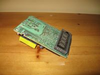
So after some unsoldering, examination of the circuit board and probing I discovered the pin-out of transformer and VFD, and shortly after had a 23V, 5V and filament voltage source along with a 5V TTL compatible VFD. The next step was to make the actual detectors, which consist of just an IR LED/phototransistor pair and comparator setup. That concluded the hardware, which left me with the programming part. After discovering the difficulty of division in assembly, I chose to program in Basic instead given some past experience with basic for PICs. MikroBasic Pro was used.
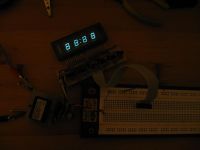
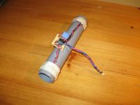
The program is rather simple, with the most complex portion being multiplexing the display. The program continously sends the value in the speed variable to the VFD. Interrupts on INT0 and 1 start the timer and stop it respectivly. INT1 interrupt also takes care of calculating the speed. Timer 0 is used and setup for 400kHz, giving 2.5µs resolution. Currently I coded it to read speeds from as low as 0.92m/s up to 594.06m/s before the precent error reaches 1%. Of course at closer to 600m/s consideration must be paid to the sensors themselves among other things, and 600m/s from a hobbyist coil gun is a bit optimistic.
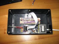
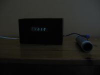
So there you have it! Fun to build, design, and use. I like doing "calm" projects once in while where nothing runs the risk of exploding. I'm disappointed with the VFD because it's much less intense than desired, and that I measured wrong when cutting out the display hole.
 (The dark hides it pretty well) The VFD was taken from garbage so I shouldn't be surprised. Other than that I'm satisfied with it.
EDIT: I've had to correct some serious errors in the code, but it's all sorted out now. The fixed .hex file can be found in my site.
Re: AVR Chronograph
rp181, Thu Jan 01 2009, 03:45PM
Nice useful project, but i must ask, why is the box so big? You should consider fitting the tube into the chrono so you shoot through the chrono :)
rp181, Thu Jan 01 2009, 03:45PM
Nice useful project, but i must ask, why is the box so big? You should consider fitting the tube into the chrono so you shoot through the chrono :)
Re: AVR Chronograph
uzzors2k, Fri Jan 02 2009, 06:15PM
Hehe, I bought the box a few weeks ago before I was sure of the size required. I hate having project boxes to big, but too small is even worse. I pulled out my coil gun to do some testing today, and I'm having extreme difficulty getting both sensors to trigger. I see the pro chronographs use some kind of large sensor window which would be excellent to have. It seems to me that they are optical, and must use the white plastic as a reflector. Anyone know how they work?
Re: AVR Chronograph
rp181, Fri Jan 02 2009, 06:31PM
In retail ones, both emitter and detector are at the bottom, the plastic is a reflector.
rp181, Fri Jan 02 2009, 06:31PM
In retail ones, both emitter and detector are at the bottom, the plastic is a reflector.
Re: AVR Chronograph
uzzors2k, Sat Jan 03 2009, 09:43PM
I moved the LEDs to the same side as the detectors and it seems to have a larger sensing area now. There were some serious flaws in the code. The Timer0 interrupt routine took longer than it's own overflow did, and there was no false trigger detector. Now the speed will default to zero if the first trigger is hit but not the second. The timer problem has been solved as well of course. Modifying the program in assembly for better efficiency could greatly improve the accuracy at high speeds, but I don't see the need to do so when only working with coil guns at sub 100m/s speeds. I tried it successfully on my old coil gun just now and the speeds correspond nicely to the expected values, so I assume everything is working as anticipated.
Re: AVR Chronograph
rp181, Sat Jan 03 2009, 09:45PM
Ive had sucess using a detector across from a emitter, with black heat shrink on both. resistance goes from several 100k down to less then 10k.
rp181, Sat Jan 03 2009, 09:45PM
Ive had sucess using a detector across from a emitter, with black heat shrink on both. resistance goes from several 100k down to less then 10k.
Re: AVR Chronograph
uzzors2k, Sun Jan 04 2009, 11:26AM
Didn't you have to hit both sensor beams though? That's the problem I had before, the beams were hard to hit in succession.
As for the code, I updated it one more time. This time I added some code to use the remainder in Timer0's register which in effect gives 50ns resolution. The error a sub 100m/s speeds is in the order of 0.01%.
Re: AVR Chronograph
rp181, Sun Jan 04 2009, 04:20PM
The fact that the PVC was white (i think) helped some. I also try to use as small diameter pipe as possible. You could make several of different diameters to swap out for different projectiles.
rp181, Sun Jan 04 2009, 04:20PM
The fact that the PVC was white (i think) helped some. I also try to use as small diameter pipe as possible. You could make several of different diameters to swap out for different projectiles.
Print this page