
Acrylic coilformer now finished. Comment.
ragnar, Wed Mar 29 2006, 11:46AMAs you may have seen me aspiring previously to high frequencies with high powers (fingers crossed with high reliability, HA!), I thought I'd make the first step in the right direction with a quality resonator.
Couple of problems with small, high-frequency resonators:
- the resonant frequency encourages short, thin resonators wound with thin wire.
- the thin wire will represent a relatively high resistance (skin effect) and gets hot,
- the former may catch fire
- the power throughput is limited
So I've designed a coilformer that will:
- significantly minimise the inter-turn capacitance,
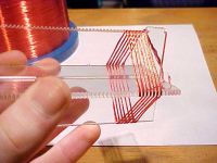
- facilitate the use of my own 19-strand x 0.15mm litz wire to give a nice low resistance for higher powers,
- not be in intimate contact with the windings, and allows forced/passive convection around the windings,
- offers a better (longer) tracking/flashover path, and dirt on the former won't be so much of an issue,
- more great stuff that I'm hoping people will add to this thread... :)
A few potential issues with the cross-section I've drawn, cut, and assembled are:
- the sharp corners might present an early breakdown point, perhaps I need a hexagonal or octagonal shape rather than square,
- more issues I'm hoping people will add to this thread... :D
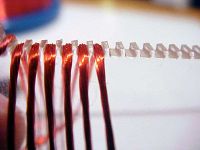
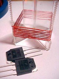
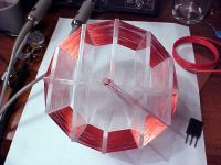
The former is made from lasercut 3mm acrylic sheet, slotted so the two can connect as seen below.
This was just a proof-of-concept, very rough. My planned dimensions are 20cm high, 7.5cm diameter, 100 turns (or an average of a turn every 2mm).
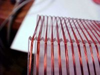
The final profile of the former's edge will be sawtooth not squarewave, which will encourage the litz wire to bunch up rather than flatten out.
I'm hoping to pump lots and lots of power through this lil fella at ~5MHz.
enjoy! =)
Criticism and suggestions welcome.
Pre-empting questions:
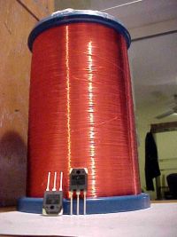
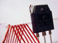
No, the 40N60 is only a gauge for size, it's got nothing to do with the former or the driver.
Yes, that's a 7KG roll of 0.15mm copper wire.
Re: Acrylic coilformer now finished. Comment.
WaveRider, Wed Mar 29 2006, 12:02PM
Hi BP,
At high frequencies, using thick winding wire will reduce winding losses. Litz wire may help, but remember that helical resonators with Q factors in the 100s can be constructed for freqs into the low microwave bands. These use fat windings. The losses are proportional to the product of effective wire diameter and the winding length whereas EM energy storage depends on the resonator volume. Since Q is proportional to Energy Storage/power loss per cycle, the best resonator performance is attained by maximising the ratio b/w effective resonator volume and wire length.
Of course there are tradeoffs when you want to maximise other things...like the length of your arcs.. Good luck!
Cheers!
Re: Acrylic coilformer now finished. Comment.
ragnar, Wed Mar 29 2006, 12:31PM
Dr Bill =)

interesting thinking about current density uniformity across the 19 windings and capacitance between the strands.
For a totally unrelated project, I made a C++ program; you specify a target inductance and the diameter of wire you're using, and it will calculate the ideal number of turns and the ideal diameter to achieve that inductance using the shortest length of wire... it suddenly occurred to me that the ratio between number of turns and coil diameter was a constant, and proportional to the thickness of wire! Silly me.
I find it very rewarding to be able to cross-fertilize knowledge/experience(/realisation of my own ignorance/stupidity) gained in one project with another.
In that case, I should redesign my former for the height to equal the diameter. Thanks very much indeed!
(click to enlarge)


ragnar, Wed Mar 29 2006, 12:31PM
Dr Bill =)
wrote ...
...At high frequencies, using thick winding wire will reduce winding losses. Litz wire may help, but remember that helical resonators with Q factors in the 100s can be constructed for freqs into the low microwave bands. These use fat windings...
I found this article (referred by SM) worthwhile consideration, too:...At high frequencies, using thick winding wire will reduce winding losses. Litz wire may help, but remember that helical resonators with Q factors in the 100s can be constructed for freqs into the low microwave bands. These use fat windings...

interesting thinking about current density uniformity across the 19 windings and capacitance between the strands.
wrote ...
...maximising the ratio b/w effective resonator volume and wire length...
In the case of the resonator, the best volume:wirelength ratio is where the height of the resonator is the diameter. I determined this empirically (and later found out on the web this is standard and expected) with a past project....maximising the ratio b/w effective resonator volume and wire length...
For a totally unrelated project, I made a C++ program; you specify a target inductance and the diameter of wire you're using, and it will calculate the ideal number of turns and the ideal diameter to achieve that inductance using the shortest length of wire... it suddenly occurred to me that the ratio between number of turns and coil diameter was a constant, and proportional to the thickness of wire! Silly me.
I find it very rewarding to be able to cross-fertilize knowledge/experience(/realisation of my own ignorance/stupidity) gained in one project with another.
In that case, I should redesign my former for the height to equal the diameter. Thanks very much indeed!
(click to enlarge)


Re: Acrylic coilformer now finished. Comment.
Marko, Fri Mar 31 2006, 06:30PM
I vote for single thick wire, it will be simpler to wind at least
With these frequencies you will end with more skin surface, silvered wire may also help if you can find some.
But now, turns are so spaced that your LC resonant frequency tends to be ultimately high, far away from 1/4wl frequency of helical resonator like this.
So we are back to what-is-a-tesla-coil again...
Marko, Fri Mar 31 2006, 06:30PM
I vote for single thick wire, it will be simpler to wind at least

With these frequencies you will end with more skin surface, silvered wire may also help if you can find some.
But now, turns are so spaced that your LC resonant frequency tends to be ultimately high, far away from 1/4wl frequency of helical resonator like this.
So we are back to what-is-a-tesla-coil again...
Re: Acrylic coilformer now finished. Comment.
Sulaiman, Fri Mar 31 2006, 10:07PM
From the little I've read
Tesla was very keen on optimising the Q of his resonators
but he wanted high voltage/charge operation
An arcing TC has such a low Q that close-wound is normally acceptable.
BTW, I think maximum Q for a single-layer solenoid is approx.
when radius=height, not diameter.
Re: Acrylic coilformer now finished. Comment.
Steve Conner, Sat Apr 01 2006, 10:03AM
It looks nice, but I bet it breaks out off the corners. If you can figure out a way to scale it up to make a cheap coil former that's like 7ft tall by 2ft diameter (without sharp corners) I give you 100 cookies and a big hug
Steve Conner, Sat Apr 01 2006, 10:03AM
It looks nice, but I bet it breaks out off the corners. If you can figure out a way to scale it up to make a cheap coil former that's like 7ft tall by 2ft diameter (without sharp corners) I give you 100 cookies and a big hug

Re: Acrylic coilformer now finished. Comment.
ragnar, Sat Apr 01 2006, 10:46AM
'evening Steve,
for lack of a good description, I'll rectify the sharp-corner-issue before cutting the next former, attached is a pic.
Even though the laser only has a bed of 600mm x 500mm, scaling up is just simple acrylic fabrication - make notches and joiners where you want to connect multiple segments.
As for the roundness issue, I'll use more perpendicular tiers to give a rounder cross-section.
Thanks for emphasising that potential issue before I make the thing =-)

Re: Acrylic coilformer now finished. Comment.
Desmogod, Sat Apr 01 2006, 01:49PM
After our conersation the other day, If you can make it, I reckon a hexagonal or octagonal former may be a better option for you.
I want one of those laser cutters!
Desmogod, Sat Apr 01 2006, 01:49PM
After our conersation the other day, If you can make it, I reckon a hexagonal or octagonal former may be a better option for you.
I want one of those laser cutters!
Re: Acrylic coilformer now finished. Comment.
ragnar, Sat Apr 01 2006, 02:22PM
And when you do get your lasercutter, then you'll have to learn how to use it. When things go wrong, you'll have to learn how to fix it. If the mirrors go out of alignment, you need to get in there and tweak it. When stuff catches fire, you have to extinguish it. When it needs regassing, you'll need to pay through the nose.
it's never as easy as it looks...
...but it's still my baby... *stroke*... *stroke*...
Just trying to calculate how many perpendicular iterations of this cross-section I should do.
5 looks about right... but still sharp corners... hrrm
Re: Acrylic coilformer now finished. Comment.
Marko, Sat Apr 01 2006, 02:34PM
Hi,
I think you can get the same using very thick wire with thickest possible insulation, and wind it around standard PVC tube.
For my 10Mhz resoantor (that what I still dont have driver for) I used telephone wire with thick insulaton, wire thickness is 0,5mm and af insulation about 0.4mm, so I have each two truns spaced for around 0,8mm total (or maybe even more since turns aren't absolutely tight).
But now you should absolutely use ths nice former, for try at least.
cheers...
Re: Acrylic coilformer now finished. Comment.
ragnar, Tue Apr 18 2006, 11:29AM
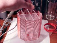
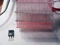
It is done;
100mm height, 100mm diameter, 50 turns. The geometry was neatly lasercut from 21cm x 24cm of clear 3mm acrylic.
Now all I've got to do is summon the courage to apply some power to the thing. After deciding where my coupling should start.
ragnar, Tue Apr 18 2006, 11:29AM
It is done;
100mm height, 100mm diameter, 50 turns. The geometry was neatly lasercut from 21cm x 24cm of clear 3mm acrylic.
Now all I've got to do is summon the courage to apply some power to the thing. After deciding where my coupling should start.


Re: Acrylic coilformer now finished. Comment.
..., Wed Apr 19 2006, 05:05AM
Well, lets see how much plasma you can make from a 50 turn secondary
I wonder if you will ever get to the point where you need forced air cooling inside...
I wonder if it would be worth the effort to create a similar former to build you primary on (using like 10 paralel strands of that litz wire) just to complete the whole floating wire look...
Things get interisting when the wire you used to wind your *secondary* is as big as the leads on your switches
Dare I suggest audiomodulation?
..., Wed Apr 19 2006, 05:05AM
Well, lets see how much plasma you can make from a 50 turn secondary

I wonder if you will ever get to the point where you need forced air cooling inside...
I wonder if it would be worth the effort to create a similar former to build you primary on (using like 10 paralel strands of that litz wire) just to complete the whole floating wire look...
Things get interisting when the wire you used to wind your *secondary* is as big as the leads on your switches

Dare I suggest audiomodulation?
Re: Acrylic coilformer now finished. Comment.
Desmogod, Wed Apr 19 2006, 05:10AM
Hehe, someone else has the same ideas.....
Very nice looking indeed.
Now to scale it to 10x40 inches.....
Desmogod, Wed Apr 19 2006, 05:10AM
... wrote ...
Dare I suggest audiomodulation?
Dare I suggest audiomodulation?
Hehe, someone else has the same ideas.....
Very nice looking indeed.
Now to scale it to 10x40 inches.....
Re: Acrylic coilformer now finished. Comment.
ragnar, Wed Apr 19 2006, 05:29AM
Audio modulation at that frequency with class-E topology? Tricky... ;)
I'm hoping this to be a scalable project, yes.
We'll see how much voltage rise I actually get from 50 turns...
did I mention improvements?
#1, next time I'll make all the cutouts/slots twice as deep,
#2, I should add some holes up the top for fastening electrode hardware and tying off the wire,
#3, as you said Peter (...), a floating primary to complete the look is absolutely necessary...
... now, how to do a floating primary with variable coupling.. muahaha
Thanks for checking it out guys.
More comments! Yes, you, reader! Tell me what you think =)
Re: Acrylic coilformer now finished. Comment.
Part Scavenger, Fri Apr 28 2006, 05:01PM
How about this?
Part Scavenger, Fri Apr 28 2006, 05:01PM
... wrote ...
I wonder if it would be worth the effort to create a similar former to build you primary on (using like 10 paralel strands of that litz wire) just to complete the whole floating wire look...
I wonder if it would be worth the effort to create a similar former to build you primary on (using like 10 paralel strands of that litz wire) just to complete the whole floating wire look...
How about this?
Print this page