Plasma speaker - flyback
Dr. H., Sun Dec 21 2008, 08:12AMGood guys
heres is yet ANOTHER plasma speaker

The circuit - from here

Thank you Dr. Kilovolt. I have made some changes to the circuit (mainly add filters and add a GDT driver).
For the flyback - I've tested a total of 6, and it turned out that an old bulgarian AC flyback - sounded best.
Power consumption - around 120W, the spark can be extended to around 3.5sm and it easily starts at 2.5sm. At lower frequencyes the spark increases up to 5 - 5.5sm but it sufferes from sound quallity ... badly.
Aboud the sound - I am trully amazed how well that thing sounds ... it sounds better than my laptop ( just weaker and it can't do the low freq range ... well)
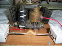
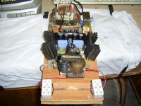
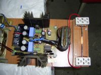
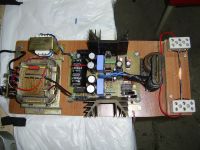
here some pics - what do you think ?
Cheers Dr. H.


Re: Plasma speaker - flyback
flannelhead, Sun Dec 21 2008, 10:37AM
That's a very nice and compact setup. Did you take those pics with flash? It makes the arc look pretty strange in the pictures.
flannelhead, Sun Dec 21 2008, 10:37AM
That's a very nice and compact setup. Did you take those pics with flash? It makes the arc look pretty strange in the pictures.
Re: Plasma speaker - flyback
Dr. H., Sun Dec 21 2008, 03:03PM
Good day sir
Yep - the pics were taken with flash, but in reallyty the arc isn't too different than that - it is yelow (what you see on the pic) with just a thin, barely visible, purple spark in the flame. The two tips of the tungsten electrodes are glowin in a very beautifull purple color (as it can be seen from the pics).
Cheers

Re: Plasma speaker - flyback
aonomus, Sun Dec 21 2008, 05:08PM
I've always wondered if the distortion whenever plasma speakers or audio modulated TC's attempt to play low frequency (sounds like sputtering) could be removed by using a lowpass filter so only mid-high plays and overall sound quality improves?
aonomus, Sun Dec 21 2008, 05:08PM
I've always wondered if the distortion whenever plasma speakers or audio modulated TC's attempt to play low frequency (sounds like sputtering) could be removed by using a lowpass filter so only mid-high plays and overall sound quality improves?
Re: Plasma speaker - flyback
Hon1nbo, Sun Dec 21 2008, 09:20PM
in that schematic, is the resistor below the 2.2K one (in the top image) a variable resistor connected like shown??? or is that an error?
I plan to put one of these together... with some modifications ^_0
Hon1nbo, Sun Dec 21 2008, 09:20PM
in that schematic, is the resistor below the 2.2K one (in the top image) a variable resistor connected like shown??? or is that an error?
I plan to put one of these together... with some modifications ^_0
Re: Plasma speaker - flyback
Dr. Dark Current, Sun Dec 21 2008, 10:22PM
Dr. H, nice speaker, cool to see someone build the circuit and it actually working
 ) have 3 legs, it really does not matter if you leave the 3rd leg floating or not, but for some reason I was in a strange mood and drew it the way I did (this is how it was drawn in old books in our country)
The obvious improvement is the use of gate drivers. I don't see any other modifications which could help.
Dr. Dark Current, Sun Dec 21 2008, 10:22PM
Dr. H, nice speaker, cool to see someone build the circuit and it actually working

DaJJHman wrote ...
in that schematic, is the resistor below the 2.2K one (in the top image) a variable resistor connected like shown??? or is that an error?
I plan to put one of these together... with some modifications ^_0
It is a standard "trimmer". They usually (well, almost always in that schematic, is the resistor below the 2.2K one (in the top image) a variable resistor connected like shown??? or is that an error?
I plan to put one of these together... with some modifications ^_0
 ) have 3 legs, it really does not matter if you leave the 3rd leg floating or not, but for some reason I was in a strange mood and drew it the way I did (this is how it was drawn in old books in our country)
The obvious improvement is the use of gate drivers. I don't see any other modifications which could help.
Re: Plasma speaker - flyback
Dr. H., Sun Dec 21 2008, 10:34PM
Good day guys
That is what I am also doing - a very basic first order high pas filter to get ride of the "low" freqs. About the values ... don't ask me - it was a tryal and error - and in the end I have a bunch of caps and resistors on the downside of the board
Dr. Kilovolt -> The obvious improvement is the use of gate drivers. I don't see any other modifications which could help.
Well that is what I also observed - without the drive chips, I coudn't go higher than 30-40khz - the fets were heating badly (the gate laveform was anything but good ) ... sooo adding the UCC now I am happily runing at 110khz and the fets are not heating at all, when no sound is played - ohh and that higher freq really makes a difference in the sound
Cheers
Dr. H., Sun Dec 21 2008, 10:34PM
Good day guys
aonomus wrote ...
I've always wondered if the distortion whenever plasma speakers or audio modulated TC's attempt to play low frequency (sounds like sputtering) could be removed by using a lowpass filter so only mid-high plays and overall sound quality improves?
I've always wondered if the distortion whenever plasma speakers or audio modulated TC's attempt to play low frequency (sounds like sputtering) could be removed by using a lowpass filter so only mid-high plays and overall sound quality improves?
That is what I am also doing - a very basic first order high pas filter to get ride of the "low" freqs. About the values ... don't ask me - it was a tryal and error - and in the end I have a bunch of caps and resistors on the downside of the board

Dr. Kilovolt -> The obvious improvement is the use of gate drivers. I don't see any other modifications which could help.
Well that is what I also observed - without the drive chips, I coudn't go higher than 30-40khz - the fets were heating badly (the gate laveform was anything but good ) ... sooo adding the UCC now I am happily runing at 110khz and the fets are not heating at all, when no sound is played - ohh and that higher freq really makes a difference in the sound

Cheers
Re: Plasma speaker - flyback
Hon1nbo, Mon Dec 22 2008, 02:31AM
yeah I know what they are, it is just that the image in the schematic looked kinda weird and I thought it might have been something else...
anyways, the mods I have planned are not of a serious design nature, but rather of a, how should I put this without giving everything away, selection of one component and using it to it's full potential?
Hon1nbo, Mon Dec 22 2008, 02:31AM
Dr. Kilovolt wrote ...
Dr. H, nice speaker, cool to see someone build the circuit and it actually working
 ) have 3 legs, it really does not matter if you leave the 3rd leg floating or not, but for some reason I was in a strange mood and drew it the way I did (this is how it was drawn in old books in our country)
The obvious improvement is the use of gate drivers. I don't see any other modifications which could help.
Dr. H, nice speaker, cool to see someone build the circuit and it actually working

DaJJHman wrote ...
in that schematic, is the resistor below the 2.2K one (in the top image) a variable resistor connected like shown??? or is that an error?
I plan to put one of these together... with some modifications ^_0
It is a standard "trimmer". They usually (well, almost always in that schematic, is the resistor below the 2.2K one (in the top image) a variable resistor connected like shown??? or is that an error?
I plan to put one of these together... with some modifications ^_0
 ) have 3 legs, it really does not matter if you leave the 3rd leg floating or not, but for some reason I was in a strange mood and drew it the way I did (this is how it was drawn in old books in our country)
The obvious improvement is the use of gate drivers. I don't see any other modifications which could help.
yeah I know what they are, it is just that the image in the schematic looked kinda weird and I thought it might have been something else...
anyways, the mods I have planned are not of a serious design nature, but rather of a, how should I put this without giving everything away, selection of one component and using it to it's full potential?
Re: Plasma speaker - flyback
Dr. Dark Current, Mon Dec 22 2008, 08:07AM
Dr. Dark Current, Mon Dec 22 2008, 08:07AM
Dr. H. wrote ...
Well that is what I also observed - without the drive chips, I coudn't go higher than 30-40khz - the fets were heating badly (the gate laveform was anything but good ) ... sooo adding the UCC now I am happily runing at 110khz and the fets are not heating at all, when no sound is played - ohh and that higher freq really makes a difference in the sound
Hmm, thats strange, it ran fine for me without the gate drivers just the gate waveform was a bit slow (but still good and resembled a square wave). Did you have the clamping diodes on the output?Well that is what I also observed - without the drive chips, I coudn't go higher than 30-40khz - the fets were heating badly (the gate laveform was anything but good ) ... sooo adding the UCC now I am happily runing at 110khz and the fets are not heating at all, when no sound is played - ohh and that higher freq really makes a difference in the sound

Re: Plasma speaker - flyback
Dr. H., Mon Dec 22 2008, 10:59AM
Good day sir
Yep - I've putted them (underneath the board if you are wondering where they are ).
).
Hey - this might be due to the IC I've used - there are many different manufacturers, and where I live and what the quallyty of parts is here - I wouldn't be surprised if it was made in some chinasee basement
Soo no problem if it doesn't work fine for me
But I reccomend drive chips - they will make the waveform much cleaner.
Cheers
Dr. H., Mon Dec 22 2008, 10:59AM
Good day sir
Dr. Kilovolt wrote ...
Hmm, thats strange, it ran fine for me without the gate drivers just the gate waveform was a bit slow (but still good and resembled a square wave). Did you have the clamping diodes on the output?
Hmm, thats strange, it ran fine for me without the gate drivers just the gate waveform was a bit slow (but still good and resembled a square wave). Did you have the clamping diodes on the output?
Yep - I've putted them (underneath the board if you are wondering where they are
 ).
). Hey - this might be due to the IC I've used - there are many different manufacturers, and where I live and what the quallyty of parts is here - I wouldn't be surprised if it was made in some chinasee basement

Soo no problem if it doesn't work fine for me
But I reccomend drive chips - they will make the waveform much cleaner.
Cheers
Print this page