
JimG's Smaller DRSSTC
JimG, Sun Feb 12 2006, 08:55AM9/20/2006
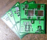
I just got these in today.
------------------------------
9/10/2006
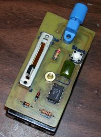
This weekend I built a dedicated optical interrupter for the second tiny DRSSTC. It uses a sliding variable resistor for an on time of 50-500us with a constant off time of 11ms.
------------------------------
7/11/2006
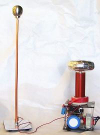
I built a ground target for the tiny DRSTTCs. I've been using it as a counterpoise so that I don't have to have a good ground to show off the coil.
The small size coil made it easy to take with me and show off during my July 4th vacation. It turned out to be very popular with children.
------------------------------
6/19/2006
I tried playing around with different break out points over the weekend and found that location and length drastically reduced the streamer length. With the reduced output the IGBTs would heat up very quickly, almost too hot to touch after only 3 or 4 seconds of run time.
Experiments with the interrupter timing have resulted in much thicker and brighter streamers. With the current timing I think I'm getting close to finishing up all of the tweaking I can do with this coil and will start cleaning up the wiring and build a dedicated external interrupter. If I find time I may rebuild the top load to something a little more presentable.
------------------------------
6/ 10/2006 Update:
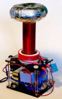
I've replaced the metal supports with acrylic rods and have added a small toroid. The total height is currently at 7.25 inches. This finishes up almost all of the hardware portion of this coil.
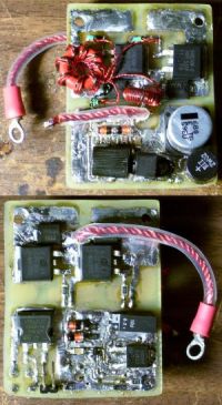
Here are photos of the front and back side of the controller board. The lower half of the board has the controller and the top half is the h-bridge. The board size is 2 1/2 x 1 3/4 inches.
------------------------------
6/1/2006 Update:
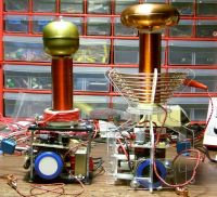
I'm getting close to finishing up my mains powered tiny DRSSTC coil. I stole the primary design from Steve since I couldn't think of anything better. It currently puts out 2 inch streamers and at least one 4.5 inch arc to ground with my variac set to 80 volts. Anything higher and it arcs from my ground connecter at the bottom of the secondary to my metal supports that hold up the coil platform. I also have my optical detector connected to the 12v power supply so it takes a lot longer to turn off than I would like. Hopefully I will get all of these bugs worked out soon.
The calculated Fres was 950 khz, but the measured Fres is 750 khz. I'm happy with that since I was aiming for a frequency lower than 1Mhz. Hopefully when I get a more permanent topload it won't change the resonance too much.
------------------------------
4/24/2006 Update:
I didn't want to start a new thread since this just feels like I'm making small changes to my previous design.
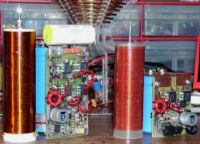
I wound a new secondary to be smaller and allow for a lower resonant frequency. My previous secondary had a 3.5" winding height and used #36(0.127mm) wire. My new secondary has a winding height of 3.0" and uses #40(0.08mm) wire.
My previous circuit board was 3 1/8" x 1 3/4" with an on-board interrupter. My new one is a 2 1/8" x 1 3/4" on a double sided board, with an external interrupter. I also switched away from using a dual 4A UCC27425 mosfet driver to a 9A UCC27321/UCC27322 pair.
I've also switched my capacitor over from using a 500uf cap to a 340uf one. Instead of charging it through a switch mode supply I plan to have this powered directly from mains using some sort of currently limiting.
I've finished building the circuit and done continuity testing, I just want to hook it up to a signal generator to make sure that the singal is propagating correctly before I do any smoke testing.
Picture of the old board and secondary sitting next to the new board and secondary:
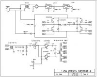
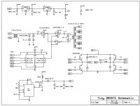
Schematic for the simplified board:
------------------------------
2/12/2006
Last October I was in a local surplus electronic parts store when I ran across a 1.375" x 3.5" 250V computer grade capacitor. Having just built two DRSSTCs I figured it might be cool to build a DRSSTC centered around this small capacitor. I then decided I would challenge myself with a few constraints.
1. The secondary shouldn't be any bigger than the capacitor.
2. The whole circuit should be kept small using SMT parts.
3. It should run off of a single power supply using a wall wart.
4. The interrupter should be on-board and easily updated.
5. It had to produce streamers, not just corona.
6. I wanted it to be a full bridge if possible.
On top of this I had never worked with SMT, I had never designed or etched a pcb, and I had never gotten either of my other two coils to work without flashing over with greater than 50 volts.
At home I found a small 1"x4" HDPE container similar to the vitamin C tube that I had seen others use and a small spool of 36 gauge wire. I figured that the unloaded coil would be about 2Mhz and loaded with run between 1.6Mhz and 1.8Mhz. At first I didn't think I would get anything to work based on the advice that I had read from a lot of people.
I chose to use a pic uc for my interrupter, direct feedback through a single schmitt trigger, a dual inverting/non-inverting mosfet driver and abstained from using any overcurrent, soft switching or dead-time circuity to keep everything very simple. I had my first circuit up and working toward the beginning of January using surface mount mosfets and a flat pancake primary with 6nf of primary capacitance. I experimented with a few GDT cores and found that a T50-2 gave me the best results.
This first test gave me very modest results with small 1/2" streamers. I figured I would need more current if I was going to go any bigger, but I had scoped the primary current at 40 amps and my mosfets were only rated for 14A. I almost gave up thinking that there was no way that I could get IGBTs to work at such a high frequency but decided to give it a shot anyway. To my amazement I could get a set of IGBTs to generate streamers just as long as the mosfets by tuning the primary circuit to a lower frequency.
At this point I figured it might be feasible to actually get this to produce some slightly larger streamers so I built a conical primary, added a toroid that I purchased from John Freau, increased the primary capacitance to 20nf, and set my on time to 75us. Once I had it together I set the interrupter to wait until the cap was up to about 175v before firing and applied power to the circuit. After about a second a bright white spark jumped one and a half inches from the break out point to a grounded target. I was very happy with the results and playing around with the tuning in that configuration I was able to get 4.5" ground strikes fairly easily and on occasion a 6" strike.
However, I still feel that I have a few things left to do.
* Right now the simple switch mode power supply that I've built can take a couple seconds to build up a sufficient charge for good sparks. I'm sure I can cut this down through some proper tuning.
* The primary current peaks out at about 200 amps. I think I can get some bigger sparks with shorter on times at these currents. Hopefully I can get shorter times between bursts if I can keep the main capacitor from fully discharging with each burst.
* I would like to experiment with different interrupter settings. I had pretty good success using a random number generator for random on and wait times on my larger DRSSTCs.
* The driver circuit will stop working after running for short periods and will start working a short time later. Everything is cool to the touch so I will need to investigate further into what is going wrong.
* Maybe I'll get a chance to revisit the circuit to add soft-switching.
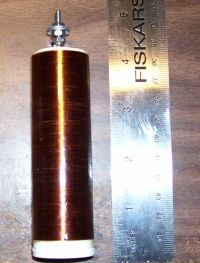
My secondary:
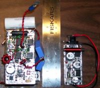
On the left is the h-bridge and controller, on the right is my 12v and 200v power supply:
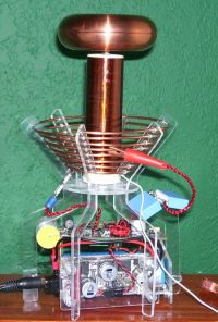
The final coil:
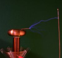
A 5" strike to a target 4 3/4" inches away:
Re: JimG's Smaller DRSSTC
craigsarea, Sun Feb 12 2006, 12:17PM
WOW . A great looking coil and great results. That really is a display piece
  .
.
The copper toroid looks really nice.
What IGBTs are you currently using?
Is your primary missing a strike ring? Does that matter?
Keep up the good work .
.
craigsarea, Sun Feb 12 2006, 12:17PM
WOW
 . A great looking coil and great results. That really is a display piece
  .
.The copper toroid looks really nice.
What IGBTs are you currently using?
Is your primary missing a strike ring? Does that matter?
Keep up the good work
 .
.Re: JimG's Smaller DRSSTC
JimG, Sun Feb 12 2006, 06:06PM
The IGBTs that I'm currently using are IRG4BC40WSs. I didn't put much thought into this since I half expected it to not work. I just wanted a high current IGBT in a D2Pak package. The fact that International Rectifier listed the speed as "warp" led me to believe that it would be about the fastest thing I could get in size I wanted.
When I was building the primary I didn't think I would get sparks long enough to require a strike ring so I didn't add one.
Re: JimG's Smaller DRSSTC
EEYORE, Sun Feb 12 2006, 08:05PM
Nice work!
Matt
EEYORE, Sun Feb 12 2006, 08:05PM
Nice work!
Matt
Re: JimG's Smaller DRSSTC
..., Sun Feb 12 2006, 08:23PM
Impressive, with all of these new drstc's coming out I may need to build one (right after the vttc I am working on and the pll sstc in the works...)
Can you give something for scale in the whole shot, like a coke can or something commonly recognizable? I am having trouble visualising the size of it after seeing all of the huge ones
What input power are you running? You said you were using a wall wort, does that imply like 20w
Keep up the good work!
..., Sun Feb 12 2006, 08:23PM
Impressive, with all of these new drstc's coming out I may need to build one (right after the vttc I am working on and the pll sstc in the works...)
Can you give something for scale in the whole shot, like a coke can or something commonly recognizable? I am having trouble visualising the size of it after seeing all of the huge ones

What input power are you running? You said you were using a wall wort, does that imply like 20w

Keep up the good work!
Re: JimG's Smaller DRSSTC
JimG, Sun Feb 12 2006, 08:37PM
Shot next to a Coke can.
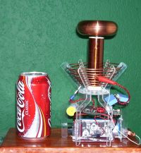
The wall wart is marked at 12VA. I have yet to get a reading from my Kill-A-Watt so I don't know how much it is actually drawing.
JimG, Sun Feb 12 2006, 08:37PM
Shot next to a Coke can.

The wall wart is marked at 12VA. I have yet to get a reading from my Kill-A-Watt so I don't know how much it is actually drawing.
Re: JimG's Smaller DRSSTC
Marko, Sun Feb 12 2006, 08:53PM
Im so sorry now for scrapping my small SGTC...
Wery nice jimG, really a tiny coil in proportions of large ones...
Marko, Sun Feb 12 2006, 08:53PM
Im so sorry now for scrapping my small SGTC...
Wery nice jimG, really a tiny coil in proportions of large ones...
Re: JimG's Smaller DRSSTC
HV Enthusiast, Sun Feb 12 2006, 09:54PM
Wow! That really is small. I love the photo of the coil putting out the arc to the ground rod. Looks almost like one of those old movies from the 1950's that used miniatures for special effects. Very cool!
Dan
HV Enthusiast, Sun Feb 12 2006, 09:54PM
Wow! That really is small. I love the photo of the coil putting out the arc to the ground rod. Looks almost like one of those old movies from the 1950's that used miniatures for special effects. Very cool!
Dan
Re: JimG's Smaller DRSSTC
JimG, Sun Feb 19 2006, 06:49AM
Update:
I changed my bleed resistor from a 27K to a 330K and set my SMPS duty cycle from 50% to 90%. This decreased the charge time on the main capacitor and increased the reliability of the overall circuit. I measured the power out of the wall at 30W with this new setup. I should be able to lower my off time between bursts since I'm charging much faster now.
12 second exposure to ground:
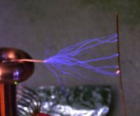
12 second streamer exposure:

Energy transfer doesn't seem to be very good, though. The primary current peaks at around 4us, but doesn't drop off very fast. I built the secondary support to make it easy to change the coupling, but I currently have it about as high as I can get it.
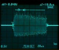
Each vertical division represents 50A and each horizontal division represents 20us.
JimG, Sun Feb 19 2006, 06:49AM
Update:
I changed my bleed resistor from a 27K to a 330K and set my SMPS duty cycle from 50% to 90%. This decreased the charge time on the main capacitor and increased the reliability of the overall circuit. I measured the power out of the wall at 30W with this new setup. I should be able to lower my off time between bursts since I'm charging much faster now.
12 second exposure to ground:

12 second streamer exposure:

Energy transfer doesn't seem to be very good, though. The primary current peaks at around 4us, but doesn't drop off very fast. I built the secondary support to make it easy to change the coupling, but I currently have it about as high as I can get it.

Each vertical division represents 50A and each horizontal division represents 20us.
Re: JimG's Smaller DRSSTC
..., Sun Feb 19 2006, 07:21AM
WOW, that is tiny!
And 6" off 12w That is the best efficiency I have ever seen! My 20w sgtc got about 6mm
  To get 6" of my vttc takes >1kw
Have you published the schematics anywhere?
..., Sun Feb 19 2006, 07:21AM
WOW, that is tiny!
And 6" off 12w
 That is the best efficiency I have ever seen! My 20w sgtc got about 6mm
  To get 6" of my vttc takes >1kw
Have you published the schematics anywhere?
Re: JimG's Smaller DRSSTC
JimG, Sun Feb 19 2006, 10:37AM
To be fair, it peaks at 30W after a burst and drops to 8W before a burst. The 6" strike was after it had charged for 2.5 seconds. The rate is currently set to 1 burst per second with 5" strikes. I think if I had a better primary that I could get more efficiency.
This is the schematic as it currently stands. The bad thing about it is that the power supply isn't regulated.

Re: JimG's Smaller DRSSTC
hilo90mhz, Sat Mar 25 2006, 08:57AM
200A peak in a coil that small!! amazing! good work
hilo90mhz, Sat Mar 25 2006, 08:57AM
200A peak in a coil that small!! amazing! good work
Re: JimG's Smaller DRSSTC
Steve Conner, Sat Mar 25 2006, 10:25AM
Yea, at over 1MHz too! I think the coolest thing is that it's actually powered off a wall wart and still manages 5-6" sparks. Way to go JimG!
BTW: Pulsed SSTCs can give a very high "Efficiency" in terms of inches of spark out per watt in, just by operating at a very low breakrate. In the limit, you could make a giant DRSSTC, spend a whole afternoon charging its DC bus cap bank off a 9v battery with a tiny DC-DC converter (even a small battery contains hundreds of joules) and then release all the energy in a few milliseconds to produce a giant 10 foot arc. Then you could truthfully claim you got a 10 foot arc out of a 9v battery and a 3 watt DC-DC converter.
This is considered cheating though: if you want to play at high efficiency, you have to measure it in the steady state at 100-120 discharges per second. The reason for choosing this breakrate is that John Freau used 120 in his original experiments on efficiency.
Steve Conner, Sat Mar 25 2006, 10:25AM
Yea, at over 1MHz too!
 I think the coolest thing is that it's actually powered off a wall wart and still manages 5-6" sparks. Way to go JimG!
BTW: Pulsed SSTCs can give a very high "Efficiency" in terms of inches of spark out per watt in, just by operating at a very low breakrate. In the limit, you could make a giant DRSSTC, spend a whole afternoon charging its DC bus cap bank off a 9v battery with a tiny DC-DC converter (even a small battery contains hundreds of joules) and then release all the energy in a few milliseconds to produce a giant 10 foot arc. Then you could truthfully claim you got a 10 foot arc out of a 9v battery and a 3 watt DC-DC converter.
This is considered cheating though: if you want to play at high efficiency, you have to measure it in the steady state at 100-120 discharges per second. The reason for choosing this breakrate is that John Freau used 120 in his original experiments on efficiency.
Re: JimG's Smaller DRSSTC
Omicron, Sat Mar 25 2006, 05:34PM
Are the computer caps the same one sold at the electronics gold mine?
Omicron, Sat Mar 25 2006, 05:34PM
Are the computer caps the same one sold at the electronics gold mine?
Re: JimG's Smaller DRSSTC
JimG, Sat Mar 25 2006, 07:13PM
I didn't want to boast about the power usage too much because when running at 100 bps it only produces 1/2" streamers and 1" sparks.
When doing the longer sparks the cap drains within a few bursts. The mosfet drivers will almost completely drain my supply capacitors and it could take about a quarter second before the switch mode power supply starts fully working again. It's an issue with using a single 12VA wall wart to power both sections of the circuit.
No, I got the cap from a local electronics parts surplus store.
I've started winding a lower frequency secondary and figured I could cut my circuit board length in half by going with a two layer bridge. The EG cap may be a good fit to make a smaller controller.
JimG, Sat Mar 25 2006, 07:13PM
Steve Conner wrote ...
This is considered cheating though: if you want to play at high efficiency, you have to measure it in the steady state at 100-120 discharges per second. The reason for choosing this breakrate is that John Freau used 120 in his original experiments on efficiency.
This is considered cheating though: if you want to play at high efficiency, you have to measure it in the steady state at 100-120 discharges per second. The reason for choosing this breakrate is that John Freau used 120 in his original experiments on efficiency.
I didn't want to boast about the power usage too much because when running at 100 bps it only produces 1/2" streamers and 1" sparks.
When doing the longer sparks the cap drains within a few bursts. The mosfet drivers will almost completely drain my supply capacitors and it could take about a quarter second before the switch mode power supply starts fully working again. It's an issue with using a single 12VA wall wart to power both sections of the circuit.
Omicron wrote ...
Are the computer caps the same one sold at the electronics gold mine?
Are the computer caps the same one sold at the electronics gold mine?
No, I got the cap from a local electronics parts surplus store.
I've started winding a lower frequency secondary and figured I could cut my circuit board length in half by going with a two layer bridge. The EG cap may be a good fit to make a smaller controller.
Re: JimG's Smaller DRSSTC
JimmyH, Sun Apr 09 2006, 09:34PM
First of all, I must say that I am impressed. The first time I saw it, I thought it was bigger than that, and just another 'little' DRSSTC.
There are a few things I don't get though. The most important one, is why did you step the voltage down to 12v with a wall wart, and then step it back up for the IGBTs, instead of just rectifying mains? A single diode could easily supply more power at 170v. Then you could turn up the break rate a bit, and make it even cooler.
You said that you learned that tuning the primary low, you could get the same results with IGBTs as with MOSFETs (detuning is a cool trick, huh?). How much lower are you talking about? What is the driving frequency vs the secondary resonance frequency?
I think you can push this thing harder! Step up the voltage more, and see what it's capable of!
Re: JimG's Smaller DRSSTC
JimG, Mon Apr 10 2006, 05:14AM
I went with the wall wart because I wanted to be in close proximity to the coil while I poked around with it and not have live mains. It would have been a better accomplishment if I didn't have to sacrifice a fast break rate for long streamers. The next coil I build will definitely not be powered this way.
The drop in fequency wasn't much, ~1.4Mhz down to ~1.3Mhz. I not sure of the exact frequency since I eyeballed it with a scope. With the new top load the caculated resonance is 1.17Mhz, but I'm running closer to 1.10 Mhz.
I've noticed that I'm getting no notches in my waveform off of the primary coil, my larger DRSSTC would get them after 10 to 15 cycles. Is this common with de-tuning, or is a symptom of low coupling?
I have a lower frequency coil wound and I've started designing a new circuit with better gate drivers. The coil I have now has an unloaded frequency frequency of 1.98 Mhz and the new one is 1.55Mhz and is a half inch shorter. I've decided to leave the current coil as a show piece and really push it with the new coil.
JimG, Mon Apr 10 2006, 05:14AM
JimmyH wrote ...
There are a few things I don't get though. The most important one, is why did you step the voltage down to 12v with a wall wart, and then step it back up for the IGBTs, instead of just rectifying mains? A single diode could easily supply more power at 170v. Then you could turn up the break rate a bit, and make it even cooler.
There are a few things I don't get though. The most important one, is why did you step the voltage down to 12v with a wall wart, and then step it back up for the IGBTs, instead of just rectifying mains? A single diode could easily supply more power at 170v. Then you could turn up the break rate a bit, and make it even cooler.
I went with the wall wart because I wanted to be in close proximity to the coil while I poked around with it and not have live mains. It would have been a better accomplishment if I didn't have to sacrifice a fast break rate for long streamers. The next coil I build will definitely not be powered this way.
JimmyH wrote ...
You said that you learned that tuning the primary low, you could get the same results with IGBTs as with MOSFETs (detuning is a cool trick, huh?). How much lower are you talking about? What is the driving frequency vs the secondary resonance frequency?
You said that you learned that tuning the primary low, you could get the same results with IGBTs as with MOSFETs (detuning is a cool trick, huh?). How much lower are you talking about? What is the driving frequency vs the secondary resonance frequency?
The drop in fequency wasn't much, ~1.4Mhz down to ~1.3Mhz. I not sure of the exact frequency since I eyeballed it with a scope. With the new top load the caculated resonance is 1.17Mhz, but I'm running closer to 1.10 Mhz.
I've noticed that I'm getting no notches in my waveform off of the primary coil, my larger DRSSTC would get them after 10 to 15 cycles. Is this common with de-tuning, or is a symptom of low coupling?
JimmyH wrote ...
I think you can push this thing harder! Step up the voltage more, and see what it's capable of!
I think you can push this thing harder! Step up the voltage more, and see what it's capable of!
I have a lower frequency coil wound and I've started designing a new circuit with better gate drivers. The coil I have now has an unloaded frequency frequency of 1.98 Mhz and the new one is 1.55Mhz and is a half inch shorter. I've decided to leave the current coil as a show piece and really push it with the new coil.
Re: JimG's Smaller DRSSTC
JimmyH, Mon Apr 10 2006, 06:40AM
Well, if you're gonna do another one, putting a fat 10kohm resistor in series could give you the same effect while you test it out.
Ok, I wasnt sure if you were just driving the crap out of it at 500khz, or something
rediculously low.
Yeah, that tends to come with detuning, but low coupling would also reduce the notching. If you're worried about coupling, javatc can probably give you a better number than you can measure :P
Ok, cool. As long as you push the new one . Steve Ward and I are thinking of making tiny (DR)SSTCs, so if you want to keep your recognition of owning "the most badass tiny SSTC", then don't slack on the new one!
Good luck!
JimmyH, Mon Apr 10 2006, 06:40AM
I went with the wall wart because I wanted to be in close proximity to the coil while I poked around with it and not have live mains. It would have been a better accomplishment if I didn't have to sacrifice a fast break rate for long streamers. The next coil I build will definitely not be powered this way.
Well, if you're gonna do another one, putting a fat 10kohm resistor in series could give you the same effect while you test it out.
The drop in fequency wasn't much, ~1.4Mhz down to ~1.3Mhz. I not sure of the exact frequency since I eyeballed it with a scope. With the new top load the caculated resonance is 1.17Mhz, but I'm running closer to 1.10 Mhz.
Ok, I wasnt sure if you were just driving the crap out of it at 500khz, or something
rediculously low.
I've noticed that I'm getting no notches in my waveform off of the primary coil, my larger DRSSTC would get them after 10 to 15 cycles. Is this common with de-tuning, or is a symptom of low coupling?
Yeah, that tends to come with detuning, but low coupling would also reduce the notching. If you're worried about coupling, javatc can probably give you a better number than you can measure :P
I have a lower frequency coil wound and I've started designing a new circuit with better gate drivers. The coil I have now has an unloaded frequency frequency of 1.98 Mhz and the new one is 1.55Mhz and is a half inch shorter. I've decided to leave the current coil as a show piece and really push it with the new coil.
Ok, cool. As long as you push the new one
 . Steve Ward and I are thinking of making tiny (DR)SSTCs, so if you want to keep your recognition of owning "the most badass tiny SSTC", then don't slack on the new one!
Good luck!
Re: JimG's Smaller DRSSTC
JimG, Mon Apr 10 2006, 02:58PM
I wasn't expecting any kind of competition. I guess I will need to stay on my toes with this next one.
I tried going with a lower harmonic, but it didn't work very well. I didn't try to push more power through it than I had at resonance, though.
JimG, Mon Apr 10 2006, 02:58PM
I wasn't expecting any kind of competition. I guess I will need to stay on my toes with this next one.
Ok, I wasnt sure if you were just driving the crap out of it at 500khz, or something
rediculously low.
I tried going with a lower harmonic, but it didn't work very well. I didn't try to push more power through it than I had at resonance, though.
Re: JimG's Smaller DRSSTC
JimG, Mon Apr 24 2006, 05:41AM
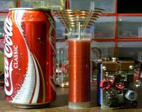
Update with new board and secondary.
obligatory coke can shot of the new coil and board
JimG, Mon Apr 24 2006, 05:41AM
Update with new board and secondary.
obligatory coke can shot of the new coil and board

Re: JimG's Smaller DRSSTC
Bennem, Mon Apr 24 2006, 07:56AM
Wow!
Now that IS tiny!
I'm putting together a tiny DRSSTC, but in comparison, mines huge!.....lol
Here's my driver and combined H-bridge of HGT1N40N60A4D's
All the best with your project!
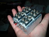
Bennem, Mon Apr 24 2006, 07:56AM
Wow!
Now that IS tiny!
I'm putting together a tiny DRSSTC, but in comparison, mines huge!.....lol
Here's my driver and combined H-bridge of HGT1N40N60A4D's
All the best with your project!


Re: JimG's Smaller DRSSTC
EEYORE, Mon Apr 24 2006, 11:44AM
Wow, nice work guys!
Better keep the on time really low for that full bridge!Ive never seen 40n60s made into such a small full bridge...
Now im getting the mini bug!
Matt
EEYORE, Mon Apr 24 2006, 11:44AM
Wow, nice work guys!
Better keep the on time really low for that full bridge!Ive never seen 40n60s made into such a small full bridge...
Now im getting the mini bug!
Matt
Re: JimG's Smaller DRSSTC
Steve Ward, Sat May 27 2006, 02:20AM
Ive got some results to report now as well. This was inspired by Jims work of course. The secondary is 1.3"x3", with a 1"x3" (roughly) toroid. Im using FGH50N6S2D IGBTs from fairchild in a half-bridge. My driver is the simplest i could do, just a pair of gate drivers (UCC27321/2). The feedback CT (primary feedback) is fed through a .1u cap, then clamped to the power rails with some 1n4148 diodes. The interrupter plugs right into the enable pins. The GDT is 1:2:2, using 6 primary turns and 12 secondary turns. The tank cap is 9.2nF at the moment. The primary coil is on 2.375" diameter pipe, 5.5 turns. The operating frequency is around 1.2MHz. Sparks reach out to 7" pretty regularly. Im running very long pulse widths, of up to 1mS. Anyway, i dont want to take over this thread, but since its a very similar project, i figured id make a post about it.
Pictures will be held in this folder, and may be updated as progress continues:
link
Re: JimG's Smaller DRSSTC
ragnar, Sat May 27 2006, 05:16AM
Aw Steve, that's just adorable. Love the protoboard and the primary, too.
ragnar, Sat May 27 2006, 05:16AM
Aw Steve, that's just adorable. Love the protoboard and the primary, too.
Re: JimG's Smaller DRSSTC
JimG, Sat May 27 2006, 04:29PM
Cool small coil, Steve. I've been a bit leery about going over 100us for fear of burning out my tiny IGBTs, but after seeing your long pulse sparks I've been curious how long of a pulse I can do with the small capacitors that I'm using.
I've been doing a bit of overtime at work so I haven't had a chance to work on my mains powered tiny coil. Hopefully I'll have enough time this weekend to finish it.
Re: JimG's Smaller DRSSTC
Steve Conner, Sat May 27 2006, 04:47PM
OMG, invasion of the mini DRSSTCs. :-o Steve, the streamers from yours look almost like VTTC sword streamers but not quite. Could you rig it to fire half-cycles of unsmoothed AC line with a staccato timer type circuit, and see if the streamers turn straight?
Steve Conner, Sat May 27 2006, 04:47PM
OMG, invasion of the mini DRSSTCs. :-o Steve, the streamers from yours look almost like VTTC sword streamers but not quite. Could you rig it to fire half-cycles of unsmoothed AC line with a staccato timer type circuit, and see if the streamers turn straight?
Re: JimG's Smaller DRSSTC
JimG, Sun Jun 04 2006, 05:32PM
My camera isn't sensitive enough to get spark pictures off of this coil so I've attached a video of the sparks. It's not quite up to where Steve's coil is, though, but I'm still tuning it.
I'll try to post an update later today.
]1149442005_52_FT600_tnydrsstc2sparks.wmv[/file]
Composite image taken from video stills.
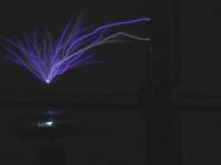
Even with the changes I've made I'm still getting flashovers at higher voltages. Hopefully I can fix this without changing any hardware by adding a feature to my interrupter re-write that will increase the on times for a single burst to promote streamer growth from the breakout point.
My tiny IGBTs aren't heatsinked so they get a little warm to the touch after a few minutes of running. Hopefully allowing for shorter on times and longer delays will help keep them a little cooler.
JimG, Sun Jun 04 2006, 05:32PM
My camera isn't sensitive enough to get spark pictures off of this coil so I've attached a video of the sparks. It's not quite up to where Steve's coil is, though, but I'm still tuning it.
I'll try to post an update later today.
]1149442005_52_FT600_tnydrsstc2sparks.wmv[/file]
Composite image taken from video stills.

Even with the changes I've made I'm still getting flashovers at higher voltages. Hopefully I can fix this without changing any hardware by adding a feature to my interrupter re-write that will increase the on times for a single burst to promote streamer growth from the breakout point.
My tiny IGBTs aren't heatsinked so they get a little warm to the touch after a few minutes of running. Hopefully allowing for shorter on times and longer delays will help keep them a little cooler.
Re: JimG's Smaller DRSSTC
JimG, Mon Jun 12 2006, 05:47AM
I've modified my old interrupter to do three 40us on/50us off pulses and then a 200us pulse. I can now crank my variac all the way up to its max rating of 130V with no flashovers to the primary. The streamers are also a lot brighter now.
Photo with variac set to 100v with 4.25 inch arcs to ground, 2 second exposure.
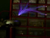
Photo with the variac set to 120V with a streamer reaching out to 6 inches, 1.5 second exposure.
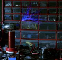
Steve, I don't think I'm going to make it out to 7" like you did without a bit more work. Interrupter timing seems to be pretty critical to the streamer performance more than the voltage since I can get better streamers now at 80V than I could with the old settings at a little over 100V.
During a few test runs I measured the voltage in my 350 uF supply capacitor. It starts off at 176V and drops to 106V after a single shot, so I'm sure I can squeeze a little more out of it.
JimG, Mon Jun 12 2006, 05:47AM
I've modified my old interrupter to do three 40us on/50us off pulses and then a 200us pulse. I can now crank my variac all the way up to its max rating of 130V with no flashovers to the primary. The streamers are also a lot brighter now.
Photo with variac set to 100v with 4.25 inch arcs to ground, 2 second exposure.

Photo with the variac set to 120V with a streamer reaching out to 6 inches, 1.5 second exposure.

Steve, I don't think I'm going to make it out to 7" like you did without a bit more work. Interrupter timing seems to be pretty critical to the streamer performance more than the voltage since I can get better streamers now at 80V than I could with the old settings at a little over 100V.
During a few test runs I measured the voltage in my 350 uF supply capacitor. It starts off at 176V and drops to 106V after a single shot, so I'm sure I can squeeze a little more out of it.
Re: JimG's Smaller DRSSTC
Steve Ward, Mon Jun 12 2006, 07:30AM
Hey Jim,
The only way i could get the 7" sparks was with the really long pulse lengths of at least 250uS. Anything that would seem resonable for a tiny DRSSTC (say 10-50uS) wasnt enough for maybe 2" sparks. Also, im running 350VDC on the half-bridge, so that may also give me an edge. Im not sure what i want to try next with my mini... maybe a larger tank C and less L. Im running 100A peak right now which is pretty safe, so maybe i should just leave it alone. Unfortunately, i cant run much more than 10bps before the IGBTs get really hot . Perhaps a better cooling system would be a nice upgrade.
At Conner: i might try a half-wave voltage doubler to see if i can get straighter sparks. It could possibly be really cool.
Im still working on how to package the little guy... I want to keep it as small as possible.
Steve Ward, Mon Jun 12 2006, 07:30AM
Hey Jim,
The only way i could get the 7" sparks was with the really long pulse lengths of at least 250uS. Anything that would seem resonable for a tiny DRSSTC (say 10-50uS) wasnt enough for maybe 2" sparks. Also, im running 350VDC on the half-bridge, so that may also give me an edge. Im not sure what i want to try next with my mini... maybe a larger tank C and less L. Im running 100A peak right now which is pretty safe, so maybe i should just leave it alone. Unfortunately, i cant run much more than 10bps before the IGBTs get really hot
 . Perhaps a better cooling system would be a nice upgrade.
At Conner: i might try a half-wave voltage doubler to see if i can get straighter sparks. It could possibly be really cool.
Im still working on how to package the little guy... I want to keep it as small as possible.
Re: JimG's Smaller DRSSTC
JimG, Mon Jun 12 2006, 05:55PM
I figure 170V DC on my full-bridge should be almost equivalent to 350V DC on your half-bridge. I went with a full bridge because the IBGTs take up less space than a second capacitor.
On my previous coil I certainly saw an increase in the streamer length when I went from 7.5nF to 20nF for my tank cap and measured about 100 Amps in the circuit. I haven't measured the current on the current one using a 22nF cap, but I'll probably do that tonight.
I have been a little concerned with overheating on this coil since I decided to put the IGBTs back to back on the board to cut down on space while the previous one had a small heat sink epoxied behind the IGBTs. I've been thinking about using some thermal epoxy to affix some sort of ceramic heatsinks to IGBT bodies, but haven't started looking into it yet.
I can't wait to see how you coil turns out, Steve. Your DRSSTC.5 was part of the inspiration for me to want to make a DRSSTC using a very small
capacitor.
Update:
I've had a chance to measure the current and it seems to average somewhere between 100 and 150 Amps. There are a few cycles where the current spikes to between 200 and 240 Amps.
Print this page