Copper Clad Thickness Probe
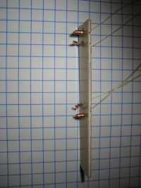
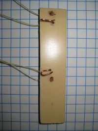
..., Sat Jul 26 2008, 07:53AMI ended up with a big pile of random PCBs and needed a way to measure the thickness of the copper clad. After a little headscratching I came up with this dodad:


You hook a current source across the 2 thick pins, and a voltmeter across the 2 thin springy pins, and press it against the board. Run about 1.5a (or .15a if you have a good voltmeter that will read to microvolts) current through the board, and note the output voltage. It is inversely proportional the the copper thickness! It works really well too, I went through a stack of 20 boards in 5 minutes and sorted them into .5oz 1oz 2oz.
check out the webpage for more info
Re: Copper Clad Thickness Probe
Shaun, Sat Jul 26 2008, 02:36PM
So for this to work all the pieces you test must be the same width and have the same electrode spacing, right? I only ask because I have some PCBs whose thickness I do not know.
Shaun, Sat Jul 26 2008, 02:36PM
So for this to work all the pieces you test must be the same width and have the same electrode spacing, right? I only ask because I have some PCBs whose thickness I do not know.
Re: Copper Clad Thickness Probe
..., Sat Jul 26 2008, 04:20PM
No, the electrode spacing is kept constant by the probes design. As long as there is an area of copper free of holes/cuts/etc that is larger than the probe you should be good to go. You will get the best results if you have >2" of copper surrounding the probe on all sides, but it will work just fine as long as there is a free area of copper large enough to cover all of the contacts, the reading will be a little high.
Print this page