
Induction heater (featuring my new PLL driver  )
)
uzzors2k, Sat Jul 12 2008, 07:05PM
Originally I just bought a bunch of el-cheapo foil caps from ebay on impulse with the intention of trying the LCLR topology again. It worked somewhat with a simple TL494 inverter, but I had to constantly adjust the frequency by hand to keep the capacitor voltage safe or current draw under control. All it would have taken was one slip and the bridge or tank capacitor would die. Meh. And I hadn't even gotten to tuning the matching inductor yet.
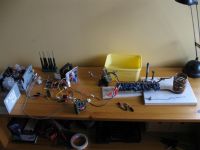
So I started designing a driver based on frequency adjustment to regulate the tank voltage, inverter current or inverter/tank phase. Which ever had the highest priority. (The discussion took place silently in this thread.) It would be nothing new actually, as this type of driver has been done before only with discretes.
 Tim's IH is complicated as hell though, and I wasn't going for something that elaborate. So after many different versions I eventually got something which worked and was reasonably simple. Behold.
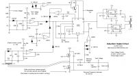
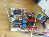
As Richie has detailed on his site the LCLR arrangement presents a capacitive load below resonance and inductive above resonance, with inductive reactance being the most forgiving for a square wave inverter. Therefor an increase in supply current or tank voltage brings the VCO frequency up. On either side of resonance the impedance of the LCLR circuit increases, lowering current draw and resonant rise. With low supply voltages or proper loads neither the tank voltage nor the inverter current will need regulation, in which case the driver must lock onto the exact resonant frequency of the LCLR circuit for max efficiency and power. The PLL takes care of this by adjusting the VCO frequency to the point where the inverter output and tank voltage are 90 degrees out of phase (inverter leading the tank voltage), because this phase difference characterizes resonance in a LCLR circuit.
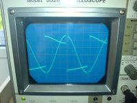
How does it work in the real world? Excellently. With light to no load the voltage or current protection kicks in and keeps the inverter from self destructing. With moderate to heavy loads the PLL kicks in and keeps everything in resonance. I've run it several times over the last few weeks and haven't noticed any odd behaviour yet. The only thing I dislike is that the voltage/current regulation isn't "smooth" but seems to oscillate somewhat. It's hard to explain but you can hear white noise whenever the regulation kicks in. Hasn't caused any noticeable problems though.
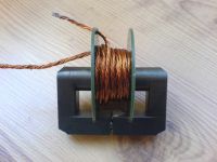
Anyway with the new driver finally done I can continue working on the LCLR topology. Atm I've narrowed the limiting factor down to the matching inductor which heats up fast. Before I can do any serious heating I need to make something more robust. Currently the inductor sports 16-filar 0.3mm litz wire, which I thought would be good for 20A at 100kHz. Hence the surprise when it started heating so badly. Is there nothing more to do than wind more litz wire or get copper strips? How does one make a power inductor?
Re: Induction heater (featuring my new PLL driver  )
)
Firefox, Sat Jul 12 2008, 08:24PM
I don't know if this is practical, but you could cut some Al flashing into a proper width strip, and turn your matching inductor from that. As I understand it, Aluminum has a larger skin depth than copper, so it may be better in this situation, and the surface area will effectively give you a larger conducting area. Also, the windings may have enough surface area to dissipate generated heat better than the 16 filar litz wire you have.
 )
)Firefox, Sat Jul 12 2008, 08:24PM
I don't know if this is practical, but you could cut some Al flashing into a proper width strip, and turn your matching inductor from that. As I understand it, Aluminum has a larger skin depth than copper, so it may be better in this situation, and the surface area will effectively give you a larger conducting area. Also, the windings may have enough surface area to dissipate generated heat better than the 16 filar litz wire you have.
Re: Induction heater (featuring my new PLL driver  )
)
GeordieBoy, Sat Jul 12 2008, 08:33PM
Sounds good Uzzors - I'm glad you got the controller working well.
The noise you noticed during current-limiting could be due to instability in the current control loop. Or it might be the sign of a potentially damaging low-frequency resonance between the bridge's DC blocking capacitor and the Lmatch inductor. (The DC blocking cap and Lmatch inductor will series resonate at a lowish frequency. Any control loop oscillation around this frequency is BAD!)
Re: Power inductor design, i'd use a large Mn/Zn ferrite E-core set, gapped and wound with litz. ETD and EC cores are designed to minimise the mean turn length and volume of ferrite, which is fine for a transformer, but it is not really what is wanted here. Power electronics books should cover the magnetics design.
-Richie,
 )
)GeordieBoy, Sat Jul 12 2008, 08:33PM
Sounds good Uzzors - I'm glad you got the controller working well.
The noise you noticed during current-limiting could be due to instability in the current control loop. Or it might be the sign of a potentially damaging low-frequency resonance between the bridge's DC blocking capacitor and the Lmatch inductor. (The DC blocking cap and Lmatch inductor will series resonate at a lowish frequency. Any control loop oscillation around this frequency is BAD!)
Re: Power inductor design, i'd use a large Mn/Zn ferrite E-core set, gapped and wound with litz. ETD and EC cores are designed to minimise the mean turn length and volume of ferrite, which is fine for a transformer, but it is not really what is wanted here. Power electronics books should cover the magnetics design.
-Richie,
Re: Induction heater (featuring my new PLL driver  )
)
uzzors2k, Sun Jul 20 2008, 08:42AM
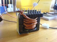
I decided to make another 16-filar litz wire and wind it bifilar with the old one. About two meters of 32 strands of 0.3mm wire, wrapped around the second largest core I have. It's DC resistance is only 8.5mΩ, so it shouldn't dissipate more than a few watts.
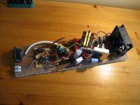
I also doubled up the IRFP450s which reduced power dissipation considerably. With a single fan the inverter can run continuously I believe. Now if only the tank could do the same. The capacitors don't get warm themselves, which isn't bad considering how cheap they were. They do heat up from the immense heat conducted by the work coil though, an insulating crucible would help.
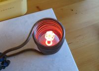
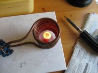
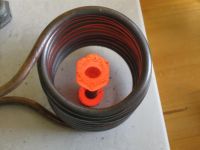
And some mandatory pics of redhot iron. The power of this IH isn't very impressive IMO, but at least it worked as a test bed for my new driver.
 )
)uzzors2k, Sun Jul 20 2008, 08:42AM
I decided to make another 16-filar litz wire and wind it bifilar with the old one. About two meters of 32 strands of 0.3mm wire, wrapped around the second largest core I have. It's DC resistance is only 8.5mΩ, so it shouldn't dissipate more than a few watts.

I also doubled up the IRFP450s which reduced power dissipation considerably. With a single fan the inverter can run continuously I believe. Now if only the tank could do the same. The capacitors don't get warm themselves, which isn't bad considering how cheap they were. They do heat up from the immense heat conducted by the work coil though, an insulating crucible would help.

And some mandatory pics of redhot iron. The power of this IH isn't very impressive IMO, but at least it worked as a test bed for my new driver.


Re: Induction heater (featuring my new PLL driver  )
)
Experimentonomen, Sun Jul 20 2008, 09:52AM
I saw you on youtube yesterday, i´ve also melted salt.
Add water cooling to your work coil and it will stay nice and cool and keep your tank cap from melting.
 )
)Experimentonomen, Sun Jul 20 2008, 09:52AM
I saw you on youtube yesterday, i´ve also melted salt.
Add water cooling to your work coil and it will stay nice and cool and keep your tank cap from melting.
Re: Induction heater (featuring my new PLL driver  )
)
Experimentonomen, Sun Jul 20 2008, 09:52AM
If you want you can also add separate water cooling to the tank cap.
 )
)Experimentonomen, Sun Jul 20 2008, 09:52AM
If you want you can also add separate water cooling to the tank cap.
Re: Induction heater (featuring my new PLL driver  )
)
GeordieBoy, Sun Jul 20 2008, 12:36PM
Water cooling of the work coil is essential otherwise it will eventually melt from the hundreds of amps passing through it. As you found it is also subject to the radiant heat of the workpiece too, if there is no thermal "lagging" to insulate the two.
 )
)GeordieBoy, Sun Jul 20 2008, 12:36PM
Water cooling of the work coil is essential otherwise it will eventually melt from the hundreds of amps passing through it. As you found it is also subject to the radiant heat of the workpiece too, if there is no thermal "lagging" to insulate the two.
Re: Induction heater (featuring my new PLL driver  )
)
Marko, Sun Jul 20 2008, 01:16PM
Hi Uzzors,
Your work is awesome so far, get the water cooling running so you can ramp it up!
What I'm worried about is very poor heatsinking of your mosfets, and with sil pads, you really need far better if you want to push the little mosfet's limits. Your current heatsink doesn't look like good but for 20..30W of total dissipation.
As you are in any case going to use water cooling, could you make some sort of water blocks for each of those mosfet's - some copper pipe soldered to a copper block would probably be just fine for ~100W of dissipation per mosfet... When properly cooled I think a H bridge of IRFP450's might produce up to 3kVA. Only an estimation with my current experiences though, and not sure how much kW will that actually be in an LCLR IH.
Of course you must not use sil pads, mosfets need to be clamped to blocks directly and insulation provided by long plastic water pipes.
Cooling is one of most important things in power electronics, which many people completely underestimate and then wonder why do their semiconductors die.
 )
)Marko, Sun Jul 20 2008, 01:16PM
Hi Uzzors,
Your work is awesome so far, get the water cooling running so you can ramp it up!
What I'm worried about is very poor heatsinking of your mosfets, and with sil pads, you really need far better if you want to push the little mosfet's limits. Your current heatsink doesn't look like good but for 20..30W of total dissipation.
As you are in any case going to use water cooling, could you make some sort of water blocks for each of those mosfet's - some copper pipe soldered to a copper block would probably be just fine for ~100W of dissipation per mosfet... When properly cooled I think a H bridge of IRFP450's might produce up to 3kVA. Only an estimation with my current experiences though, and not sure how much kW will that actually be in an LCLR IH.
Of course you must not use sil pads, mosfets need to be clamped to blocks directly and insulation provided by long plastic water pipes.
Cooling is one of most important things in power electronics, which many people completely underestimate and then wonder why do their semiconductors die.
Re: Induction heater (featuring my new PLL driver  )
)
Experimentonomen, Sun Jul 20 2008, 01:22PM
is CPU/GPU waterblocks for pc enuf to cool a fet in a config like this ? If yes it would be a great deal since pc water cooling stuff is getting cheap nowdays, and i have some pc wc components, from hdd coolers to cpu/gpu water blocks to pumps and dedicated fluid and radiators.
 )
)Experimentonomen, Sun Jul 20 2008, 01:22PM
is CPU/GPU waterblocks for pc enuf to cool a fet in a config like this ? If yes it would be a great deal since pc water cooling stuff is getting cheap nowdays, and i have some pc wc components, from hdd coolers to cpu/gpu water blocks to pumps and dedicated fluid and radiators.
Re: Induction heater (featuring my new PLL driver  )
)
ben106, Tue Oct 21 2008, 10:12AM
Hi,
I just discovered the website of your project : great, exactly what I need ! I'll try to build someting very similar to yours.
For the matching inductor that heats, have you tried an air-core coil ? 45uH is easily feasible, I think. (I was also never really successful at induction heating, so maybe I'm wrong..)
 )
)ben106, Tue Oct 21 2008, 10:12AM
Hi,
I just discovered the website of your project : great, exactly what I need ! I'll try to build someting very similar to yours.
For the matching inductor that heats, have you tried an air-core coil ? 45uH is easily feasible, I think. (I was also never really successful at induction heating, so maybe I'm wrong..)
Re: Induction heater (featuring my new PLL driver  )
)
uzzors2k, Tue Oct 21 2008, 12:23PM
Air core would work, but it would spread the field out everywhere and be rather large in order to keep the amount of turns down. In a pinch it will work fine, but it's not something that's easy to build into a compact setup.
Update news on this project: I've got a piece of copper tubing, and a soon to be obso1337 water cooling pump. Oh, and two-hundred 22nF capacitors. I'll wind a tighter coil with only a few turns this time, and see if I can't melt some metal.
 )
)uzzors2k, Tue Oct 21 2008, 12:23PM
Air core would work, but it would spread the field out everywhere and be rather large in order to keep the amount of turns down. In a pinch it will work fine, but it's not something that's easy to build into a compact setup.
Update news on this project: I've got a piece of copper tubing, and a soon to be obso1337 water cooling pump. Oh, and two-hundred 22nF capacitors. I'll wind a tighter coil with only a few turns this time, and see if I can't melt some metal.
Re: Induction heater (featuring my new PLL driver  )
)
Hazmatt_(The Underdog), Wed Oct 22 2008, 08:25AM
I think that's awsome! I'm trying to push RF power right now too and its really difficult sometimes, my case I need clean sine, but I think induction is really cool too.
Keep it up! Hope to see an RF induction foundry soon! ^^
 )
)Hazmatt_(The Underdog), Wed Oct 22 2008, 08:25AM
I think that's awsome! I'm trying to push RF power right now too and its really difficult sometimes, my case I need clean sine, but I think induction is really cool too.
Keep it up! Hope to see an RF induction foundry soon! ^^
Re: Induction heater (featuring my new PLL driver  )
)
Raka, Tue Dec 02 2008, 06:53PM
Uzzors I just build your circuit, and Im very impressed with it. Id like to ask a couple of questions about it. I noticed that you supply the 4046 with 12V, according to the datasheet the maximum supply voltage should be 7V. Have you encountered any problems with that? Secondly, the resonant freq of my circuit seems to increase as I increase the voltage on the supply rail with my variac. Is that normal? The frequency goes to high for the LM393 to keep up. Lastly, Im wondering what can be done to make the work coil a bit saver. It seems rather dangerous to have a coil with several hundreds of volts bare
 )
)Raka, Tue Dec 02 2008, 06:53PM
Uzzors I just build your circuit, and Im very impressed with it. Id like to ask a couple of questions about it. I noticed that you supply the 4046 with 12V, according to the datasheet the maximum supply voltage should be 7V. Have you encountered any problems with that? Secondly, the resonant freq of my circuit seems to increase as I increase the voltage on the supply rail with my variac. Is that normal? The frequency goes to high for the LM393 to keep up. Lastly, Im wondering what can be done to make the work coil a bit saver. It seems rather dangerous to have a coil with several hundreds of volts bare
Re: Induction heater (featuring my new PLL driver  )
)
uzzors2k, Tue Dec 02 2008, 10:21PM
Welcome to the Forum, Raka! You must have used a 74HC chip, they're only good for 5V or 7V max. The standard type works up to 15 or 20V. I can't remember how the frequency varies with power on mine, but the change in resonant frequency sounds normal. Does it keep locked, or is it regulating when the frequency increases? What's the resonant frequency of your tank circuit? When locked the waveform will be a clean sinewave. For shielding the coil from an accident simply placing the it in a ceramic flower pot would work.
 )
)uzzors2k, Tue Dec 02 2008, 10:21PM
Welcome to the Forum, Raka! You must have used a 74HC chip, they're only good for 5V or 7V max. The standard type works up to 15 or 20V. I can't remember how the frequency varies with power on mine, but the change in resonant frequency sounds normal. Does it keep locked, or is it regulating when the frequency increases? What's the resonant frequency of your tank circuit? When locked the waveform will be a clean sinewave. For shielding the coil from an accident simply placing the it in a ceramic flower pot would work.
Re: Induction heater (featuring my new PLL driver  )
)
Raka, Wed Dec 03 2008, 06:02PM
Thanks for the speedy reply. My biggest handicap is that I don’t have an oscilloscope, so I can’t say for sure if the circuit is locked. Ive measured for flyback current through the protection diodes, across my FET’s and there is practically no current, so I think it must be locked to resonance. Also, the frequency is very stable and reacts to me placing a load in the coil, which makes me trust that the circuit is locked. I calculated the resonant frequency to be 187KHz. So I made that the free running frequency of the 4046. When I increase the supply rail voltage, the frequency starts approximately at 187 KHz and gradually increases to 191 KHz as the supply rail goes from 0 to about 80V. Any more power and the frequency drop rapidly and become unstable. If Im not mistaken that is due to the LM393 that cant keep up. If there is a sizable load in the coil this does not happen and the power can be increased all the way to 320V. Mabye the current limiter needs tuning? As for the ceramic pot to isolate the coil: I was also thinking in that direction, but Ive never seen any photos of people isolating the work coil in that manner and that made me wonder if there is some other reason for not covering the coil.
 )
)Raka, Wed Dec 03 2008, 06:02PM
Thanks for the speedy reply. My biggest handicap is that I don’t have an oscilloscope, so I can’t say for sure if the circuit is locked. Ive measured for flyback current through the protection diodes, across my FET’s and there is practically no current, so I think it must be locked to resonance. Also, the frequency is very stable and reacts to me placing a load in the coil, which makes me trust that the circuit is locked. I calculated the resonant frequency to be 187KHz. So I made that the free running frequency of the 4046. When I increase the supply rail voltage, the frequency starts approximately at 187 KHz and gradually increases to 191 KHz as the supply rail goes from 0 to about 80V. Any more power and the frequency drop rapidly and become unstable. If Im not mistaken that is due to the LM393 that cant keep up. If there is a sizable load in the coil this does not happen and the power can be increased all the way to 320V. Mabye the current limiter needs tuning? As for the ceramic pot to isolate the coil: I was also thinking in that direction, but Ive never seen any photos of people isolating the work coil in that manner and that made me wonder if there is some other reason for not covering the coil.
Re: Induction heater (featuring my new PLL driver  )
)
uzzors2k, Wed Dec 03 2008, 10:07PM
Sounds more like the tank voltage limiter kicking in. It's a pity you don't have a scope to watch the circuit work, but a load "loads" down the tank circuit, reducing the voltage across it. Counterintuitively, a load also reduces the current drawn from the inverter. Do you know how large your PLL range is? It should go up to 250kHz or so, just to give enough regulation margin. You are right about the LM393 of course, and unless you want to lower the tank's resonant frequency finding a faster op-amp might be a good idea. The LM393 was sort of usable at 100kHz, but at twice that the delays starting making up 25% of the waveform.
 )
)uzzors2k, Wed Dec 03 2008, 10:07PM
Sounds more like the tank voltage limiter kicking in. It's a pity you don't have a scope to watch the circuit work, but a load "loads" down the tank circuit, reducing the voltage across it. Counterintuitively, a load also reduces the current drawn from the inverter. Do you know how large your PLL range is? It should go up to 250kHz or so, just to give enough regulation margin. You are right about the LM393 of course, and unless you want to lower the tank's resonant frequency finding a faster op-amp might be a good idea. The LM393 was sort of usable at 100kHz, but at twice that the delays starting making up 25% of the waveform.
Re: Induction heater (featuring my new PLL driver  )
)
GeordieBoy, Thu Dec 04 2008, 04:57PM
> It seems rather dangerous to have a coil with several hundreds of volts bare,
The induction heating voltages and currents themselves are relatively safe due to the high-frequency, at least for small systems. However the work-coil is not safe to touch if it is connected through the inverter to the mains line with no isolation. Such a connection imposes low frequency mains voltage on top of the HF induction heating voltage and presents a significant shock hazard.
The easiest ways to achieve galvanic isolation between the mains line and the work coil are:
1. Use a 50Hz mains transformer to supply the inverter.
2. Use an HF ferrite transformer between the output of the inverter and the input of the matching network.
In the later case the transformer will be smaller and lighter. It also has the additional benefits that it's Secondary-side leakage inductance partially contributes to the L-match inductance, and multiple taps can be employed to adjust impedance matching.
In the case of the HF transformer placed as stated, the huge circulating current in the work-coil is kept out of the ferrite transformer. This eases the transformer design because water cooled windings are not necessary.
-Richie,
 )
)GeordieBoy, Thu Dec 04 2008, 04:57PM
> It seems rather dangerous to have a coil with several hundreds of volts bare,
The induction heating voltages and currents themselves are relatively safe due to the high-frequency, at least for small systems. However the work-coil is not safe to touch if it is connected through the inverter to the mains line with no isolation. Such a connection imposes low frequency mains voltage on top of the HF induction heating voltage and presents a significant shock hazard.
The easiest ways to achieve galvanic isolation between the mains line and the work coil are:
1. Use a 50Hz mains transformer to supply the inverter.
2. Use an HF ferrite transformer between the output of the inverter and the input of the matching network.
In the later case the transformer will be smaller and lighter. It also has the additional benefits that it's Secondary-side leakage inductance partially contributes to the L-match inductance, and multiple taps can be employed to adjust impedance matching.
In the case of the HF transformer placed as stated, the huge circulating current in the work-coil is kept out of the ferrite transformer. This eases the transformer design because water cooled windings are not necessary.
-Richie,
Re: Induction heater (featuring my new PLL driver  )
)
Raka, Thu Dec 04 2008, 07:23PM
Thanks for all the advice. I recon the best thing to do would be to wind more windings on the work coil, there is room for plenty since I only have four windings. At the moment I can’t do much testing since Im busy fitting the circuit into a box, and I need to have the circuit at my workshop. Ill try to post some pics during the weekend to add some colour to the topic.
Richie, how suitable is the ferrite core found on a cathode ray tube of a television for isolating the work coil from mains. I have access to loads of those.
Have a lovely weekend
 )
)Raka, Thu Dec 04 2008, 07:23PM
Thanks for all the advice. I recon the best thing to do would be to wind more windings on the work coil, there is room for plenty since I only have four windings. At the moment I can’t do much testing since Im busy fitting the circuit into a box, and I need to have the circuit at my workshop. Ill try to post some pics during the weekend to add some colour to the topic.
Richie, how suitable is the ferrite core found on a cathode ray tube of a television for isolating the work coil from mains. I have access to loads of those.
Have a lovely weekend
Re: Induction heater (featuring my new PLL driver  )
)
GeordieBoy, Thu Dec 04 2008, 07:54PM
It is core-cross section and material grade that is important for power handling. That found in the line output stage of a TV is likely not capable of handling the required power. It will also likely overheat if run much above its design frequency of 16kHz.
Something like an ETD44 or ETD49 core set in 3C90 or 3F3 material should be good for more than a kilowatt when wound with litz.
-Richie,
 )
)GeordieBoy, Thu Dec 04 2008, 07:54PM
It is core-cross section and material grade that is important for power handling. That found in the line output stage of a TV is likely not capable of handling the required power. It will also likely overheat if run much above its design frequency of 16kHz.
Something like an ETD44 or ETD49 core set in 3C90 or 3F3 material should be good for more than a kilowatt when wound with litz.
-Richie,
Re: Induction heater (featuring my new PLL driver  )
)
Raka, Sat Dec 06 2008, 02:12PM
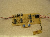
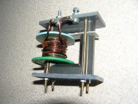
Here’s the promised pics
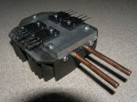
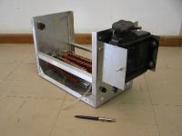
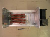
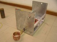
 )
)Raka, Sat Dec 06 2008, 02:12PM
Here’s the promised pics


Re: Induction heater (featuring my new PLL driver  )
)
uzzors2k, Sat Dec 06 2008, 02:53PM
Nice. Do you have heating problems with your matching inductor? The wire looks a little charred.
 )
)uzzors2k, Sat Dec 06 2008, 02:53PM
Nice. Do you have heating problems with your matching inductor? The wire looks a little charred.
Re: Induction heater (featuring my new PLL driver  )
)
Myke, Sat Dec 06 2008, 10:52PM
Looks like you used solid wire for the matching inductor. You probably want to use litz wire seeing that it's good for high frequency use.
 )
)Myke, Sat Dec 06 2008, 10:52PM
Looks like you used solid wire for the matching inductor. You probably want to use litz wire seeing that it's good for high frequency use.
Re: Induction heater (featuring my new PLL driver  )
)
Steve Conner, Sun Dec 07 2008, 11:45AM
The mini radiator is a nice touch
If you're going to talk about your induction heater more, you should think of starting another thread instead of jacking Uzzors' project thread.
Also, you probably ought to get a scope. Troubleshooting stuff like this without one is like doing a jigsaw puzzle with your eyes shut. And asking for help is like asking us to talk you through doing a jigsaw puzzle with your eyes shut, over the phone. For free. So at least meet us halfway, get a scope and learn what the green squiggles mean.
 )
)Steve Conner, Sun Dec 07 2008, 11:45AM
The mini radiator is a nice touch

If you're going to talk about your induction heater more, you should think of starting another thread instead of jacking Uzzors' project thread.
Also, you probably ought to get a scope. Troubleshooting stuff like this without one is like doing a jigsaw puzzle with your eyes shut. And asking for help is like asking us to talk you through doing a jigsaw puzzle with your eyes shut, over the phone. For free. So at least meet us halfway, get a scope and learn what the green squiggles mean.
Re: Induction heater (featuring my new PLL driver  )
)
Proud Mary, Sun Dec 07 2008, 01:33PM
All wonderful, Uzzors!
Is there some sort of relationship between input power and the temperature of the work?
Does efficiency fall as the work gets hotter, and its resistance rises?
Does the Curie temperature have any effect when the work is ferromagentic ?
I know nothing about it, but it certainly looks very interesting indeed.
 )
)Proud Mary, Sun Dec 07 2008, 01:33PM
All wonderful, Uzzors!
Is there some sort of relationship between input power and the temperature of the work?
Does efficiency fall as the work gets hotter, and its resistance rises?
Does the Curie temperature have any effect when the work is ferromagentic ?
I know nothing about it, but it certainly looks very interesting indeed.
Re: Induction heater (featuring my new PLL driver  )
)
Raka, Sun Dec 07 2008, 07:29PM
Sorry Uzzors, I didnt meen to take over your thread with my stuff. Im not so familiar with the etics. I did get the circuit to work in the meantime and it was largely due to your help. Big thanks!
Steve. Please delete my posts.
 )
)Raka, Sun Dec 07 2008, 07:29PM
Sorry Uzzors, I didnt meen to take over your thread with my stuff. Im not so familiar with the etics. I did get the circuit to work in the meantime and it was largely due to your help. Big thanks!
Steve. Please delete my posts.
Re: Induction heater (featuring my new PLL driver  )
)
uzzors2k, Mon Dec 08 2008, 11:10PM
Hi Harry, if we make the assumption that the work peice is a black body, then it will radiate more energy as the temperature increases, as well as receive energy from the surroundings, like anything else. It will also receive energy from the IH, which increases the temperature above ambient. So the maximum temperature of the work piece will occur when the radiated input and output power are in equilibrium. Now actually setting up an equation for this shouldn't be too hard, as it only requires Stefan–Boltzmann law and some assumptions or constants. I've made a crude equation, and the resulting temperatures aren't far off what I would expect. The hard part is determining such things as how "black" the work peice actually is, and how much power is actually being coupled into the work piece at any given time. Also, the curie temperature comes into effect, reducing the magnetic losses in the work peice, effectively coupling less power into it.
The effect the IH has on the work is somewhat complicated and I can't say I understand all the physics behind it yet. But I've observed that the work peice will load the tank circuit more as it heats up. This continues until the Curie temperature is reached (the exact time can actually be seen on a scope because the tank voltage rises quickly), then the work loads the tank less. The power throughput to the work peice is reduced when the tank is loaded, and increases as it becomes unloaded. This has to do with tank Q and circulating current in the work coil. Hopefully this gives you something to go on! As always, I'll point you to Richie's IH page, which has the physics as well as electronics explained.
Raka, don't worry about. I like having user-projects in the thread. Makes it look popular.
 )
)uzzors2k, Mon Dec 08 2008, 11:10PM
Hi Harry, if we make the assumption that the work peice is a black body, then it will radiate more energy as the temperature increases, as well as receive energy from the surroundings, like anything else. It will also receive energy from the IH, which increases the temperature above ambient. So the maximum temperature of the work piece will occur when the radiated input and output power are in equilibrium. Now actually setting up an equation for this shouldn't be too hard, as it only requires Stefan–Boltzmann law and some assumptions or constants. I've made a crude equation, and the resulting temperatures aren't far off what I would expect. The hard part is determining such things as how "black" the work peice actually is, and how much power is actually being coupled into the work piece at any given time. Also, the curie temperature comes into effect, reducing the magnetic losses in the work peice, effectively coupling less power into it.
The effect the IH has on the work is somewhat complicated and I can't say I understand all the physics behind it yet. But I've observed that the work peice will load the tank circuit more as it heats up. This continues until the Curie temperature is reached (the exact time can actually be seen on a scope because the tank voltage rises quickly), then the work loads the tank less. The power throughput to the work peice is reduced when the tank is loaded, and increases as it becomes unloaded. This has to do with tank Q and circulating current in the work coil. Hopefully this gives you something to go on! As always, I'll point you to Richie's IH page, which has the physics as well as electronics explained.

Raka, don't worry about. I like having user-projects in the thread. Makes it look popular.

Re: Induction heater (featuring my new PLL driver  )
)
Proud Mary, Mon Dec 08 2008, 11:56PM
Thanks very much, Uzzors - there's a lot to think about there - and exciting too!
 )
)Proud Mary, Mon Dec 08 2008, 11:56PM
Thanks very much, Uzzors - there's a lot to think about there - and exciting too!

Re: Induction heater (featuring my new PLL driver  )
)
Raka, Tue Dec 09 2008, 06:01PM
It seems the diode across the resistor of your soft start is rather critical. I didn’t have the RPG10A, so I used another of the 1N4148’s and that caused the soft start to hold the frequency above resonance. Do you have an explanation as to why you used a fast diode there, it looks as if right about any diode will do the job there, but obviously not. Mine is working fine without a diode until I get can get the proper one.
 )
)Raka, Tue Dec 09 2008, 06:01PM
It seems the diode across the resistor of your soft start is rather critical. I didn’t have the RPG10A, so I used another of the 1N4148’s and that caused the soft start to hold the frequency above resonance. Do you have an explanation as to why you used a fast diode there, it looks as if right about any diode will do the job there, but obviously not. Mine is working fine without a diode until I get can get the proper one.
Re: Induction heater (featuring my new PLL driver  )
)
uzzors2k, Tue Dec 09 2008, 07:14PM
The diode is there to allow for quick turn-on/off sessions. If you turn the inverter on and off, then quickly on again the soft-start wouldn't work without, unless the diode is in place. Those little 1N4148's are faster than the diode I have there, but their current handling ability isn't good enough.
 )
)uzzors2k, Tue Dec 09 2008, 07:14PM
The diode is there to allow for quick turn-on/off sessions. If you turn the inverter on and off, then quickly on again the soft-start wouldn't work without, unless the diode is in place. Those little 1N4148's are faster than the diode I have there, but their current handling ability isn't good enough.
Re: Induction heater (featuring my new PLL driver  )
)
Raka, Sun Dec 14 2008, 10:16AM
Somewhere Im still missing something. You mention that you can draw up to 18A from your inverter, you supply rail is 320V. That’s a lot more Watts than can be supplied by 4 IRFP460’s. Did you lower your supply rail with a variac?
 )
)Raka, Sun Dec 14 2008, 10:16AM
Somewhere Im still missing something. You mention that you can draw up to 18A from your inverter, you supply rail is 320V. That’s a lot more Watts than can be supplied by 4 IRFP460’s. Did you lower your supply rail with a variac?
Re: Induction heater (featuring my new PLL driver  )
)
MRacerxdl, Sun Dec 14 2008, 02:43PM
No, its not. 18A for the IRFP460 is only 87W. (It have Rds(on) about 0.27R)
If you get ohm law: P = R * I²
P = 0.27 * 18² => 324 * 0,27 = 87W
Considering that IRFP460 can dissipate about 300W, that is far from the more that it can support.
 )
)MRacerxdl, Sun Dec 14 2008, 02:43PM
No, its not. 18A for the IRFP460 is only 87W. (It have Rds(on) about 0.27R)
If you get ohm law: P = R * I²
P = 0.27 * 18² => 324 * 0,27 = 87W
Considering that IRFP460 can dissipate about 300W, that is far from the more that it can support.
Re: Induction heater (featuring my new PLL driver  )
)
uzzors2k, Sun Dec 14 2008, 05:28PM
Actually I used IRFP450s, each doubled up. SO, 18A peak or 13A RMS shared (hopefully) between two mosfets with an rds of 0,44R. That's about 20W of power dissipation per device, but since they only conduct for half the time we'll say 15W. (Switching losses play in as well.) Giving 60W of power lost in the fets. It's important to note that:
1) This is power LOST in the MOSFETs, the only way it affects output power is whether it approaches the maximum of what the IRFP450s can handle.
2) The 18A circulate in the tank/inverter loop and is largely reactive current, the actual current drawn from mains is probably 3-5A.
 )
)uzzors2k, Sun Dec 14 2008, 05:28PM
Actually I used IRFP450s, each doubled up. SO, 18A peak or 13A RMS shared (hopefully) between two mosfets with an rds of 0,44R. That's about 20W of power dissipation per device, but since they only conduct for half the time we'll say 15W. (Switching losses play in as well.) Giving 60W of power lost in the fets. It's important to note that:
1) This is power LOST in the MOSFETs, the only way it affects output power is whether it approaches the maximum of what the IRFP450s can handle.
2) The 18A circulate in the tank/inverter loop and is largely reactive current, the actual current drawn from mains is probably 3-5A.
Re: Induction heater (featuring my new PLL driver  )
)
Experimentonomen, Sun Dec 14 2008, 05:47PM
paralelling fets meand half the rdson, not twice as you imply.
 )
)Experimentonomen, Sun Dec 14 2008, 05:47PM
paralelling fets meand half the rdson, not twice as you imply.
Re: Induction heater (featuring my new PLL driver  )
)
Raka, Sun Dec 14 2008, 09:36PM
I obviously have a huge gap in my understanding of the FET specs. If I look at the save operating area graph of the IRFP460, at 300V (drain to source) a dc value of about 0.7A can be drawn continuously? Thus for a 50% duty cycle it must be about 1.7A per FET. Can someone please refer my to a webpage that can help to explain.
 )
)Raka, Sun Dec 14 2008, 09:36PM
I obviously have a huge gap in my understanding of the FET specs. If I look at the save operating area graph of the IRFP460, at 300V (drain to source) a dc value of about 0.7A can be drawn continuously? Thus for a 50% duty cycle it must be about 1.7A per FET. Can someone please refer my to a webpage that can help to explain.
Re: Induction heater (featuring my new PLL driver  )
)
Steve Conner, Sun Dec 14 2008, 10:05PM
The beauty of switched-mode power is that the FET is either off or on. (Anything in between - part on or part off - is not switched mode, but linear operation, which went out of fashion in the 1970s.)
When it's off, it has a high voltage across it, but no current flowing, therefore the power dissipated is zero. (Power is voltage times current, and anything multiplied by zero is zero.)
When it's on, it has a high current flowing, but no voltage across it. (We assume Rds(on) is so small that the IR drop is negligible.) So the power dissipated is again zero.
So this means a switched-mode circuit can pass infinite power without getting hot
Well not exactly, but it means that it can handle far more than what you said, because the 300V and 1.7A are never present at the same time. I would expect a fullbridge of IRFP460s to deliver a couple of kilowatts at hobbyist levels of reliability, while dissipating roughly the 50W or so of heat that Uzzors suggested.
 )
)Steve Conner, Sun Dec 14 2008, 10:05PM
The beauty of switched-mode power is that the FET is either off or on. (Anything in between - part on or part off - is not switched mode, but linear operation, which went out of fashion in the 1970s.)
When it's off, it has a high voltage across it, but no current flowing, therefore the power dissipated is zero. (Power is voltage times current, and anything multiplied by zero is zero.)
When it's on, it has a high current flowing, but no voltage across it. (We assume Rds(on) is so small that the IR drop is negligible.) So the power dissipated is again zero.
So this means a switched-mode circuit can pass infinite power without getting hot

Well not exactly, but it means that it can handle far more than what you said, because the 300V and 1.7A are never present at the same time. I would expect a fullbridge of IRFP460s to deliver a couple of kilowatts at hobbyist levels of reliability, while dissipating roughly the 50W or so of heat that Uzzors suggested.
Re: Induction heater (featuring my new PLL driver  )
)
uzzors2k, Sun Dec 14 2008, 10:11PM
For the love of god, my inverter uses IRFP4 -> 50 <- mosfets. Not IRFP460, so everyone stop bringing them up.
Now Raka, the maximum drain current specified in mosfet datasheets is DC current. Currents beyond this heat the junction (inside the mosfet package) faster than heat can be removed from the package. This has to do with thermal resistance. For all practical use the junction temperature is what limits the mosfet's current rating. You seem to have Ohm's law down, but not generel circuit analysis.
The following example applies to a single IRFP450, and isn't related to the inverter. It's just food for thought.
When mosfets are used in switching applications like this, they can be thought of as switches with some resistance, in this case 0,4 ohms. Now apply Ohm's Law to the switch. 0,4R * 14A = 5,6V So the voltage across the mosfet is only 5,6V when it's on and actually passing current. That means the dissipation in the conducting mosfet has to be 78W. The rest of the 300 - 5,6 = 294,4V are across the load, which I'll call LOAD. The power dissipated in LOAD is 294,4V * 14A = 4kW. When the mosfet is off the resistance is astronomic, and the full 300V will be across it. However, since no current flows through the mosfet the power dissipated in it has to be 0W. Is it any clearer?
Edit: Steve beat me to it.
 )
)uzzors2k, Sun Dec 14 2008, 10:11PM
For the love of god, my inverter uses IRFP4 -> 50 <- mosfets. Not IRFP460, so everyone stop bringing them up.
Now Raka, the maximum drain current specified in mosfet datasheets is DC current. Currents beyond this heat the junction (inside the mosfet package) faster than heat can be removed from the package. This has to do with thermal resistance. For all practical use the junction temperature is what limits the mosfet's current rating. You seem to have Ohm's law down, but not generel circuit analysis.
The following example applies to a single IRFP450, and isn't related to the inverter. It's just food for thought.
When mosfets are used in switching applications like this, they can be thought of as switches with some resistance, in this case 0,4 ohms. Now apply Ohm's Law to the switch. 0,4R * 14A = 5,6V So the voltage across the mosfet is only 5,6V when it's on and actually passing current. That means the dissipation in the conducting mosfet has to be 78W. The rest of the 300 - 5,6 = 294,4V are across the load, which I'll call LOAD. The power dissipated in LOAD is 294,4V * 14A = 4kW. When the mosfet is off the resistance is astronomic, and the full 300V will be across it. However, since no current flows through the mosfet the power dissipated in it has to be 0W. Is it any clearer?

Edit: Steve beat me to it.

Re: Induction heater (featuring my new PLL driver  )
)
Raka, Mon Dec 15 2008, 03:08PM
Its clear now, thanks.
 )
)Raka, Mon Dec 15 2008, 03:08PM
Its clear now, thanks.
Re: Induction heater (featuring my new PLL driver  )
)
Raka, Thu Dec 18 2008, 12:18PM
Ok, another question: In a setup like yours, with FET’s in paralleled. What is the pros and cons of a winding for each FET on the gate drive transformer or just one winding for the high side and one winding for the low side, driving more than one FET with a winding?
 )
)Raka, Thu Dec 18 2008, 12:18PM
Ok, another question: In a setup like yours, with FET’s in paralleled. What is the pros and cons of a winding for each FET on the gate drive transformer or just one winding for the high side and one winding for the low side, driving more than one FET with a winding?
Re: Induction heater (featuring my new PLL driver  )
)
uzzors2k, Thu Dec 18 2008, 12:54PM
The simplest approach is to simply parallel the mosfets and then consider them a single larger mosfet. The gate capacitance will be larger, the current handling roughly the same, but the power dissipation will be halved. I found that the gate driver had no problem driving twice the capacitance fast enough. Unless the switching waveforms become unreasonably sloped, there is little point in using a second GDT with separate gate drivers to power the other set of mosfets. If you're thinking of using four secondary windings and putting pairs in parallel, that will only reduce the resistance of the secondary, which is often negligible to start with.
 )
)uzzors2k, Thu Dec 18 2008, 12:54PM
The simplest approach is to simply parallel the mosfets and then consider them a single larger mosfet. The gate capacitance will be larger, the current handling roughly the same, but the power dissipation will be halved. I found that the gate driver had no problem driving twice the capacitance fast enough. Unless the switching waveforms become unreasonably sloped, there is little point in using a second GDT with separate gate drivers to power the other set of mosfets. If you're thinking of using four secondary windings and putting pairs in parallel, that will only reduce the resistance of the secondary, which is often negligible to start with.
Re: Induction heater (featuring my new PLL driver  )
)
Raka, Sat Dec 20 2008, 05:55PM
I know you don’t like the mention of the name But what made you decide on the irfp 450? It seems to me as if the irfp 460 is a superior IC
 )
)Raka, Sat Dec 20 2008, 05:55PM
I know you don’t like the mention of the name
 But what made you decide on the irfp 450? It seems to me as if the irfp 460 is a superior IC
Re: Induction heater (featuring my new PLL driver  )
)
Experimentonomen, Sat Dec 20 2008, 07:06PM
I´d suggest igbt below 100KHz.
 )
)Experimentonomen, Sat Dec 20 2008, 07:06PM
I´d suggest igbt below 100KHz.
Re: Induction heater (featuring my new PLL driver  )
)
uzzors2k, Sat Dec 20 2008, 11:07PM
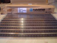
Hehe, they are better of course. Well, a trade off really, the gate capacitance is much larger IIRC. Either way it doesn't matter, I'm on a student's budget, and I have had these at my disposal for a long time now. I'm maybe half-way through the pile, haven't checked for some time.
 )
)uzzors2k, Sat Dec 20 2008, 11:07PM
Hehe, they are better of course. Well, a trade off really, the gate capacitance is much larger IIRC. Either way it doesn't matter, I'm on a student's budget, and I have had these at my disposal for a long time now. I'm maybe half-way through the pile, haven't checked for some time.

Re: Induction heater (featuring my new PLL driver  )
)
Raka, Thu Jan 08 2009, 06:49PM
That’s a lot of reasons toe use IRFP 450s
There’s something which isn’t so obvious at first glance, that Ive learned the hard way. If you use a fixed length of copper tubing for the work coil, it doesn’t matter if you wind a lot of small diameter windings or if you wind only a couple of big diameter windings. The induction of the coil stays the same. I confirmed this in my physics book as well.
Mabye it saves someone some trouble when building this induction heater
 )
)Raka, Thu Jan 08 2009, 06:49PM
That’s a lot of reasons toe use IRFP 450s

There’s something which isn’t so obvious at first glance, that Ive learned the hard way. If you use a fixed length of copper tubing for the work coil, it doesn’t matter if you wind a lot of small diameter windings or if you wind only a couple of big diameter windings. The induction of the coil stays the same. I confirmed this in my physics book as well.
Mabye it saves someone some trouble when building this induction heater
Re: Induction heater (featuring my new PLL driver  )
)
Dr. Dark Current, Thu Jan 08 2009, 09:43PM
Uzzors, you can parallel MOSFETs for higher powers.
 )
)Dr. Dark Current, Thu Jan 08 2009, 09:43PM
Raka wrote ...
There’s something which isn’t so obvious at first glance, that Ive learned the hard way. If you use a fixed length of copper tubing for the work coil, it doesn’t matter if you wind a lot of small diameter windings or if you wind only a couple of big diameter windings. The induction of the coil stays the same. I confirmed this in my physics book as well.
Well, you should make the coil just bigger than your intended work piece to ensure the best coupling.There’s something which isn’t so obvious at first glance, that Ive learned the hard way. If you use a fixed length of copper tubing for the work coil, it doesn’t matter if you wind a lot of small diameter windings or if you wind only a couple of big diameter windings. The induction of the coil stays the same. I confirmed this in my physics book as well.
Uzzors, you can parallel MOSFETs for higher powers.
Print this page