
4.5MHz Tesla coil simulation and testing
WaveRider, Mon Mar 13 2006, 11:59AMGiven the first encouraging tests with my 4.5MHz MOSFET-based Tesla coil, I can't resist the urge to attempt a high power HF tesla coil. I have successfully modeled some Class-E amps (for my own understanding of their operation)...so, the plan at this point is:
1. I want to try to get true high-power Class-E operation at 4.5 MHz with 2SK2698s.
2. Determine if the Royer topology is suitable or should changes be made to optimise the turn-on/turn off times to minimise power dissipation in the transistors.
3. Model the resonator (with all the required coupling). The coupled resonator is not so trivial, because all the coupling parameters are not accurately known (by me, at least). This makes the Spice modeling of the Royer topology difficult. Will try a full field model of the resonator.
4. Once I am satisfied with the results...on to higher frequencies!!!
Keep an eye on my new Tesla coil page. I will post updates here as well!
EDIT 20060314:
As part of objective 1: Just posted some initial simulation studies of class-E operation here..

Have a look. Be aware that it is a work in progress... (lot's more simulation and experimental studies to do!)
Cheers!
EDIT20060323:
Got some new modeling results on the resonator. The use of push-pull primary windings is not as simple as it seems. This is because the primary-secondary coupling varies strongly with position as well as with the inter-primary coupling. I present some S-parameter data for a simple two-primary excited resonator. I basically ignore the gate-drive loops in the initial study, because it would complicate things too much. Plus, it is possible to use capacitive coupling from the primaries (drain circuit) to get Royer-like behaviour (SPICE sims confirm this).
I want to use the S-Parameter data from the field simulation to guide the development of a lumped circuit model for the resonator (including all the coupling).
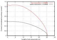
In the meantime, here are some selected results from the field sims. This is the current along the helix. Notice how it is not constant, as you would expect for a normal lumped inductor. Instead, it takes on a (not quite) sinusoidal shape.
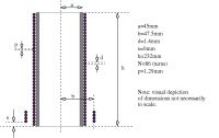
The following is a section showing the pertinent dimensions used to generate the results of my study so far....
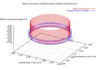
Here is the NEC generated discretisation of the secondary and primary windings near the base of the coil.
Go to
 if you want to see more results.
The conclusion at this point is that true Class-E operation for the Royer-like oscillator will likely be difficult with a simple circuit. With careful primary construction and proper matching of drain and gate dircuits, it may be possible....then it may be simpler to use a single-sided Class-E amplifier to get the same result...
EDIT 20060329: Just received my first shipment of bits for a '4.5MHz Class-E driver for the next generation of the coil... Stay tuned!!

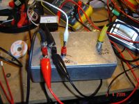
EDIT 20060403: Got the first version of my Class E amplifier to work. Here's a pic of the completed amp in an RF-tight die-cast box. Input and outputs are terminated in 50 ohms. This amp does not like mismatches.. Try to keep the SWR lower than 1.2-1.3. Otherwise, it will overheat. Low impedance loads or short circuits on the output will immediately kill the power transistor (bitter experience speaks on this one!
 )
) 
So far, I have tested the amp using relatively low power (VDD = 30V). While this amp should happily generate 300-400 watts with a 100V supply (theoretically speaking), it easily generates 100W from my 30V bench-top supply.
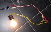
The 100watt globe (which has about 240 ohm resistance) is reasonably matched to the 50 ohm output using a ferrite cored transformer that supplies a 4:1 impedance ratio for low SWR (in fact, SWR < 1.2)
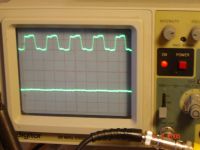
The gate drive looks like this:
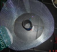
Here's a pic of the modified tesla coil resonator. I pruned the secondary (removed 8 windings) to raise the resonant frequency to around 4.7MHz..
These pics show the feed:
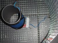
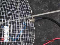
With four windings on the primary, the input impedance at resonance is a bit low, so I used my 4:1 transformer from the light-globe experiment to reduce the 50 ohm output from the amplifier to a bit more than 12 ohms to feed the tesla coil primary. A 1000 pF cap is in series with the 50 ohm side of the transformer. It's not perfect, but it yielded an almost acceptable 1.3 SWR during tesla coil operation.
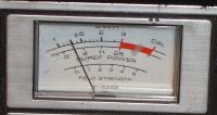
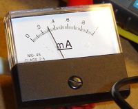
The amplifier current draw from the 30 volt VDD supply is slightly less than 3 amperes.
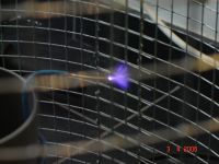
Here's the spark!
EDIT 20060405:
Or a short movie:

The drain current draw was about 3 amps at 30 volts (90 watts into the amplifier drain circuit). The SWR was measured at 1.3 (98% of power absorbed by load). Some losses are incurred by the ferrite core of the matching transformer (several percent...not extremely efficient), so spark power was probably on the ball-park of 60 watts.. I am waiting on some high-efficiency toroids for high-power matching networks before I try to fire up the coil with the 100V supply. Otherwise, I will just sacrifice my power MOSFETs.
EDIT 20060404: Given that the primary input has an impedance (with spark at resonance) of 10-12 ohms, direct drive from the drain circuit should yield good results, with proper choice of drain capacitor, choke and DC source. (Back to a bit of modeling).
Some results of experiments:
Simulations of the ideal resonator indicate a complicated resonance phenomenon. First, a high-impedance "parallel-like" resonance just under 4.76MHz followed by a low-impedance "series-like" resonance about 80kHz higher. The low-impedance resonance, as far as I can see, gives the big sparks...since stepping the impedance in the experimental trials down gives the best spark results.
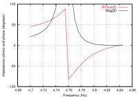
I need to build a circuit model of this for SPICE simulations in order to verify that the series resonance is indeed the important one..
***NOTE: Spice model of a weakly coupled LC circuit yields the same frequency response as the TC secondary (as we'd expect, although the weak coupling was a bit of a suprise..) The closer the "series" and "parallel" resonances, the weaker the coupling. On to modeling the complete oscillator!
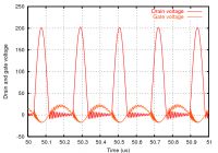
EDIT 20060407: Spice model of oscillator with 2SK2698 yields the following waveform. Coupling between primary and secondary was computed from the NEC model to yield a circuit model of the resonator.
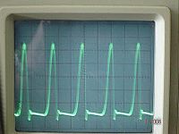
This is the measured waveform on the drain of the driving transistor. Looks somewhere between Class C and E....
Go to
 for more details and photos.
EDIT 20060620:
Got to spend a few hours tinkering with my HFTC. I replaced the four original primary windings with ten. With the old primary, the simulations and measurements indicated a real component of impedance of around 8-10 ohms (depends heavily on the arc size). I want something near 50 ohms at resonance, with a good arc.. Classical transformer calculation indicates a need to increase the windings by 2.2-2.5 (from 4 turns to 9 turns). Given that the primary does not experience perfect coupling with the secondary, an extra turn probably couldn't hurt...
It turns out that with my Class-E amplifier supplying 100 watts, this modified primary exhibits a nearly perfect 50 impedance. (Of course, there are fluctuations because of varying arc loading). When the arc appears, the resonant frequency decreases by about 30kHz. The amplifier happily pumps 100W CW into the coil (it's been running for two hours at the time of this posting with no sign of overheating...) Woot!!
When I get around to it, three things are in the works at this stage:
1. PLL tracking oscillator (much like Steve Ward's)
2. Audio modulation
3. More power babee! More power!!!
The amplifier method seems to offer possibilities for scaling (using power combiners). Hence, large powers can be had by using lots of cheap silicon instead of single expensive high-power devices.
Re: 4.5MHz Tesla coil simulation and testing
WaveRider, Mon Apr 03 2006, 02:42PM
Updated this thread with Class-E amplifier trial..
Cheers!
WaveRider, Mon Apr 03 2006, 02:42PM
Updated this thread with Class-E amplifier trial..
Cheers!
Re: 4.5MHz Tesla coil simulation and testing
Marko, Mon Apr 03 2006, 06:00PM
Hi,
As I can figure out from you are feeding TC primary with 50 ohm otuput of a RF amplifier
Maybe I misunderstood, and I dont want to badger, but with class E SSTCs primary is usually used as inductor and a capacitor is placed across mosfet.
They are tuned and mosfet is fed with signal from gate driver.
So primary, tank cap and mosfet are together one class E amplifier.
Steve Ward's class E coil uses only more one UCC driver with antenna as gatedriver and results are very nice:

Oscilaltor can also be used but then there are more things to tune, and I think your coil can do a lot better.
EDIT: Could you try to reconfigure your amp (when using independent choke) without output filter stage, just with DC blocking cap? You are obivously smarter than me in that field, and you'l probably suit yourself.
cheers...
Marko, Mon Apr 03 2006, 06:00PM
Hi,
As I can figure out from you are feeding TC primary with 50 ohm otuput of a RF amplifier

Maybe I misunderstood, and I dont want to badger, but with class E SSTCs primary is usually used as inductor and a capacitor is placed across mosfet.
They are tuned and mosfet is fed with signal from gate driver.
So primary, tank cap and mosfet are together one class E amplifier.
Steve Ward's class E coil uses only more one UCC driver with antenna as gatedriver and results are very nice:

Oscilaltor can also be used but then there are more things to tune, and I think your coil can do a lot better.
EDIT: Could you try to reconfigure your amp (when using independent choke) without output filter stage, just with DC blocking cap? You are obivously smarter than me in that field, and you'l probably suit yourself.
cheers...
Re: 4.5MHz Tesla coil simulation and testing
ragnar, Tue Apr 04 2006, 07:22AM
Very impressive, Doctor. =)
Believe it or not I was just about to fire up my scope and work out matching networks. I'll let you know how it goes. The target is ~6.45MHz, but I think I'll have to start at a quarter of that (or wind a new resonator.. aww) as I don't have any oscillators that go up that high yet (still waiting for my MAX038s).
Stay in touch!
Re: 4.5MHz Tesla coil simulation and testing
WaveRider, Tue Apr 04 2006, 09:38AM
Yes, I am. I know it seems strange, but my goal at this stage is not to produce big sparks, but to understand the impedance changes with respect to frequency and power level. Using an amplifier based on a standard 50 ohm impedance makes this convenient. I also wanted to judge the suitability of the 2SK2698 for my experiments. (See update to original post). On top of that, now I have a nice amplifier capable of 200W or so for other experiments later! Think of it as 2 projects for the price of 1.
I have read through Steve Ward's stuff and it is indeed impressive. (I will try to replicate his fine sparks when I reconstruct the power oscillator..probably a self-starting Armstrong topology...somewhat different from Steve's.) My goal is to understand the ideal drain-circuit impedance relationships in more detail than that given by previous work.... Also, modeling the coupled resonant circuit is not so straightforward. Trial-and-error seems to be the most used technique.
Good call Firkragg. This is precisely the topology I had in mind for the coupling to the primary. The filter/matching stage will not be there in the oscillator. The primary impedance with a spark seems to be around 12 ohms (mostly resistive with some inductive component, indicated in simulations as well as my recent measurements). I plan to return to some simulations now that I know more about the resonator characteristics to establish the component values. Don't want to smoke too many precious MOSFETs!
Thanks BP. I am using IXDD414 drivers...They run relatively cool at 4.5-5MHz. They are limited to about 10MHz. My experiments indicate that at 10MHz, they run fairly hot driving the gate of the 2sk2698, but if a good heat-sink is used, it is possible.
WaveRider, Tue Apr 04 2006, 09:38AM
As I can figure out from you are feeding TC primary with 50 ohm otuput of a RF amplifier
Yes, I am. I know it seems strange, but my goal at this stage is not to produce big sparks, but to understand the impedance changes with respect to frequency and power level. Using an amplifier based on a standard 50 ohm impedance makes this convenient. I also wanted to judge the suitability of the 2SK2698 for my experiments. (See update to original post). On top of that, now I have a nice amplifier capable of 200W or so for other experiments later! Think of it as 2 projects for the price of 1.

Steve Ward's class E coil uses only more one UCC driver with antenna as gatedriver and results are very nice:
I have read through Steve Ward's stuff and it is indeed impressive. (I will try to replicate his fine sparks when I reconstruct the power oscillator..probably a self-starting Armstrong topology...somewhat different from Steve's.) My goal is to understand the ideal drain-circuit impedance relationships in more detail than that given by previous work.... Also, modeling the coupled resonant circuit is not so straightforward. Trial-and-error seems to be the most used technique.
Could you try to reconfigure your amp (when using independent choke) without output filter stage, just with DC blocking cap? You are obivously smarter than me in that field, and you'l probably suit yourself.
Good call Firkragg. This is precisely the topology I had in mind for the coupling to the primary. The filter/matching stage will not be there in the oscillator. The primary impedance with a spark seems to be around 12 ohms (mostly resistive with some inductive component, indicated in simulations as well as my recent measurements). I plan to return to some simulations now that I know more about the resonator characteristics to establish the component values. Don't want to smoke too many precious MOSFETs!

Very impressive, Doctor. =)
Thanks BP. I am using IXDD414 drivers...They run relatively cool at 4.5-5MHz. They are limited to about 10MHz. My experiments indicate that at 10MHz, they run fairly hot driving the gate of the 2sk2698, but if a good heat-sink is used, it is possible.
Re: 4.5MHz Tesla coil simulation and testing
WaveRider, Fri Apr 07 2006, 09:07AM
Posted an update to project. Reliable Class-E operation with a very simple Armstrong-like oscillator...
WaveRider, Fri Apr 07 2006, 09:07AM
Posted an update to project. Reliable Class-E operation with a very simple Armstrong-like oscillator...
Re: 4.5MHz Tesla coil simulation and testing
Steve Conner, Fri Apr 07 2006, 09:18AM
WaveRider: All untuned primary SSTCs have that behaviour. Since the equivalent circuit contains two inductors and one capacitor, they are sort of third-order networks. The series resonance is the important one. The parallel resonance gives more or less zero output voltage. Excellent work btw!
Re: 4.5MHz Tesla coil simulation and testing
WaveRider, Fri Apr 07 2006, 09:34AM
Hi Steve,
Yeah.. I sorta figured that one out. For inductively coupled resonant circuits, you get the "parallel" resonance first and the "series" one second. Vice-versa for capacitively coupled ones. I should have remembered this from the days when I built duplexing filters...
Which resonance is important depends on the type of driving circuit. If the driver looks like a current-source, the parallel resonance will be excited. If it looks like a voltage source (like the fully on or off MOSFET will look like), the series resonance is important.
Also...thanks for the kudos!
Re: 4.5MHz Tesla coil simulation and testing
WaveRider, Tue Jun 20 2006, 11:50AM
Added a note at the end of my first post about impedance matching between coil and power amplifier...
Cheers!!
WaveRider, Tue Jun 20 2006, 11:50AM
Added a note at the end of my first post about impedance matching between coil and power amplifier...
Cheers!!
Print this page