
A Short Loaded Dipole for 20m
Chris Russell, Fri Dec 21 2007, 11:15PMGreetings,
As some of you may know, I've been trying to get on the air lately, but I have an extremely limited amount of space in which to do so. I live in a bottom-floor aparment, and the building sits on an extremely small lot: roughly 60 feet by 110 feet (18m by 34m). My first antenna was a magnetic loop, which peformed quite well, but is rather large, heavy, and needs to be tuned constantly.
So, I decided to put together a loaded dipole. A dipole would have the advantage of being fairly broadband, while doing a good job of radiating. The dipole can be shortened by using a loading coil. Greater efficiency is possible by using a loading coil near the center of each leg, but this complicates the feedpoint of the antenna somewhat. I decided that a center-loaded dipole would be the best bet, as this would allow me to feed the antenna with a simple coupling loop. Additionally, a center-loaded dipole only needs one loading coil, which saves some time and effort. After running some figures through a simulator, I determined that a 16' (4.9m) long dipole could easily be more than 50% efficient on the 20m band, meaning it would perform less than 3dB (half an s-unit) down from a full-sized halfwave dipole.
Construction:
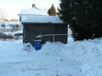
The dipole, from a distance. The PVC sections are 4' long, making the plastic section of the dipole a little more than 8' long. The pieces are not glued, for ease of assembly.
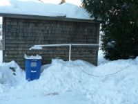
A closer look, showing the coax leading away.
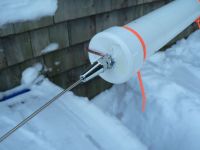
Each leg of the dipole is capped, and the cap is drilled out to accept a 3/8 bolt. I then attached the adjustable whip section. These were borrowed from a cheapo hamstick antenna, but similar hardware can be found elsewhere for cheap. The whips are 4' (1.2m) long. A stranded section of 14awg runs along the length of the PVC, secured by cable ties.
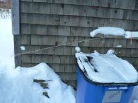
The ends droop a bit. It doesn't seem to hurt anything.
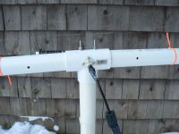
The center of the dipole is a PVC T-fitting, drilled out to accept a standard PL-259 socket. I also sealed the socket with silicone caulk, just in case moisture buildup became a problem. You can also see the coax here, and the clip-on ferrites that I use to prevent RF feedback issues. These are not really necessary, I just figured I would include them as a precautionary measure.
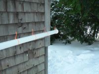
The other end of the antenna.
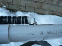
This is how I joined the loading coil to the 14AWG wire that runs to each end cap. Note that this is zinc-plated hardware, and the wires are copper. This joint needs to be waterproofed, or it will eventually corrode. Brass would be a better choice for this hardware.
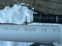
The other side.
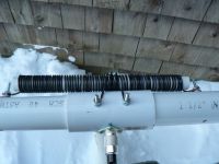
And, finally, the loading coil and coupling loop. The loading coil is 68 turns of 14AWG solid copper wire on a section of 1/2" PVC. Each end of the loading coil connects to each leg of the dipole. The coupling loop is 3 turns of the same wire, wound over the loading coil, spaced slightly wider. The coupling loop is simply connected to the coax.
Results:
The whips need careful adjustment to bring the antenna into resonance. Right now, the antenna is tuned to 14.040MHz, with an SWR of 1.5:1 or less from 14.000-14.120MHz. SWR is less than 2:1 to 14.170MHz. However, the antenna is rather close to the ground at this point, and the usable bandwidth may be approximately halved at an appreciable height above ground.
To test the performance of the antenna, I scheduled a QSO with Dave, AB3I, via PSK31. Over the nearly 2,000km path, results were very good, even down to power levels of 5 watts.
Re: A Short Loaded Dipole for 20m
ShawnLG, Sat Dec 22 2007, 08:09AM
That is nice work Chirs. You should install the antenna on top of that shed to give it some height.
ShawnLG, Sat Dec 22 2007, 08:09AM
That is nice work Chirs. You should install the antenna on top of that shed to give it some height.
Re: A Short Loaded Dipole for 20m
Chris Russell, Sat Dec 22 2007, 06:54PM
Yes, it does need some height. Unfortunately the shed is not mine, and is the subject of a dispute between the owner of this building and the neighbor. In the background of the first picture, you can see the base of my small homebrew tower. Eventually, I will dig that out, fix it up (a plow truck broke it a few weeks ago), and attach a 10 foot section of PVC, giving me about 13 feet of elevation. Not much, but it should improve performance considerably. Then, when the snow melts, I'll get another performance increase, as the 5' tall snow drifts will no longer be absorbing my RF.
Print this page