
Wireless powering SSTC
Marko, Fri Nov 16 2007, 11:59PMHi, all,
I've started this yet before summer, and actually done most of work over it, only to lose motivation to work on it after school started.
I'm going to post lots of pics, but I have too much questions I'd want to ask and so put this into TC board.
I would really want to make this thing work but I'm stuck... doing other projects just increased the already too big number of unfinished projects.
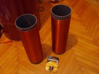
I had these larger 400kHz resonators sitting around unused. I thought it'd be cool if I could demonstratively power something wirelessly via capacitive coupling - and I decided to make that this coil's main use.
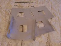
In order to pump larger amount of power, I needed beefier switches and heatsinking. I had no heatsinks even closely that big so I decided to construct one from aluminium sheet.
It was lot of work but looked good in the end...
I don't intend to filter or interrupt the coil yet. It'll simply run from mains, fullwave rectified.
I use 2 paralleled H bridges of IRFP450's. They were supposed to drive a bifilar primary.
I have really a ton of pics here and didn't know which to select - too many already.
They tell much more than words...
Aluminium I had cut up.
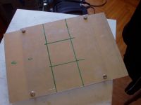
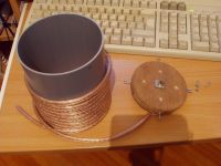
Resonators
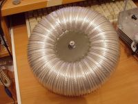
Toroid. I add a breakout point to that screw by need, or supress it by a ball to run at low power without breakout.
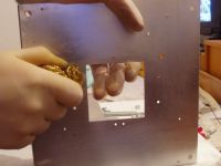
Cutting the hole inside the Al sheet was problematic - I managed to do it by screwing all sheets together and using drill and electric saw. Sheet and it's sawn edges looked crappy and I decided to give it a full polish with steel wool - boring work but made it look really cool in the end.
Bridge board layout. I stuck them deep inside but still didn't want to need to unsolder anything in orther to disassemble the thing. Probably owerwork though.
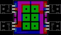
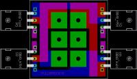
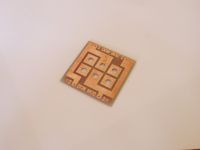
This is how I secure everything. Mosfets are oriented wierdly as you may notice, this is to give each mosfet his half of aluminium plane. THe fifth sheet has no mosfets on it, coold only the drivers and diode bridge.
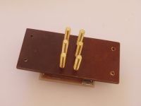
This is putting everything together. I weakly glued the sil pads and put grease over them - overkill too, but meh. Two plexy boards up and down make the ''case'' - the primary and secondary are held by a single brass bolt also serving as a ground contact. Spacers are put between two middle planes instead of mosfets. Nuts at the edges are drilled through and act only as 5mm spacers too.
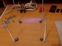
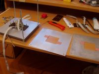
The primary form with the infamous speaker cable. :(
And secondary base holder with a brass nut soldered to a piece of PCB and secured. There goes secondary base.
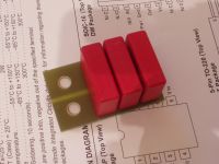
Decoupling caps:
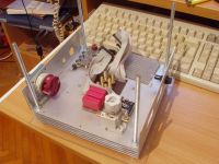
This is how the thing looks after assembly. I planned to build in a small SMPS for it, but I'll leave that for later. Connectors are to be built in.. power is separate for the bridge and controller section.
Now, questions:
- I intend to change the driver section by removing the 5V logic (Schmitt trigger) stage, use only 12V for drive. Drivers are UC 3710's. I wanted to use a center-tapped CT, clamped with zeners since that would give neat square wave alone; I have free inverted signal which I lead to input of non-inverting driver.
I start the thing up by discharging a small capacitor into the driver input via BS170 adn a diode, lasting few microseconds to initiate oscillation. Those would simply be done by flick of a switch, which also enables the dirvers - simply like a single-pulse startup circuit.
This gave a nice safety feature by making it impossible to turn the coil on by applying power to the bridge, and it looked elegant to me.
But now I wonder will this actually work? Other coils work smoothly at unfiltered fullwave rectified input... so secondary current isn't going to decay enough to stop the oscillation during that period, I hope?
Too bad I realize things like that only after I start building.
I should draw a full diagram now but it's too late and I can't think anymore...
- My primary now looks way too small to me. I looked at other coils using really low primary inductances like that and thought it should be OK... but I don't want to run interrupted only, and as it appears now I'll have 15A of magnetizing current!
I realized that after I actually bought the wire. This makes me too frustrated.
I'm going to post a lot more after I rest and get replies - I have too many pics here, and'll gladly take more, just ask for anything you want to see!

Marko
Re: Wireless powering SSTC
teslaguy, Sat Nov 17 2007, 04:14AM
marko, you are a god.
teslaguy, Sat Nov 17 2007, 04:14AM
marko, you are a god.
Re: Wireless powering SSTC
Zum Beispiel, Sat Nov 17 2007, 01:51PM
Looking good!
I see you have one of those big industrial switches there... I just love those! I've got one of them on my Beer Cooler (tm) and I just love the feeling of power it gives: Ka-Thunk! I remember being fascinated by them as a kid when I went to work with my dad. Ah, memories...
As for running unfiltered fullwave rectified: If it fails to oscillate, you can always use 555 to kick it back to oscillation. My halfwave SSTC won't oscillate without a 555 (secondary base feedback), but maybe with fullwave it won't be a problem.
Re: Wireless powering SSTC
Marko, Sat Nov 17 2007, 02:40PM
Thanks guys
I must not use 555 as it generally is because it will make the circuit unstable.
The ''proper'' way or startup would be a NE555 oscillator which would get immediately disabled by the driver as the oscillation starts.
The problem is that I haven't planned to build in something like that and won't have enough board space.... so 'll have to think something up if I end unable to oscillate.
One other thing, I saw lots of people reporting trouble with secondary base feedback. What's really up with it? I'm just drawing the diagram.
I wanted to reduce the complexity and delays to minimum but am very unsure if everything will work as I planned.
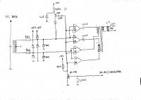
Now.. please, I need opinions on this! I use 4 of these drivers:
I just saw no purpose in 74HC14 and wanted to get rid of it.
After I push the button for turn-on I enable the drivers (active low input is pulled low) and PNP transstor is driven into conducting state. 5nF cap has been before charged to the supply voltage and is now suddenly dumped into the driver input. It's time constant with 5k resistor is 5us which is enough to get the oscillation going. After it's discharged insignifican current flows through 100k resistor.
I thought this would make neat safety feature because it makes impossible to turn the coil ON by any way except remote controller/modulator. (I don't plan using modulator yet).
If power to bridge is suddenly lost the button needs to be cycled to restart.
I use two paralelled drivers, each driving it's own primary on a single GDT to assure current sharing. 8 IRFP450's are driven in total.
Marko, Sat Nov 17 2007, 02:40PM
Thanks guys
I must not use 555 as it generally is because it will make the circuit unstable.
The ''proper'' way or startup would be a NE555 oscillator which would get immediately disabled by the driver as the oscillation starts.
The problem is that I haven't planned to build in something like that and won't have enough board space.... so 'll have to think something up if I end unable to oscillate.
One other thing, I saw lots of people reporting trouble with secondary base feedback. What's really up with it? I'm just drawing the diagram.
I wanted to reduce the complexity and delays to minimum but am very unsure if everything will work as I planned.

Now.. please, I need opinions on this! I use 4 of these drivers:

I just saw no purpose in 74HC14 and wanted to get rid of it.
After I push the button for turn-on I enable the drivers (active low input is pulled low) and PNP transstor is driven into conducting state. 5nF cap has been before charged to the supply voltage and is now suddenly dumped into the driver input. It's time constant with 5k resistor is 5us which is enough to get the oscillation going. After it's discharged insignifican current flows through 100k resistor.
I thought this would make neat safety feature because it makes impossible to turn the coil ON by any way except remote controller/modulator. (I don't plan using modulator yet).
If power to bridge is suddenly lost the button needs to be cycled to restart.
I use two paralelled drivers, each driving it's own primary on a single GDT to assure current sharing. 8 IRFP450's are driven in total.
Re: Wireless powering SSTC
Dr. Dark Current, Sat Nov 17 2007, 03:05PM
I find the base current feedback too much unreliable and unstable. Antenna feedback fixes this.
Dr. Dark Current, Sat Nov 17 2007, 03:05PM
Marko wrote ...
One other thing, I saw lots of people reporting trouble with secondary base feedback. What's really up with it? I'm just drawing the diagram.
The problem with secondary base feedback for SSTC arises when you try to draw any arcs to ground. Two things can happen- either it just stops oscillating or worse- your bridge explodes. I've been experimenting quite a lot with sec. CT feedback on my SSTC but I just could not get it right for ground arcs. One other thing, I saw lots of people reporting trouble with secondary base feedback. What's really up with it? I'm just drawing the diagram.
I find the base current feedback too much unreliable and unstable. Antenna feedback fixes this.
Re: Wireless powering SSTC
Marko, Sat Nov 17 2007, 03:28PM
Wasn't it told that ''antenna feedback is unreliable and unstable'', and that ''base current feedback fixes that''?
I used CT feedback with PLL and it worked fine... but I'm not too experienced with all these things.
Why would the bridge explode?
Marko, Sat Nov 17 2007, 03:28PM
I find the base current feedback too much unreliable and unstable. Antenna feedback fixes this.
Wasn't it told that ''antenna feedback is unreliable and unstable'', and that ''base current feedback fixes that''?
I used CT feedback with PLL and it worked fine... but I'm not too experienced with all these things.
Two things can happen- either it just stops oscillating or worse- your bridge explodes. I've been experimenting quite a lot with sec. CT feedback on my SSTC but I just could not get it right for ground arcs.
Why would the bridge explode?
Re: Wireless powering SSTC
Dr. Dark Current, Sat Nov 17 2007, 03:50PM


Dr. Dark Current, Sat Nov 17 2007, 03:50PM
wrote ...
Wasn't it told that ''antenna feedback is unreliable and unstable'', and that ''base current feedback fixes that''?
Maybe but I had exactly the opposite experience I find the base current feedback too much unreliable and unstable. Antenna feedback fixes this.
Wasn't it told that ''antenna feedback is unreliable and unstable'', and that ''base current feedback fixes that''?

wrote ...
Why would the bridge explode?
I don't know, mine did Why would the bridge explode?

Re: Wireless powering SSTC
Zum Beispiel, Sat Nov 17 2007, 06:12PM
I've been using base feedback for a while now with no failures...
With an antenna you have the problem that it can't be too close to the resonator. This is a problem when you want to box up the coil nicely. Sure, it may work, but seeing tiny arcs of corona shoot from an antenna, that is connected to a 5V chip, was too much for me
Getting the coil to oscillate with CT feedback was a fiddly process, but once I got it working, it continued to work (if you understand what I'm saying) Haven't tried pulling ground arcs, but from all I've seen secondary base feedback is the way to go.
Also, I'd like to add, that I've had no problems with using a 555 starter... I've set it up for ½ the operating frequency and the signal is greatly weakened before going into the feedback system. Zero problems. This is with around 300kHz operating frequency and the classic Steve W.-style feedback driver.
Just my 2cents
Zum Beispiel, Sat Nov 17 2007, 06:12PM
I've been using base feedback for a while now with no failures...
With an antenna you have the problem that it can't be too close to the resonator. This is a problem when you want to box up the coil nicely. Sure, it may work, but seeing tiny arcs of corona shoot from an antenna, that is connected to a 5V chip, was too much for me

Getting the coil to oscillate with CT feedback was a fiddly process, but once I got it working, it continued to work (if you understand what I'm saying) Haven't tried pulling ground arcs, but from all I've seen secondary base feedback is the way to go.
Also, I'd like to add, that I've had no problems with using a 555 starter... I've set it up for ½ the operating frequency and the signal is greatly weakened before going into the feedback system. Zero problems. This is with around 300kHz operating frequency and the classic Steve W.-style feedback driver.
Just my 2cents
Re: Wireless powering SSTC
Marko, Wed Nov 21 2007, 08:01PM
Well, all this I posted appears to be vain... interest in forum is just so low that no projects are worth posting anyway. Even much-more-famous guy's projects get ignored.
Marko, Wed Nov 21 2007, 08:01PM
Well, all this I posted appears to be vain... interest in forum is just so low that no projects are worth posting anyway. Even much-more-famous guy's projects get ignored.
Re: Wireless powering SSTC
Avalanche, Wed Nov 21 2007, 10:25PM
Well I find your project threads interesting to read, and I'm sure others do even though there aren't always a lot of replies. With a lot of things like this, I think it's just a case of 'try it and see', then report your findings. Your theory looks sound, and whether or not the coil will lose oscillation between cycles will depend on a number of characteristics of your setup. I'll add some of my thoughts, beware this might not be much use, and/or completely wrong, and that's the reason I don't usually write replies
You're using this for wireless power transfer, so I'm guessing you won't want to go creating streamers, therefore it does have a high chance of maintaining oscillation between cycles - due to the high q-factor which you should try to maintain as much as possible. I'm a bit worried that it will lose it with that CT on the secondary loaded with a 1k resistor but I could be wrong!
I actually tried a similar approach about a year and a half ago with a center tapped CT, but eventually I ended up doing something completely different : I used an ordinary CT, with a potential divider on it made with a couple of resistors. I grounded the center point, and this resulted in 2 sine waves 180 out of phase. The whole idea was to not load the CT down, so I played around with the number of turns on the CT and the value of the resistors until I had 2 sine waves with a peak-peak no greater than 24v. These two sine waves went into 2 zero-crossing detectors (made with fast comparators) and the resulting signals were buffered and drove the MOSFETs through a transformer.
It worked - but the phase delay was too much and there was some hard switching. It lost oscillation when drawing arcs, but could have run forever no breakout. With breakout it was a bit unreliable, but I reckon it could have worked. I think I used smooting caps on the supply as well!
Hmm, all that was about reducing load on the CT by eliminating clamping, not really much help is it. I don't really have any more useful input other than 'give it a try' Power up slowly with a large light bulb in the line! Is their any reason you can't add smoothing caps to the supply?
As for feedback - secondary base should be fine if the coil isn't even breaking out. Might get a more 'even' signal from the primary current though especially with that high coupling.
Looks really good anyway, excellent piece of engineering so far!
Avalanche, Wed Nov 21 2007, 10:25PM
Well I find your project threads interesting to read, and I'm sure others do even though there aren't always a lot of replies. With a lot of things like this, I think it's just a case of 'try it and see', then report your findings. Your theory looks sound, and whether or not the coil will lose oscillation between cycles will depend on a number of characteristics of your setup. I'll add some of my thoughts, beware this might not be much use, and/or completely wrong, and that's the reason I don't usually write replies

You're using this for wireless power transfer, so I'm guessing you won't want to go creating streamers, therefore it does have a high chance of maintaining oscillation between cycles - due to the high q-factor which you should try to maintain as much as possible. I'm a bit worried that it will lose it with that CT on the secondary loaded with a 1k resistor but I could be wrong!
I actually tried a similar approach about a year and a half ago with a center tapped CT, but eventually I ended up doing something completely different : I used an ordinary CT, with a potential divider on it made with a couple of resistors. I grounded the center point, and this resulted in 2 sine waves 180 out of phase. The whole idea was to not load the CT down, so I played around with the number of turns on the CT and the value of the resistors until I had 2 sine waves with a peak-peak no greater than 24v. These two sine waves went into 2 zero-crossing detectors (made with fast comparators) and the resulting signals were buffered and drove the MOSFETs through a transformer.
It worked - but the phase delay was too much and there was some hard switching. It lost oscillation when drawing arcs, but could have run forever no breakout. With breakout it was a bit unreliable, but I reckon it could have worked. I think I used smooting caps on the supply as well!
Hmm, all that was about reducing load on the CT by eliminating clamping, not really much help is it. I don't really have any more useful input other than 'give it a try'
 Power up slowly with a large light bulb in the line! Is their any reason you can't add smoothing caps to the supply?
As for feedback - secondary base should be fine if the coil isn't even breaking out. Might get a more 'even' signal from the primary current though especially with that high coupling.
Looks really good anyway, excellent piece of engineering so far!
Re: Wireless powering SSTC
Herr Zapp, Wed Nov 21 2007, 10:51PM
Marko -
Posted in vain ?? I don't think so.
Just because you didn't receive immediate response doesn't mean that no one is reviewing the information you provided. I think the time and effort you took to post this info was not wasted; the overall concept, pcba layout, and especially the mechanical arrangement of the heat sinks are all very interesting. Whether or not the experiment is successful in the end, documenting the progress of the experiment on 4HV leaves a permanent record that will likely be useful to others.
What is the "hub" in the center of your toroid? It looks like some kind of poured-in potting material; epoxy, or something similar? How did you secure the butt-joint of the toroid while the potting material cured?
Shan
Re: Wireless powering SSTC
Tom540, Thu Nov 22 2007, 12:32AM
Not vain, KEEP GOING! lol I was interested in your progress.
Tom540, Thu Nov 22 2007, 12:32AM
Not vain, KEEP GOING! lol I was interested in your progress.
Re: Wireless powering SSTC
hilo90mhz, Thu Nov 22 2007, 04:20AM
Awesome H-Bridge design.. never would have thought to build one like that, it really is quite the engineering marvel.
Chester
hilo90mhz, Thu Nov 22 2007, 04:20AM
Awesome H-Bridge design.. never would have thought to build one like that, it really is quite the engineering marvel.
Chester
Re: Wireless powering SSTC
Steve Conner, Thu Nov 22 2007, 12:11PM
Yeah, if you don't get any replies, it usually just means that nobody can see anything wrong with your project to bitch about! :P I think the heatsink design is very clever too...
Steve Conner, Thu Nov 22 2007, 12:11PM
Yeah, if you don't get any replies, it usually just means that nobody can see anything wrong with your project to bitch about! :P I think the heatsink design is very clever too...
Re: Wireless powering SSTC
Marko, Fri Nov 23 2007, 11:44AM
As of now I have no clue whether base current feedback will work at all, in which case I'll need to trash all the circuitry and start over.
I don't think my primary is good neither. I don't have enough length of cable anywhere to make it bigger. If I leave it like this it will run 10-15amps of magnetizing current. Through 28A mosfet pairs.
I'm definitely going to create streamers. And draw arcs.
It is not good to load CT with resistors because it results in sinewave output.
I need something closely resembling square and that's why I use the diodes to clamp it.
1k resistors are there to prevent output of one secondary to be killed by the other once it's shorted through the clamp diode. (I can't allow reverse voltage into the driver input).
That is an interesting question - which I don't know to answer because I don't know too much about SSTC's.
I never seen anyone building a primary current feedback with SSTC's.
After reading Steve C. and Steve W. 's posts I just got more confused about those things.
There is a lot of inductive reactance on the primary. But, presence of the secondary somehow manages to force the current into sine wave shape, and force it to cross zero on itself too.
Do the diodes conduct in that case? I don't know.
It is possible to take feedback by using a separate winding near the primary instead of CT.
So could just putting the CT across the primary do the same? I *don't* know.
It is polyester resin, used with fiberglass wool as main construction material for plastic boats.
It is mixed with talcum powder to make it into putty which I used to fix the wooden part to the tube. after it cured I poured the liquid resin into the gap. Still on this toroid it leaked a bit as I haven't used enough catalyst to cure it quickly enough.
Marko, Fri Nov 23 2007, 11:44AM
As of now I have no clue whether base current feedback will work at all, in which case I'll need to trash all the circuitry and start over.
I don't think my primary is good neither. I don't have enough length of cable anywhere to make it bigger. If I leave it like this it will run 10-15amps of magnetizing current. Through 28A mosfet pairs.
so I'm guessing you won't want to go creating streamers
I'm definitely going to create streamers. And draw arcs.
I actually tried a similar approach about a year and a half ago with a center tapped CT, but eventually I ended up doing something completely different : I used an ordinary CT, with a potential divider on it made with a couple of resistors. I grounded the center point, and this resulted in 2 sine waves 180 out of phase. The whole idea was to not load the CT down, so I played around with the number of turns on the CT and the value of the resistors until I had 2 sine waves with a peak-peak no greater than 24v. These two sine waves went into 2 zero-crossing detectors (made with fast comparators) and the resulting signals were buffered and drove the MOSFETs through a transformer.
It is not good to load CT with resistors because it results in sinewave output.
I need something closely resembling square and that's why I use the diodes to clamp it.
1k resistors are there to prevent output of one secondary to be killed by the other once it's shorted through the clamp diode. (I can't allow reverse voltage into the driver input).
As for feedback - secondary base should be fine if the coil isn't even breaking out. Might get a more 'even' signal from the primary current though especially with that high coupling.
That is an interesting question - which I don't know to answer because I don't know too much about SSTC's.

I never seen anyone building a primary current feedback with SSTC's.
After reading Steve C. and Steve W. 's posts I just got more confused about those things.
There is a lot of inductive reactance on the primary. But, presence of the secondary somehow manages to force the current into sine wave shape, and force it to cross zero on itself too.
Do the diodes conduct in that case? I don't know.
It is possible to take feedback by using a separate winding near the primary instead of CT.
So could just putting the CT across the primary do the same? I *don't* know.

What is the "hub" in the center of your toroid? It looks like some kind of poured-in potting material; epoxy, or something similar? How did you secure the butt-joint of the toroid while the potting material cured?
It is polyester resin, used with fiberglass wool as main construction material for plastic boats.
It is mixed with talcum powder to make it into putty which I used to fix the wooden part to the tube. after it cured I poured the liquid resin into the gap. Still on this toroid it leaked a bit as I haven't used enough catalyst to cure it quickly enough.
Re: Wireless powering SSTC
Steve Conner, Fri Nov 23 2007, 01:07PM
Primary current feedback doesn't work on untuned primary SSTCs, only DRSSTCs.
Steve Conner, Fri Nov 23 2007, 01:07PM
Primary current feedback doesn't work on untuned primary SSTCs, only DRSSTCs.
Re: Wireless powering SSTC
Marko, Fri Nov 23 2007, 01:22PM
Why?
If I had very high coupling, like with a ferrite transformer, It would be the same if I put a CT on the primary or secondary, would it? I was pretty sure that it would work in that case.
But what happens when coupling is lowered... and why wouldn't it work then? Considering current still does zero cross on it's own and everything.... how would it be different from secondary feedback?
Marko, Fri Nov 23 2007, 01:22PM
Primary current feedback doesn't work on untuned primary SSTCs, only DRSSTCs.
Why?
If I had very high coupling, like with a ferrite transformer, It would be the same if I put a CT on the primary or secondary, would it? I was pretty sure that it would work in that case.
But what happens when coupling is lowered... and why wouldn't it work then? Considering current still does zero cross on it's own and everything.... how would it be different from secondary feedback?
Re: Wireless powering SSTC
Tom540, Fri Nov 23 2007, 08:30PM
Well now you have. It does indeed work. I made an sstc with primary current feedback.
see here.
Tom540, Fri Nov 23 2007, 08:30PM
I never seen anyone building a primary current feedback with SSTC's.
Well now you have. It does indeed work. I made an sstc with primary current feedback.
see here.

Re: Wireless powering SSTC
Steve Ward, Fri Nov 23 2007, 08:42PM
Because the primaries natural frequency (determined by the Lpri and Cblock) is far too low. If Cblock doesnt exist, then the thing wont even oscillate at all .
.
Why doesnt the secondary force the primary to resonate in this case? The way i see it is because the coupling is always too low to make it work. The system has to have a full current reversal in order to make it oscillate (otherwise you never reverse the output). If you apply a step input to your primary coupled with secondary (and assuming no DC blocking cap, or its infinitely large) then you will get something that oscillates, but not a full swing like you do for a second order LC system (where you get a natural harmonic oscillation). Instead you will see a typical
I(t) = Ae^(L/r)t + Bsin(wt)
(might have my math a bit wrong here) type thing with the secondary resonance (B term) as a small sine wave riding on top. Only as K approaches 1 (as in, maybe .98 and up) will you get a a sine wave that reverses below the 0 point enough to get a stable oscillation.
The DRSSTC works perfectly with primary feedback because the primary itself is a second order system, and thus a step response (ignoring primary resistance/damping) results in a pure sinusoid output that has equal + and - amplitude. Its this natural reversal of primary current that allows the use of feedback to keep the system oscillating.
I hope this makes it crystal clear to you now why primary feedback doesnt work for the untuned primary SSTC. It also goes to show how step responses of an open loop system can be very useful for learning.
Steve Ward, Fri Nov 23 2007, 08:42PM
Why?
Because the primaries natural frequency (determined by the Lpri and Cblock) is far too low. If Cblock doesnt exist, then the thing wont even oscillate at all
 .
. Why doesnt the secondary force the primary to resonate in this case? The way i see it is because the coupling is always too low to make it work. The system has to have a full current reversal in order to make it oscillate (otherwise you never reverse the output). If you apply a step input to your primary coupled with secondary (and assuming no DC blocking cap, or its infinitely large) then you will get something that oscillates, but not a full swing like you do for a second order LC system (where you get a natural harmonic oscillation). Instead you will see a typical
I(t) = Ae^(L/r)t + Bsin(wt)
(might have my math a bit wrong here) type thing with the secondary resonance (B term) as a small sine wave riding on top. Only as K approaches 1 (as in, maybe .98 and up) will you get a a sine wave that reverses below the 0 point enough to get a stable oscillation.
The DRSSTC works perfectly with primary feedback because the primary itself is a second order system, and thus a step response (ignoring primary resistance/damping) results in a pure sinusoid output that has equal + and - amplitude. Its this natural reversal of primary current that allows the use of feedback to keep the system oscillating.
I hope this makes it crystal clear to you now why primary feedback doesnt work for the untuned primary SSTC. It also goes to show how step responses of an open loop system can be very useful for learning.
Re: Wireless powering SSTC
Avalanche, Fri Nov 23 2007, 09:06PM
Surely this can only be caused by the mutual inductance between primary / secondary, in which case could the primary feedback work in theory for an SSTC if the coupling were high enough? I would have thought it would be possible, but not without some slight phase lag on the feedback.
(or maybe I should just turn my computer off and go to the pub..!)
Avalanche, Fri Nov 23 2007, 09:06PM
wrote ...
There is a lot of inductive reactance on the primary. But, presence of the secondary somehow manages to force the current into sine wave shape, and force it to cross zero on itself too.
There is a lot of inductive reactance on the primary. But, presence of the secondary somehow manages to force the current into sine wave shape, and force it to cross zero on itself too.
Surely this can only be caused by the mutual inductance between primary / secondary, in which case could the primary feedback work in theory for an SSTC if the coupling were high enough? I would have thought it would be possible, but not without some slight phase lag on the feedback.
(or maybe I should just turn my computer off and go to the pub..!)
Re: Wireless powering SSTC
Marko, Sat Nov 24 2007, 11:11AM
Great replies guys... but apparently I'm not happy if they contradict each other!
Any more information on the coil? Pics? Schematics? Because it shouldn't work according to Steve.
Steve, I understand what are you talking about, but still it (for my understanding ) ''doesn't fit'' with what I thought to be normal SSTC operation...
Those were things I was never able to simulate or get a picture off. How did you come to need 0f k > 0.98 in order to make the current ''undershoot''?
In that case primary feedback would probably only be feasible with ferrite transformer -> base feed to resonator.
Now I think, doesn't current in most normal SSTC's (low k) go down to zero on itself, anyway?
If it didn't it would be hard switching, right? (Isn't that what you would call ''full current reversal'')?
So if primary current can ring down to zero even if it has 325V over it implied that one could use feedback. (I must admit it isn't so crystal clear then )
)
So who of you guys is right?
Avalanche: you think exactly as I do. I don't know about the phase lag... but SSTC's with feedback taken directly by an air windings near secondary appear to have oscillated well.
Marko
Marko, Sat Nov 24 2007, 11:11AM
Great replies guys... but apparently I'm not happy if they contradict each other!
Well now you have. It does indeed work. I made an sstc with primary current feedback.
Any more information on the coil? Pics? Schematics? Because it shouldn't work according to Steve.
Why doesn't the secondary force the primary to resonate in this case? The way i see it is because the coupling is always too low to make it work. The system has to have a full current reversal in order to make it oscillate (otherwise you never reverse the output). If you apply a step input to your primary coupled with secondary (and assuming no DC blocking cap, or its infinitely large) then you will get something that oscillates, but not a full swing like you do for a second order LC system (where you get a natural harmonic oscillation). Instead you will see a typical
Steve, I understand what are you talking about, but still it (for my understanding
 ) ''doesn't fit'' with what I thought to be normal SSTC operation...
Those were things I was never able to simulate or get a picture off. How did you come to need 0f k > 0.98 in order to make the current ''undershoot''?
In that case primary feedback would probably only be feasible with ferrite transformer -> base feed to resonator.
Now I think, doesn't current in most normal SSTC's (low k) go down to zero on itself, anyway?
If it didn't it would be hard switching, right?
 (Isn't that what you would call ''full current reversal'')?
So if primary current can ring down to zero even if it has 325V over it implied that one could use feedback. (I must admit it isn't so crystal clear then
 )
)So who of you guys is right?
Surely this can only be caused by the mutual inductance between primary / secondary, in which case could the primary feedback work in theory for an SSTC if the coupling were high enough? I would have thought it would be possible, but not without some slight phase lag on the feedback.
(or maybe I should just turn my computer off and go to the pub..!)
Avalanche: you think exactly as I do. I don't know about the phase lag... but SSTC's with feedback taken directly by an air windings near secondary appear to have oscillated well.
Marko
Re: Wireless powering SSTC
Steve Conner, Sat Nov 24 2007, 12:32PM
What the other Steve said!
The problem in a nutshell is the magnetizing current, which never reverses. If the reflected sinusoidal current from the secondary is too small to overcome it, the primary current will never pass through zero, so the switches will never flip, and the current will keep rising indefinitely.
In previous posts I've explained how streamer loading damps the secondary and limits the amount of current it can reflect. So the result would be a coil that seems to work fine at low power but explodes at high power, which is the case for most hobbyist coils anyway
Steve Conner, Sat Nov 24 2007, 12:32PM
What the other Steve said!

The problem in a nutshell is the magnetizing current, which never reverses. If the reflected sinusoidal current from the secondary is too small to overcome it, the primary current will never pass through zero, so the switches will never flip, and the current will keep rising indefinitely.
In previous posts I've explained how streamer loading damps the secondary and limits the amount of current it can reflect. So the result would be a coil that seems to work fine at low power but explodes at high power, which is the case for most hobbyist coils anyway

Re: Wireless powering SSTC
Steve Ward, Sat Nov 24 2007, 08:19PM
I must say im a bit confused as to how Tom's primary feedback SSTC works. Some more details on the setup would be useful.
Marko, i got the K > .98 from a simple pspice simulation. Thats where it looked feasible to work, but its probably very dependent on the values i used, but its likely to never look "really good" with a K of .5 like SSTCs are capable of.
One thing i didnt take into account is that its possible to make a current feedback transformer that only "sees" the secondary resonance "imposed" back upon the primary magnetizing current (since the Imag will be of much lower natural frequency). The issue here is to not saturate your CT before it can work properly. This seems about as reliable (or not as reliable) as secondary base feedback, though. In all cases you are subject to loading the secondary too far, and losing the conditions necessary for oscillation (in which case its nice to have a PLL take over for awhile).
As Conner mentioned about most SSTCs blowing up at high power, my big one only works because of using massive 80A mosfets. The primary current starts looking "bad" at near full power (no longer ZCS by a long shot!). In fact, it *looks* like it switches early, but really its because the Imag > Ireflected (meaning the primary current may not actually cross zero naturally), so you dont get real ZCS, instead it switches when the current drops to maybe 50% of its peak value. During arc loading conditions, the primary current looks like an RC low passed square wave (in this case its really L/R low passed, but you get the point) where the switching occurs at the maximum primary current of ~50-60A.
Re: Wireless powering SSTC
Marko, Sun Nov 25 2007, 01:29AM
OK - if I figured you guys out, I might make the primary feedback work while I'm fully soft switching (high Q, sine current) but I would lose it and blow up as soon as any hard switching appears?
I'm also interested what is with Tom's coil. Hope to see a reply from him soon.
Re: Wireless powering SSTC
Steve Ward, Sun Nov 25 2007, 02:52AM
Im not 100% sure, but it may be possible to make the thing work with primary feedback if you can make it start up. I think what happens is that as the secondary stores up more energy, its impact on the primary current is greater (which is what we want). But, as soon as you draw an arc or whatever, the Q drops off and you get the hard switching conditions i mentioned above, and at that point it will fail to be an oscillator. So i think you need both high Q and sufficient energy stored in the secondary circuit for it to work (that is, Ireflected >= Imag... i think). Oh, and always use a DC blocking cap, since it will save your bridge if you do fail to oscillate. I think thats what fixed my big SSTC when it blew up before, though i dont want to risk removing the caps and blowing it up again to find out :P.
I hope someone else can chime in here, since im a bit uncertain about what i said ^^.
Steve Ward, Sun Nov 25 2007, 02:52AM
I might make the primary feedback work while I'm fully soft switching (high Q, sine current) but I would lose it and blow up as soon as any hard switching appears?
Im not 100% sure, but it may be possible to make the thing work with primary feedback if you can make it start up. I think what happens is that as the secondary stores up more energy, its impact on the primary current is greater (which is what we want). But, as soon as you draw an arc or whatever, the Q drops off and you get the hard switching conditions i mentioned above, and at that point it will fail to be an oscillator. So i think you need both high Q and sufficient energy stored in the secondary circuit for it to work (that is, Ireflected >= Imag... i think). Oh, and always use a DC blocking cap, since it will save your bridge if you do fail to oscillate. I think thats what fixed my big SSTC when it blew up before, though i dont want to risk removing the caps and blowing it up again to find out :P.
I hope someone else can chime in here, since im a bit uncertain about what i said ^^.
Re: Wireless powering SSTC
Tom540, Sun Nov 25 2007, 09:06AM
The circuit I used was the exact same as I used for my other coils. Just a 60 turn CT clamped into a 74hc14 then fed into the gate drivers and my interrupter was my signal generator. It wasn't very reliable. the fets got hotter than hell and the big sparks you see in the video were only when I put my fingers on the CT did they go from about 2 inches to 8 or so long.
I'd have to give this another try and although I didn't actually tune the primary it might have been close by chance or maybe on a harmonic. I might give this another try tomorrow. Either way the coil was definitely NOT a DRSSTC and my interrupter on times were very long.
Re: Wireless powering SSTC
CT2, Sun Nov 25 2007, 09:14AM
If the circuit has a 555 as a start up signal on the input aswell as the primary CT then when the coil starts to break out and it stops oscillating the 555 should start it oscillating again, shouldn't it? But I guess thats no longer feedback, if it's always arcing then huh?
Re: Wireless powering SSTC
Marko, Sun Nov 25 2007, 10:16PM
OK, I'll understand this as _don't ever use primary feedback on a SSTC_ :p ... still, I'd like to see anything about tom's coil!
Steve: Didn't your coil fail because of too high magnetizing current caused by too few primary turns?
Reading your posts a while ago and pondering actually made me exclude the DC blocking caps from the design. What do you now say about that? I don't know how would I put them back now... but still, I'm not using PLL, and topology is actually going to be weird and not-well-tested... maybe I should really use DC blocking caps
I wonder, what can go wrong on that part? Especially if you are using PLL...
Still GDT would stop any significant DC going through...
Don't DRSSTC's start up simply by putting a quite large pulse (full on time) onto the GDT and this way pinging the system up?
I would use a startup pulse not longer than few us, and if oscillation collapses both drivers should go to 0.
(Look at my hand-drawn schematic.)
Hmmm....
Marko, Sun Nov 25 2007, 10:16PM
OK, I'll understand this as _don't ever use primary feedback on a SSTC_ :p ... still, I'd like to see anything about tom's coil!
Steve: Didn't your coil fail because of too high magnetizing current caused by too few primary turns?
Reading your posts a while ago and pondering actually made me exclude the DC blocking caps from the design. What do you now say about that? I don't know how would I put them back now... but still, I'm not using PLL, and topology is actually going to be weird and not-well-tested... maybe I should really use DC blocking caps

I wonder, what can go wrong on that part? Especially if you are using PLL...
Still GDT would stop any significant DC going through...
Don't DRSSTC's start up simply by putting a quite large pulse (full on time) onto the GDT and this way pinging the system up?
I would use a startup pulse not longer than few us, and if oscillation collapses both drivers should go to 0.
(Look at my hand-drawn schematic.)
Hmmm....
Re: Wireless powering SSTC
Steve Ward, Sun Nov 25 2007, 10:42PM
My memory is starting to go on this one... It did fail when i tapped my primary down to 3 or 4 turns i think. But, i also added a DC blocking cap in after the failure, and its been fine since then, but i dont think i tried tapping it at "3 or 4" turns again. At the time i figured there could be a DC bias conveyed even through GDT driving. The reason i suspected this was that my PLL chip always seemed to give non 50% duty cycle (always a little off), and this just results in gate drive waveforms that are shifted up/down, but the output duty cycle from the bridge is not 50/50. I figured that this might have caused excessive DC current in the output, so put a 1.32uF film cap in there to be safe. But, the only thing that seems to invalidate my DC offset theory is that the primary circuit pretty much looks like zero impedance to any DC current (surely the 3/8" diameter tubing i used isnt very resistive), so it should have been a problem no matter what tapping point. Perhaps it was a combined effort (larger AC current and some DC current) that really made it fail.
I think that now my opinion is that DC blocking caps are a good thing when they can be used such that they dont interfere with normal operation. If i made you think otherwise, then i take it back. I seem to have a bad habit of saying things, and then learning some other finer details, and then i have to change my stance on the topic.
I dont see why it would be difficult to include a DC blocking cap in the design? Just string it in series anywhere, right?
Yeah, its like applying a step input to the primary system. No harm done even if the output transistors never switch around (you just end up with a charged tank cap to Vcc). The same would apply to a SSTC with DC blocking cap, without the cap the DC current (same as magnetizing current in this case) will just shoot up until the resistance of the circuit limits it (really too high). I wouldnt rely on saturating GDT or decaying output from CT to turn the fets back off, a DC blocking cap would be the most sure-fire way.
BTW, your control setup looks like it should work to me (at least fairly well). I suggest you try it out and see how it works, and i would recommend using a DC blocking cap of ~1uF (something large enough to avoid resonance).
Steve Ward, Sun Nov 25 2007, 10:42PM
Steve: Didn't your coil fail because of too high magnetizing current caused by too few primary turns?
My memory is starting to go on this one... It did fail when i tapped my primary down to 3 or 4 turns i think. But, i also added a DC blocking cap in after the failure, and its been fine since then, but i dont think i tried tapping it at "3 or 4" turns again. At the time i figured there could be a DC bias conveyed even through GDT driving. The reason i suspected this was that my PLL chip always seemed to give non 50% duty cycle (always a little off), and this just results in gate drive waveforms that are shifted up/down, but the output duty cycle from the bridge is not 50/50. I figured that this might have caused excessive DC current in the output, so put a 1.32uF film cap in there to be safe. But, the only thing that seems to invalidate my DC offset theory is that the primary circuit pretty much looks like zero impedance to any DC current (surely the 3/8" diameter tubing i used isnt very resistive), so it should have been a problem no matter what tapping point. Perhaps it was a combined effort (larger AC current and some DC current) that really made it fail.
I think that now my opinion is that DC blocking caps are a good thing when they can be used such that they dont interfere with normal operation. If i made you think otherwise, then i take it back. I seem to have a bad habit of saying things, and then learning some other finer details, and then i have to change my stance on the topic.
I dont see why it would be difficult to include a DC blocking cap in the design? Just string it in series anywhere, right?
Don't DRSSTC's start up simply by putting a quite large pulse (full on time) onto the GDT and this way pinging the system up?
Yeah, its like applying a step input to the primary system. No harm done even if the output transistors never switch around (you just end up with a charged tank cap to Vcc). The same would apply to a SSTC with DC blocking cap, without the cap the DC current (same as magnetizing current in this case) will just shoot up until the resistance of the circuit limits it (really too high). I wouldnt rely on saturating GDT or decaying output from CT to turn the fets back off, a DC blocking cap would be the most sure-fire way.
BTW, your control setup looks like it should work to me (at least fairly well). I suggest you try it out and see how it works, and i would recommend using a DC blocking cap of ~1uF (something large enough to avoid resonance).
Re: Wireless powering SSTC
Marko, Sun Nov 25 2007, 11:25PM
Steve: don't you have a DC block cap on your GDT anyway (it would saturate first on uneven duty cycle).
Not really directly... but after you advised me to use bifilar primary for 2 paralleled bridges I thought they are just a hassle for the topology... But yeah, definitely better to use them.
I will... as soon as I get on with school... and polyprojectitis. DRSSTC is still sitting broken and I even started a third thing...
Marko
Marko, Sun Nov 25 2007, 11:25PM
Steve: don't you have a DC block cap on your GDT anyway (it would saturate first on uneven duty cycle).
I think that now my opinion is that DC blocking caps are a good thing when they can be used such that they dont interfere with normal operation. If i made you think otherwise, then i take it back. I seem to have a bad habit of saying things, and then learning some other finer details, and then i have to change my stance on the topic.
Not really directly... but after you advised me to use bifilar primary for 2 paralleled bridges I thought they are just a hassle for the topology... But yeah, definitely better to use them.
BTW, your control setup looks like it should work to me (at least fairly well). I suggest you try it out and see how it works, and i would recommend using a DC blocking cap of ~1uF (something large enough to avoid resonance).
I will... as soon as I get on with school... and polyprojectitis. DRSSTC is still sitting broken and I even started a third thing...

Marko
Re: Wireless powering SSTC
Steve Ward, Mon Nov 26 2007, 06:33AM
Oh, i meant DC blocking cap on the SSTC primary this whole time. Of course the GDT needs one, and when it has one it certainly can work with uneven duty cycle. As mentioned, the waveform just slides up or down to keep the time integral of the voltage = 0. Imagine if you have 25% on and 75% off. You need to make the + area = the - area (that is V*time = area), so the waveform can just shift up by 3/4 so that the narrow 25% pulse is larger positive voltage. The DC offset (generated by non-symmetric input) shows up as level shifting because of the DC blocking capacitor just gets charged up. Likewise, the output of the GDT also has this level shifting since it must maintain zero average voltage (time integral of V(t) = 0). Make sense?
BTW, ive used this very property to regulate the output of a SMPS i designed. By only using half-wave rectification of the output, i could swing the output voltage by maybe 35% just by shifting the duty cycle (ratio?) around.
The point i was trying to really get across is you cant really depend on anything else to eliminate the need for a DC blocking cap at the output of the bridge. And while the DC blocking cap there may not be necessary, it certainly can be helpful when things arent working as expected.
Steve Ward, Mon Nov 26 2007, 06:33AM
Steve: don't you have a DC block cap on your GDT anyway (it would saturate first on uneven duty cycle).
Oh, i meant DC blocking cap on the SSTC primary this whole time. Of course the GDT needs one, and when it has one it certainly can work with uneven duty cycle. As mentioned, the waveform just slides up or down to keep the time integral of the voltage = 0. Imagine if you have 25% on and 75% off. You need to make the + area = the - area (that is V*time = area), so the waveform can just shift up by 3/4 so that the narrow 25% pulse is larger positive voltage. The DC offset (generated by non-symmetric input) shows up as level shifting because of the DC blocking capacitor just gets charged up. Likewise, the output of the GDT also has this level shifting since it must maintain zero average voltage (time integral of V(t) = 0). Make sense?
BTW, ive used this very property to regulate the output of a SMPS i designed. By only using half-wave rectification of the output, i could swing the output voltage by maybe 35% just by shifting the duty cycle (ratio?) around.
The point i was trying to really get across is you cant really depend on anything else to eliminate the need for a DC blocking cap at the output of the bridge. And while the DC blocking cap there may not be necessary, it certainly can be helpful when things arent working as expected.
Re: Wireless powering SSTC
Marko, Mon Nov 26 2007, 10:16AM
Yeah... uneven duty cycle can get through the GDT block cap as long as V/s (areas in + and -) are the same, so it's still AC...
I never really thought about what happens if you have DC on SSTC primary...
I wonder if I can stick 2x2 series-parallel of those PC PS caps for 1uf total.. as I don't have much of good high current caps here. Or CDE942's (300nF).
Marko, Mon Nov 26 2007, 10:16AM
Yeah... uneven duty cycle can get through the GDT block cap as long as V/s (areas in + and -) are the same, so it's still AC...
I never really thought about what happens if you have DC on SSTC primary...

I wonder if I can stick 2x2 series-parallel of those PC PS caps for 1uf total..
 as I don't have much of good high current caps here. Or CDE942's (300nF).
Re: Wireless powering SSTC
Tom540, Mon Nov 26 2007, 09:45PM
Speaking Of primary magnetizing current. How do you calculate that? I'm a tad rusty on my math.
Tom540, Mon Nov 26 2007, 09:45PM
Speaking Of primary magnetizing current. How do you calculate that? I'm a tad rusty on my math.
Re: Wireless powering SSTC
Steve Ward, Mon Nov 26 2007, 11:40PM
Id parallel as many PC PS caps as you can find. If your cap isnt up to the task, then you just keep run times short... the caps will just heat up, not suddenly explode or something.
Steve Ward, Mon Nov 26 2007, 11:40PM
I wonder if I can stick 2x2 series-parallel of those PC PS caps for 1uf total.. as I don't have much of good high current caps here. Or CDE942's (300nF).
Id parallel as many PC PS caps as you can find. If your cap isnt up to the task, then you just keep run times short... the caps will just heat up, not suddenly explode or something.
Re: Wireless powering SSTC
Marko, Thu Nov 29 2007, 04:41PM
You first determine inductance of your primary - I don't see anything wrong with doing it as if there was no secondary present.
You determine your inductive resistance and simply divide the supply voltage by it.
You can use this for inductance and this
  for your reactance.
Marko
Marko, Thu Nov 29 2007, 04:41PM
Speaking Of primary magnetizing current. How do you calculate that? I'm a tad rusty on my math.
You first determine inductance of your primary - I don't see anything wrong with doing it as if there was no secondary present.
You determine your inductive resistance and simply divide the supply voltage by it.
You can use this
 for inductance and this
  for your reactance.
Marko
Re: Wireless powering SSTC
Tom540, Thu Nov 29 2007, 05:03PM
uhh oh yeah. Too bad I broke my bridge LCR meter. Guess I'll have to do it the hard way.
Tom540, Thu Nov 29 2007, 05:03PM
uhh oh yeah. Too bad I broke my bridge LCR meter. Guess I'll have to do it the hard way.

Re: Wireless powering SSTC
Marko, Sat Dec 08 2007, 10:28PM
I've tried out this circuit today...
Breadboarded, smaller secondary, and a halfbridge of IRFP450's powered from smoothed 325V.
I used 2 UCC's as drivers with scheme I posted.
For startup I used a simple switch to dump a 1nF cap into input of one UCC.
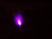
When I press the button coil seems to give off a short burst, one big streamer at least 10cm long and branchy, but doesn't oscillate. (that one at the pic may be even more).
Quick fiddling didn't reveal why.
I tried increasing the CT resistors to 10k ohm - bursts lasted a bit longer and streamers were larger.
Maybe I just don't have enough turns on my CT? I'm using 15+15 right now, still quite crowded on the small core. I wonder will the current get too low then?
The primary I'm using on the coil is about 20 turns, calculated to keep magnetizing current at about 3 amps - I wanted to be safe with it but don't know if I overdone it.
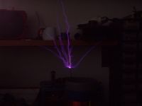
Update: the circuit officially works now. It has apparently been matter only of input voltage - running from 230V isolation transformer gave some nice 7cm CW streamers.
Pics after some replies.
Marko, Sat Dec 08 2007, 10:28PM
I've tried out this circuit today...
Breadboarded, smaller secondary, and a halfbridge of IRFP450's powered from smoothed 325V.
I used 2 UCC's as drivers with scheme I posted.
For startup I used a simple switch to dump a 1nF cap into input of one UCC.
When I press the button coil seems to give off a short burst, one big streamer at least 10cm long and branchy, but doesn't oscillate. (that one at the pic may be even more).
Quick fiddling didn't reveal why.
I tried increasing the CT resistors to 10k ohm - bursts lasted a bit longer and streamers were larger.
Maybe I just don't have enough turns on my CT? I'm using 15+15 right now, still quite crowded on the small core. I wonder will the current get too low then?
The primary I'm using on the coil is about 20 turns, calculated to keep magnetizing current at about 3 amps - I wanted to be safe with it but don't know if I overdone it.

Update: the circuit officially works now. It has apparently been matter only of input voltage - running from 230V isolation transformer gave some nice 7cm CW streamers.
Pics after some replies.
Re: Wireless powering SSTC
uzzors2k, Sun Dec 09 2007, 11:18AM
Looking good Marko, and CW yet!
uzzors2k, Sun Dec 09 2007, 11:18AM
Looking good Marko, and CW yet!
Re: Wireless powering SSTC
Marko, Sun Dec 09 2007, 02:47PM
I'm not happy yet though - I don't believe this circuit will work for pulsed voltage input as it is.
And in order to keep it's properties I would have to use some complex logic I can't bother with. I'll probably have to use either PLL or oscillator trigger - I can make NE 555 to turn the coil on and then be disabled, but this means that coil will turn on simply if I apply mains voltage too.
Hmm...

Re: Wireless powering SSTC
Zum Beispiel, Sun Dec 09 2007, 04:03PM
I'm not sure if I'm qualified to be posting here, but here's my 2 cents:
First I'd try making the feedback transformer with larger amount of turns, maybe 50+50? It could be just that it isn't reaching the threshold voltage?
Secondly, I recommend using a 555 to kick it to oscillation. I haven't had any trouble doing this and it seems reliable.
Also, when you use an interrupter, the gate driver should send out a small pulse every time it's enabled at the beginning of each interrupter cycle, kicking it into oscillation. Atleast I think it does that.
Anyway, keep up the good work

Re: Wireless powering SSTC
Marko, Sun Dec 09 2007, 06:22PM
Actually I reduced the ratio by half by pulling the ground lead again through the core, and got somewhat better. If I get inot need to use such large amounts of turns I may probably just go for a cascaded CT - the base current is still pretty low and I don't think I need that.
If I use oscillator start, the coil will turn on whenever the bridge gets powered and my remote is turned on. I was thinking how to eliminate that possibility and make the coil controllable only by remote.
It would actually work as is if I was running CW, but oscillation would stop if voltage gets too low, unless my feedback is very sensitive (which it apparently isn't).
This would also give free short circuit protection of the output.
I'm thinking if I could stuff in some kind of simple logic to preserve all these ideas.
When inverting and non-inverting UCC's are enabled the output of inverting one is driven permanently high, and if oscillation doesn't start and there is no DC blocking capacitor, mosfets die.
That is one of situations I wanted to avoid.
Just enabling the drivers in my scheme would do nothing because both inputs are held low by the CT. I start the circuit by putting a small pulse, only few microseconds long, into input of one UCC.
I think that is a much more proper way of startup, + I got rid of 5V logic and propagation delays.
Marko, Sun Dec 09 2007, 06:22PM
First I'd try making the feedback transformer with larger amount of turns, maybe 50+50? It could be just that it isn't reaching the threshold voltage?
Actually I reduced the ratio by half by pulling the ground lead again through the core, and got somewhat better. If I get inot need to use such large amounts of turns I may probably just go for a cascaded CT - the base current is still pretty low and I don't think I need that.
Secondly, I recommend using a 555 to kick it to oscillation. I haven't had any trouble doing this and it seems reliable.
If I use oscillator start, the coil will turn on whenever the bridge gets powered and my remote is turned on. I was thinking how to eliminate that possibility and make the coil controllable only by remote.
It would actually work as is if I was running CW, but oscillation would stop if voltage gets too low, unless my feedback is very sensitive (which it apparently isn't).
This would also give free short circuit protection of the output.
I'm thinking if I could stuff in some kind of simple logic to preserve all these ideas.
Also, when you use an interrupter, the gate driver should send out a small pulse every time it's enabled at the beginning of each interrupter cycle, kicking it into oscillation. Atleast I think it does that.
When inverting and non-inverting UCC's are enabled the output of inverting one is driven permanently high, and if oscillation doesn't start and there is no DC blocking capacitor, mosfets die.
That is one of situations I wanted to avoid.
Just enabling the drivers in my scheme would do nothing because both inputs are held low by the CT. I start the circuit by putting a small pulse, only few microseconds long, into input of one UCC.
I think that is a much more proper way of startup, + I got rid of 5V logic and propagation delays.
Re: Wireless powering SSTC
Mates, Sat Feb 09 2008, 09:47PM
It looks that the topic of this thread went little bit far away from the wireless powering and turned to designing problems of an, otherwise very interesting, full bridge SSTC. I think it's a pity because as I can see here Marko just have made a real progress in wireless energy transfer using his coil and I’m sure not only me would like to know more about it…
Marko please, would it be possible to refresh this thread or start a new one giving the explanation to your pictures in the “cool pics†thread?
Thanks Mates
Mates, Sat Feb 09 2008, 09:47PM
It looks that the topic of this thread went little bit far away from the wireless powering and turned to designing problems of an, otherwise very interesting, full bridge SSTC. I think it's a pity because as I can see here
 Marko just have made a real progress in wireless energy transfer using his coil and I’m sure not only me would like to know more about it…
Marko please, would it be possible to refresh this thread or start a new one giving the explanation to your pictures in the “cool pics†thread?
Thanks Mates

Re: Wireless powering SSTC
Marko, Sat Feb 09 2008, 10:16PM
As this thread was primarily about the SSTC design, I think it would be good idea to start a new one... Anyone else of you guys interested?
I also have lots of questions myself (receiver impedance matching, toploads, Tesla's history..) so It's probably time to do something about it?
Re: Wireless powering SSTC
Coronafix, Sun Feb 10 2008, 02:48AM
I think I can speak for nearly everyone and say
"Hell yes we're interested!!"
well I am any way.
Coronafix, Sun Feb 10 2008, 02:48AM
I think I can speak for nearly everyone and say
"Hell yes we're interested!!"
well I am any way.

Re: Wireless powering SSTC
Marko, Mon Feb 11 2008, 02:04PM
Well.. ''where's everybody?'' -fermi
OK, I'll see what I can do, I'd like to cover everything which takes some time.
My professor over here is probably the most amazed - he wants me to patent my ''invention'' O_o
I really need to stay away from the press if I get onto this competition.
This particular SSTC is having some trouble I'd like to fix first, it's main inverter wasn't running in pics on chatting board but little one nearby.
I built some kind of stand for receiver resonator, still have to do capacitive ground points... that's going to be something simple, probably AL foil on PVC sheet, or something like that.
Marko
Marko, Mon Feb 11 2008, 02:04PM
for nearly everyone
Well.. ''where's everybody?'' -fermi
OK, I'll see what I can do, I'd like to cover everything which takes some time.
My professor over here is probably the most amazed - he wants me to patent my ''invention'' O_o
I really need to stay away from the press if I get onto this competition.
This particular SSTC is having some trouble I'd like to fix first, it's main inverter wasn't running in pics on chatting board but little one nearby.
I built some kind of stand for receiver resonator, still have to do capacitive ground points... that's going to be something simple, probably AL foil on PVC sheet, or something like that.
Marko
Print this page