
SSTC questions
Dr. H., Sun Sept 23 2007, 08:19PMAfter the Micro SSTC 1 i decided to build something bigger. So i decideded to use this circuit http://www.ctc-labs.de/html/micro_sstc_2.html .
I was wondering is there anything that must be changed/added to the circuit. I saw a little error - the full wave rectifier on the 12v supply is connected wrong. Also i was wondereng should be there any snubber capacitor across the half bridge or this function is done by the two capacitor connected in series.
Tommorow i will post some pics on my progress.
Huben

Re: SSTC questions
Dr. H., Sun Sept 30 2007, 06:50PM
**Update **
So i finshed the circuit board and hook it up to test it. The cd4046 is generating a square wave (without secondary and antena) about 600khz when the tuning pot is fully counte-clockwise. So hire is the question - when i turn the pot (10k one on the circuit) the frequency starts to change - aqtualy decrizes to about 450khz when the pot is fully clockwise. Is this normal, because i think that this shoud change the phase not the frequency ?
The other problem is with my driver chips - the waveform that i get on the otput of the transformer is more like sinusoidal rather than square weve, but i hope that this will change with the tc4420s (now i was using ICL7667 witch are 2x1.5A each )
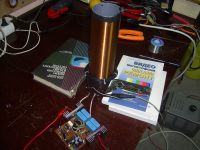
Hire some pictures, please comment any flows in my layout and excuse my english
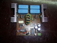
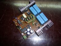


Re: SSTC questions
Dr. H., Mon Oct 01 2007, 03:03PM
Why no one is answering. Am i so booring or my questions are dum
Dr. H., Mon Oct 01 2007, 03:03PM
Why no one is answering. Am i so booring or my questions are dum

Re: SSTC questions
EDY19, Mon Oct 01 2007, 03:59PM
Its nothing about you, and I would attempt to answer, but I've got no experience with PLL circuits- however, your circuit board design looks very nice for a protoboard!
EDY19, Mon Oct 01 2007, 03:59PM
Its nothing about you, and I would attempt to answer, but I've got no experience with PLL circuits- however, your circuit board design looks very nice for a protoboard!
Re: SSTC questions
sehrgut, Mon Oct 01 2007, 05:37PM
I'd answer too, if I'd ever built an SSTC before! I've been working in a rather Luddite mode for the last few years as far as technology goes, so I haven't touched anything with IGBTs or big MOSFETs. Your driver does look luvverly, however! *grin*
Don't feel bad . . . no one's answered my OBIT filtering question either . . . *sniffle*
Re: SSTC questions
Dr. H., Mon Oct 01 2007, 06:03PM
Thanks for the repplyes guys
So todday i received the drive ICs (TC4420). I put them in and tried them. The traces on the scope didn't look very good at all . They are better from the ones with the ICL7667 but i don't think they will lork
  .
.
Dr. H., Mon Oct 01 2007, 06:03PM
Thanks for the repplyes guys

So todday i received the drive ICs (TC4420). I put them in and tried them. The traces on the scope didn't look very good at all
 . They are better from the ones with the ICL7667 but i don't think they will lork
  .
.Re: SSTC questions
Dalus, Mon Oct 01 2007, 06:08PM
Where's the antenna?
Dalus, Mon Oct 01 2007, 06:08PM
Where's the antenna?
Re: SSTC questions
Dr. H., Mon Oct 01 2007, 06:11PM
So hire are the traces. They are the gate - source signals. The top one is with 2 ICs (like on the schematic) and the bottom one is with 4 ICs (2 in paralel). The scope is set to 0.5 micro seconds/div and 10V/div. So what do you think about them ???
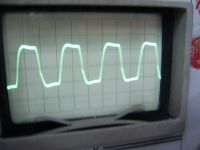
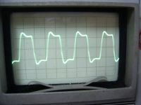
Dr. H., Mon Oct 01 2007, 06:11PM
So hire are the traces. They are the gate - source signals. The top one is with 2 ICs (like on the schematic) and the bottom one is with 4 ICs (2 in paralel). The scope is set to 0.5 micro seconds/div and 10V/div. So what do you think about them ???


Re: SSTC questions
Zum Beispiel, Mon Oct 01 2007, 06:21PM
Those scope shots look fine. You could have a bit faster rise and fall times, though. Some beefier drivers should help with this. Won't probably be a problem tough.
What FETs are you using?
Zum Beispiel, Mon Oct 01 2007, 06:21PM
Those scope shots look fine. You could have a bit faster rise and fall times, though. Some beefier drivers should help with this. Won't probably be a problem tough.
What FETs are you using?
Re: SSTC questions
Dr. H., Mon Oct 01 2007, 08:09PM
The fets are IRF740 - half bridge. Shoud i use 4 or go with 2 drivers. I was concerned about the loses at this high speeds
Dalus - this is cd4046 generating in the moment without the antena (i will add it later when everything is set ) The frequency of the secondary is about 450khz so there will be not a big difference - i think .
.
Also when i use 2 drivers they get a bit warm - i suppose this is OK - wright ?
Dr. H., Mon Oct 01 2007, 08:09PM
The fets are IRF740 - half bridge. Shoud i use 4 or go with 2 drivers. I was concerned about the loses at this high speeds
Dalus - this is cd4046 generating in the moment without the antena (i will add it later when everything is set ) The frequency of the secondary is about 450khz so there will be not a big difference - i think
 .
.Also when i use 2 drivers they get a bit warm - i suppose this is OK - wright ?

Re: SSTC questions
Bauerb2, Mon Oct 01 2007, 09:52PM
while working on my own sstc i felt the gate drivers to get rather hot. i fixed this by adding two electrolyte 22uF caps in series, negatives terminals soldered together, with all this in parralell with a 100nF ceramic cap. this is in series with the tc4429 output. i see on the schem you have that there is one 4.7uF in series. it might be worth a try to try my idea (taken from this site )
)
its worth a try, it made my rise/fall times much quicker. (@ 380kHz sec)
-pz --Andrew
Bauerb2, Mon Oct 01 2007, 09:52PM
while working on my own sstc i felt the gate drivers to get rather hot. i fixed this by adding two electrolyte 22uF caps in series, negatives terminals soldered together, with all this in parralell with a 100nF ceramic cap. this is in series with the tc4429 output. i see on the schem you have that there is one 4.7uF in series. it might be worth a try to try my idea (taken from this site
 )
)its worth a try, it made my rise/fall times much quicker. (@ 380kHz sec)
-pz --Andrew
Re: SSTC questions
Dago, Mon Oct 01 2007, 10:48PM
What kind of decoupling do you have for the gate drive chips? It is absolutely essential to have atleast something like a 100nF ceramic and a 10-40µF tantalum OR low esr electrolytic cap as near as possible to the Vcc and GND pins of the gatedrive chips to achieve fast risetimes. The chips do get hot, mine get too hot to touch comfortably without some airflow at 50% duty cycle.
Dago, Mon Oct 01 2007, 10:48PM
huben Panev wrote ...
So hire are the traces. They are the gate - source signals. The top one is with 2 ICs (like on the schematic) and the bottom one is with 4 ICs (2 in paralel). The scope is set to 0.5 micro seconds/div and 10V/div. So what do you think about them ???


So hire are the traces. They are the gate - source signals. The top one is with 2 ICs (like on the schematic) and the bottom one is with 4 ICs (2 in paralel). The scope is set to 0.5 micro seconds/div and 10V/div. So what do you think about them ???


What kind of decoupling do you have for the gate drive chips? It is absolutely essential to have atleast something like a 100nF ceramic and a 10-40µF tantalum OR low esr electrolytic cap as near as possible to the Vcc and GND pins of the gatedrive chips to achieve fast risetimes. The chips do get hot, mine get too hot to touch comfortably without some airflow at 50% duty cycle.
Re: SSTC questions
CT2, Tue Oct 02 2007, 01:57AM
Yeah as stated previously your gate drive chips will get hot. You need caps on the supply pins (as close as possible). I use a 15uF tantalum and a bigger electrolytic as close as I can get them to the chips and then a 1uF ceramic practically on the pins, even still they run hot. So I had these little heat sinks that fit perfectly on the chip so I just slopped some thermal grease on the chip and stuck the heat sink on. With even a little air flow they run warm but not too hot.
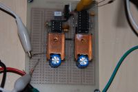
The tantalum is hidden under the heat sink.
About the phase/frequency relationship... well I don't even own a scope so I've never looked at what my PLL is doing, so can't help there.
CT2, Tue Oct 02 2007, 01:57AM
Yeah as stated previously your gate drive chips will get hot. You need caps on the supply pins (as close as possible). I use a 15uF tantalum and a bigger electrolytic as close as I can get them to the chips and then a 1uF ceramic practically on the pins, even still they run hot. So I had these little heat sinks that fit perfectly on the chip so I just slopped some thermal grease on the chip and stuck the heat sink on. With even a little air flow they run warm but not too hot.

The tantalum is hidden under the heat sink.
About the phase/frequency relationship... well I don't even own a scope so I've never looked at what my PLL is doing, so can't help there.
Re: SSTC questions
Dr. H., Tue Oct 02 2007, 05:43AM
Thanks for the replys guys. I've copied the circuit with no changes, so for decoupling on the drive chips i have only one 4.7uF and it is electrolitic
  . Today i will add some tantalum and ceramic condensers. For the decouplink i use 3uF (on the picture of the board the 3 yellow caps put side by side. Are this good ?
Bauerb2 - thenks for the idea. I will trye this too. Is there any chance that the waveform looks like this due to the ferite core (it is NOT the yellow one from ATX. Also could this be due to too much windings on the GTD (15 primary and 2x15 secondary )
CT2 - very nice design, i too may trie something like that
Dr. H., Tue Oct 02 2007, 05:43AM
Thanks for the replys guys.
 I've copied the circuit with no changes, so for decoupling on the drive chips i have only one 4.7uF and it is electrolitic
  . Today i will add some tantalum and ceramic condensers. For the decouplink i use 3uF (on the picture of the board the 3 yellow caps put side by side. Are this good ?
 Bauerb2 - thenks for the idea. I will trye this too. Is there any chance that the waveform looks like this due to the ferite core (it is NOT the yellow one from ATX. Also could this be due to too much windings on the GTD (15 primary and 2x15 secondary )
CT2 - very nice design, i too may trie something like that

Re: SSTC questions
Marko, Tue Oct 02 2007, 10:01AM
On the core you are using you won't need to use more than few turns for 450kHz. See this
Your drivers are also inherently a bit slow. I would use UCC's whenever I could.
Marko, Tue Oct 02 2007, 10:01AM
On the core you are using you won't need to use more than few turns for 450kHz. See this

Your drivers are also inherently a bit slow. I would use UCC's whenever I could.
Re: SSTC questions
Dr. H., Tue Oct 02 2007, 10:12AM
Hi Marko, yes the ICs are slower than the UCCs but i can't find to buy them hire in Bulgaria, so i have no choice
Also in the schematic it is shown to use 16 !!! turns. I also thought that they are too much but after all i winded 15. Hire are the new scope pictures after some changes that the other guys suggested. If you think that i need to change the number of turns i will make it
The top picture is with 2 ICs and the bottom is with 4 (two in paralel ). Shoud i use 4 or could stick to 2 ???
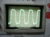
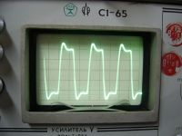
Dr. H., Tue Oct 02 2007, 10:12AM
Hi Marko, yes the ICs are slower than the UCCs but i can't find to buy them hire in Bulgaria, so i have no choice

Also in the schematic it is shown to use 16 !!! turns. I also thought that they are too much but after all i winded 15. Hire are the new scope pictures after some changes that the other guys suggested. If you think that i need to change the number of turns i will make it

The top picture is with 2 ICs and the bottom is with 4 (two in paralel ). Shoud i use 4 or could stick to 2 ???


Re: SSTC questions
Bauerb2, Tue Oct 02 2007, 11:08AM
as far as fall/rise times go in both of those waveforms, i think you'll be fine with two. the rise times are a 'little' sluggish by my view of the 2 IC waveform, but if you could, when you start up your coil at low power, try first with 2 then with 4 to see which one performs better. that's what i'd do.
Re: SSTC questions
Dr. H., Tue Oct 02 2007, 11:26AM
Should i try reducing the number of windings on the gtd ? How this will change the waveform ?
Dr. H., Tue Oct 02 2007, 11:26AM
Should i try reducing the number of windings on the gtd ? How this will change the waveform ?
Re: SSTC questions
Bauerb2, Tue Oct 02 2007, 07:59PM
as you add more turns to the gdt, the waveform starts to look more like a sine wave rather than a square wave. less turns, as i just tested right now (6 turns) , shows the waveform has lost structure and looks like small 6V rounded pulses on the scope. the driver IC's heated up incredibly (burnt my finger) in seconds. this was tested with 2 tc4420's with halfbridge irfp460's and then tested again with a full bridge of 460's. each mosfet has a 10 ohm gate resistor.
it seems i am having some insane trouble with my gdt, i can never get a clean signal. it could be the fact im trying to drive a full bridge with one gdt with one primary, and only 2 driver ic (6 amp each). hehe perhaps, but i dont have 2 similar toroid inductors to use... oh well
wish you luck
-andrew
Re: SSTC questions
Dr. H., Tue Oct 02 2007, 10:04PM
Hi Bauerb2 i actually tried reducing the winding on the gdt. I am now using only 7 turns (compared to the initial 15) and the waveform become litle bit better and the driver chips are running cooler, much cooler than before. I also reduced the gtd decoupling capacitor to 470nF and that improved the waveform further (strangely, any one for explanation ??? ) Tommorow morning i will post the scope traces )
Re: SSTC questions
Dr. H., Wed Oct 03 2007, 07:09AM
So hire is the last scope traces. I won't be trying to make them faster (they are now in the range of 80nS ). So whay do you yhink guys
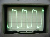
Dr. H., Wed Oct 03 2007, 07:09AM
So hire is the last scope traces. I won't be trying to make them faster (they are now in the range of 80nS ). So whay do you yhink guys


Re: SSTC questions
Bauerb2, Wed Oct 03 2007, 11:02AM
very nice. are these with the paralleled drivers or just the single? even so, these pulses look fine to me. now if only i could get that sort of result from my gdt i would be happy. i keep getting a voltage droop of 3-4 volts and the waves look terrible. i've tried both increasing and decreasing the gdt windings, and increasing/ decreasing the coupling cap. i have yet to find a certain direction to aim for that will make it better.
what was your final choice value for the decoupling caps? and what ic's did you use: the tc4420 or the ICL7667?
--pz-- andrew
Re: SSTC questions
Dr. H., Wed Oct 03 2007, 11:34AM
Hi Bauerb2 . On the scope trace above i use paralleled drivers (when i use single the waveform is not much different - just a little bit slower rise and fall times). I use tc4422 (in the schetatic is tc4420 ). Decoupling is 470nF. I first tried with ICL7667 but they are very slow (compared to the TCs) and have only 3A pic. Why don't you post some pics of your signal ?
Also what kind of feritte core are you using ?
Dr. H., Wed Oct 03 2007, 11:34AM
Hi Bauerb2
 . On the scope trace above i use paralleled drivers (when i use single the waveform is not much different - just a little bit slower rise and fall times). I use tc4422 (in the schetatic is tc4420 ). Decoupling is 470nF. I first tried with ICL7667 but they are very slow (compared to the TCs) and have only 3A pic. Why don't you post some pics of your signal ?
 Also what kind of feritte core are you using ?
Re: SSTC questions
ragnar, Wed Oct 03 2007, 01:17PM
A 'droop' from the start to the end of the pulse generally indicates saturation -- try doubling the number of windings or running at a higher frequency to see if the droops start to straighten out.
ragnar, Wed Oct 03 2007, 01:17PM
Bauerb2 wrote ...
...i keep getting a voltage droop of 3-4 volts and the waves look terrible. i've tried both increasing and decreasing the gdt windings, and increasing/ decreasing the coupling cap...
...i keep getting a voltage droop of 3-4 volts and the waves look terrible. i've tried both increasing and decreasing the gdt windings, and increasing/ decreasing the coupling cap...
A 'droop' from the start to the end of the pulse generally indicates saturation -- try doubling the number of windings or running at a higher frequency to see if the droops start to straighten out.
Re: SSTC questions
Bauerb2, Wed Oct 03 2007, 07:51PM
the frequency its running at is 50khz slower than the actual fres of the sstc secondary (fres = 330kHz. The test quare wave freq i am using = 280kHz) so i can try that now i suppose (for some reason the freq changed on me since i built the test circuit.) anyway.. i have tried sooo many different numbers of turns. so check it out.
turns
10-14 = drooped madness
15-20 = less droop, slower rise/fall (not sure of exact time, scope isnt tuned properly)
20-24 = almost perfect, but the rise/fall times are relatively slow.
30+ = starting to resemble a sine wave.
since i am lazy and dont feel like ordering a new core, i used one from a computer psu. dimensions are 2.7cm outer diamter, with a 1.2cm height. inner diamter is 1.4cm.
here are some pics:
first one is the gate waveform with 22 turns drivign a full bridge; each gate having a 10ohm res. (5v/div 1uS/div again, dont trust these) with temporary coupling caps total charge of 1.68uF (works a little better than the series electrolytic caps i mentioned b4) the waveform has gotten better i suppose..
second is the setup which includes the 555 running very close to 50% at around 280khz, there's the logic nand chip (only to invert signal) and then the 4 tc4420's running 2 high 2 low parallel.
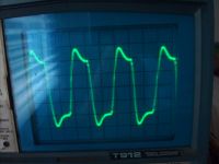
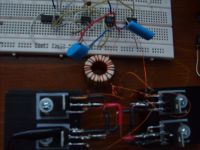
if i am testing this wrong or wiring something weird, please tell me, it will help.
thanks
-Andrew
Bauerb2, Wed Oct 03 2007, 07:51PM
the frequency its running at is 50khz slower than the actual fres of the sstc secondary (fres = 330kHz. The test quare wave freq i am using = 280kHz) so i can try that now i suppose (for some reason the freq changed on me since i built the test circuit.) anyway.. i have tried sooo many different numbers of turns. so check it out.
turns
10-14 = drooped madness
15-20 = less droop, slower rise/fall (not sure of exact time, scope isnt tuned properly)
20-24 = almost perfect, but the rise/fall times are relatively slow.
30+ = starting to resemble a sine wave.
since i am lazy and dont feel like ordering a new core, i used one from a computer psu. dimensions are 2.7cm outer diamter, with a 1.2cm height. inner diamter is 1.4cm.
here are some pics:
first one is the gate waveform with 22 turns drivign a full bridge; each gate having a 10ohm res. (5v/div 1uS/div again, dont trust these) with temporary coupling caps total charge of 1.68uF (works a little better than the series electrolytic caps i mentioned b4) the waveform has gotten better i suppose..
second is the setup which includes the 555 running very close to 50% at around 280khz, there's the logic nand chip (only to invert signal) and then the 4 tc4420's running 2 high 2 low parallel.


if i am testing this wrong or wiring something weird, please tell me, it will help.
thanks
-Andrew
Re: SSTC questions
Experimentonomen, Wed Oct 03 2007, 08:21PM
Do us a favor and replace that iron powder dc filter with a proper ferrite toroid.
You won´t regret it, you´ll get so much better performance and cooler ucc´s.
Experimentonomen, Wed Oct 03 2007, 08:21PM
Do us a favor and replace that iron powder dc filter with a proper ferrite toroid.
You won´t regret it, you´ll get so much better performance and cooler ucc´s.
Re: SSTC questions
Bauerb2, Wed Oct 03 2007, 09:36PM
haha yup i knew someone would immediately destroy my hopes and dreams and make me feel bad. i knew before i even wound it that it wouldn't work as good as it should. have mercy, for this is my first sstc and i am a little new.
i have used these toroids b4 in other projects like a battery desulfator and others, and i assumed they were all the same. i knew there were different types of cores, but i didnt know which kind this one was.
w/e
thanks hfsstc i will replace it as soon as possible.
pz - Andrew
Re: SSTC questions
Dr. H., Thu Oct 04 2007, 05:33AM
When i was starting to built my very first SSTC (whcih didn't work at all ) i was also trying to use this type of cores (at that time i didn't know that they are not suited for that kind of purpose). My waveforms looked exactly like yours, my core was warming up a lot, and my drive tranzistors were also heating a lot). I've changed the core and everything worked perfekt. Just order some, or pull ot from something. I have used cores from microwave filters (i dont know how good is the core but up to 300khz they were perfect
  )
)
Dr. H., Thu Oct 04 2007, 05:33AM
When i was starting to built my very first SSTC (whcih didn't work at all
 ) i was also trying to use this type of cores (at that time i didn't know that they are not suited for that kind of purpose). My waveforms looked exactly like yours, my core was warming up a lot, and my drive tranzistors were also heating a lot). I've changed the core and everything worked perfekt. Just order some, or pull ot from something. I have used cores from microwave filters (i dont know how good is the core but up to 300khz they were perfect
  )
)Re: SSTC questions
Dr. H., Thu Oct 04 2007, 08:19AM
Last night i started testing the bridg.W With no load there is a little ringing on 17v - first picture (i think normal). With a smal lamp (12v) for load it worked perfekt - second picture. So i decidet to tested it with a 300 DC and a 75W lamp for load. I connected the variav through a 500W bulb for protection and tryed. I increased the voltage gradualy and everything worked great until i hit 280v DC - then one of the transistors shorted. When i touched them they were exptremely hot. Today i replaced the bwoln transistor, and i saw something interesting - the transistor had become so hot that it had melted the nylon busher (i don't now how it is called) that separates the screw from the metal plate of the transistor. I've changed the thermal pad with silica and now works better but it will neew bigger radiators .
.
After replacing the transistor i connected the primary, put the secondary and have a go. With input of 36V and 2.4A it gave about 2sm (0.8 inch) of streamers and about 4sm to grounded object. The transistors were getting a little warm.
So i hooked the scope to the primary and saw something interesting on the scope - the third picture. Excuse for the bad picture, the flash have ruind it . Could someone tell me why it is looking like that
After that i hooked it to the variak and have a go. At about 80v AC, half wave rectified it gave about 7sm of streamers, but the transistors started getting very hot so i stoped the test.
So the question now is why the waveforms look like that ???
On the picture the streamers look little but actualy the are longer
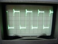
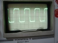
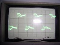
Dr. H., Thu Oct 04 2007, 08:19AM
Last night i started testing the bridg.W With no load there is a little ringing on 17v - first picture (i think normal). With a smal lamp (12v) for load it worked perfekt - second picture. So i decidet to tested it with a 300 DC and a 75W lamp for load. I connected the variav through a 500W bulb for protection and tryed. I increased the voltage gradualy and everything worked great until i hit 280v DC - then one of the transistors shorted. When i touched them they were exptremely hot. Today i replaced the bwoln transistor, and i saw something interesting - the transistor had become so hot that it had melted the nylon busher (i don't now how it is called) that separates the screw from the metal plate of the transistor. I've changed the thermal pad with silica and now works better but it will neew bigger radiators
 .
.After replacing the transistor i connected the primary, put the secondary and have a go. With input of 36V and 2.4A it gave about 2sm (0.8 inch) of streamers and about 4sm to grounded object. The transistors were getting a little warm.
So i hooked the scope to the primary and saw something interesting on the scope - the third picture. Excuse for the bad picture, the flash have ruind it
 . Could someone tell me why it is looking like that
After that i hooked it to the variak and have a go. At about 80v AC, half wave rectified it gave about 7sm of streamers, but the transistors started getting very hot so i stoped the test.
So the question now is why the waveforms look like that ???
On the picture the streamers look little but actualy the are longer


Re: SSTC questions
Marko, Thu Oct 04 2007, 10:58AM
Have you got the feedback to work? Are you sure PLL isn't locking to a wrong mode there?
The way your gate waveform rings just doesn't look good to me.
You need to make sure your coil's frequency falls into locking range of the PLL. That's why you need to adjust those pin 11/12 resistors after all.
Re: SSTC questions
Dr. H., Thu Oct 04 2007, 11:34AM
Hi Marko
The PLL is working. It is traking the exact frequency (about 500khz) . This are pictures of the output of the half bridge (top - no load, middle with lamp as load, third primarry with secondary for load.
So the question is for the 3rd. Should the voltage in the primary look like that (i don think so )
)
Dr. H., Thu Oct 04 2007, 11:34AM
Hi Marko
The PLL is working. It is traking the exact frequency (about 500khz) . This are pictures of the output of the half bridge (top - no load, middle with lamp as load, third primarry with secondary for load.
So the question is for the 3rd. Should the voltage in the primary look like that (i don think so
 )
)Re: SSTC questions
Dr. H., Sat Oct 06 2007, 06:27AM
**UPDATE**
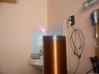
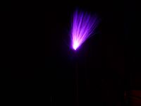
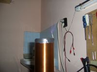
Hi guys, after a lot of fiddling i finaly got it to work properly. It si producing about 13sm of streamers (5.2 inch ) and about 15-16sm to grounded target . Thanks for your help guys. Hire are some pictures of the streamers (i don't know why but on the picture they look shorter than they actulay are.
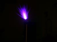
Dr. H., Sat Oct 06 2007, 06:27AM
**UPDATE**
Hi guys, after a lot of fiddling i finaly got it to work properly. It si producing about 13sm of streamers (5.2 inch ) and about 15-16sm to grounded target
 . Thanks for your help guys. Hire are some pictures of the streamers (i don't know why but on the picture they look shorter than they actulay are.


Re: SSTC questions
Zum Beispiel, Sat Oct 06 2007, 10:40AM
Good job! Now the real fun begins.
What kind of power are you using (Fullwave/Fullwave + filtering/Halfwave)? Experiment with different inputs. Halfwave rectification usually gives longer sparks than fullwave. Try taking some turns off the primary, try moving it up and down. Try putting a topload on it.
Push it till it blows, then back up a little

Re: SSTC questions
Bauerb2, Sat Oct 06 2007, 04:41PM
that is awesome huben. are the mosfets still overheating or do they run cooler now? You should definitely try a topload, i want to see how much power you'll get from this coil, it looks promising.
as a side question related to earlier in the thread, does anybody know where i can buy a ferrite gdt toroid that has a high permeability? i've checked everywhere but i can't seem to find the right one (there's so many different materials and sizes). im planning on powering a full bridge with one, but if i can get two toroids, i'll seperate the gdt into 2 parts. Where have you all bought your gdt toroids?
Anyway..once i get the gdt completed i can finish the whole coil in a few hours.
thanks for the help, nice coil ruben
pz - Andrew
Re: SSTC questions
Zum Beispiel, Sat Oct 06 2007, 04:47PM
Failing that, good ferrites can be salvaged from most broken eletronics thingies. If you have a scope you can check that it gives clean waveforms, just needs more work than buying a core that is known to work.
Zum Beispiel, Sat Oct 06 2007, 04:47PM
Bauerb2 wrote ...
as a side question related to earlier in the thread, does anybody know where i can buy a ferrite gdt toroid that has a high permeability? i've checked everywhere but i can't seem to find the right one (there's so many different materials and sizes). im planning on powering a full bridge with one, but if i can get two toroids, i'll seperate the gdt into 2 parts. Where have you all bought your gdt toroids?
Anyway..once i get the gdt completed i can finish the whole coil in a few hours.
I bought the ones Thedatastream recommends on his site from Farnell. They don't cost that much and perform very well. You can ask from some eletronics shop if they have an account there and if they can order some for you.as a side question related to earlier in the thread, does anybody know where i can buy a ferrite gdt toroid that has a high permeability? i've checked everywhere but i can't seem to find the right one (there's so many different materials and sizes). im planning on powering a full bridge with one, but if i can get two toroids, i'll seperate the gdt into 2 parts. Where have you all bought your gdt toroids?
Anyway..once i get the gdt completed i can finish the whole coil in a few hours.
Failing that, good ferrites can be salvaged from most broken eletronics thingies. If you have a scope you can check that it gives clean waveforms, just needs more work than buying a core that is known to work.
Re: SSTC questions
Dr. Dark Current, Sat Oct 06 2007, 05:09PM
Dr. Dark Current, Sat Oct 06 2007, 05:09PM
Bauerb2 wrote ...
as a side question related to earlier in the thread, does anybody know where i can buy a ferrite gdt toroid that has a high permeability? i've checked everywhere but i can't seem to find the right one (there's so many different materials and sizes). im planning on powering a full bridge with one, but if i can get two toroids, i'll seperate the gdt into 2 parts. Where have you all bought your gdt toroids?
Anyway..once i get the gdt completed i can finish the whole coil in a few hours.
thanks for the help, nice coil ruben
pz - Andrew
I got two big ferrite toroids great for gdt from old switching power supply from a photocopier, some good ones are also sometimes in old tv's and you can always use the core from an atx power supply transformer, it works well for a gdtas a side question related to earlier in the thread, does anybody know where i can buy a ferrite gdt toroid that has a high permeability? i've checked everywhere but i can't seem to find the right one (there's so many different materials and sizes). im planning on powering a full bridge with one, but if i can get two toroids, i'll seperate the gdt into 2 parts. Where have you all bought your gdt toroids?
Anyway..once i get the gdt completed i can finish the whole coil in a few hours.
thanks for the help, nice coil ruben
pz - Andrew
Re: SSTC questions
Dr. H., Sat Oct 06 2007, 05:25PM
Hi to all end thenks fot the help guys, if weren't you i woudn't have gone so far
So for the torroids i get them from microwave ovens - they have a some sort of filter. The toroids are great for gtds. In this coil i actualy use the same, and you can see tha waveforms on the previous page.
So now for the coil. Today i spent about 4 hours of experimenting with the primary and i found some interesting thing.
1st - when i use helical style primary i get smaller streamers and my tranzistor get very warm, so now i use something like a bunch of wires tightened togheter with straps.
2nd - when i increase the coupling, the streamers become shorter, but hotter, more like flame, i had to change the breakout point to tungsten, and the transistors are getting very hot.
3rd - when i use smaller coupling, and 6 turns i get the longest streamers and the tranzistors are only slightly warm
BUT hire comes the most strange to me problem. In the 3rd situation when i turn on the coil i get about 17-18sm of streamers but for about 3-4 seconds, after that they become shorter and fatter, more like flame (i am using half way rectified, so i find this strange
  ). Also i noticed that this happens (according to me, but if anyone has other informatio PLEASE write it ) when the breakout point become hot.
Please tell what you think about that. And one last question - how do you guys determine coupling ???
???
Dr. H., Sat Oct 06 2007, 05:25PM
Hi to all end thenks fot the help guys, if weren't you i woudn't have gone so far

So for the torroids i get them from microwave ovens - they have a some sort of filter. The toroids are great for gtds. In this coil i actualy use the same, and you can see tha waveforms on the previous page.
So now for the coil. Today i spent about 4 hours of experimenting with the primary and i found some interesting thing.
1st - when i use helical style primary i get smaller streamers and my tranzistor get very warm, so now i use something like a bunch of wires tightened togheter with straps.
2nd - when i increase the coupling, the streamers become shorter, but hotter, more like flame, i had to change the breakout point to tungsten, and the transistors are getting very hot.
3rd - when i use smaller coupling, and 6 turns i get the longest streamers and the tranzistors are only slightly warm

BUT hire comes the most strange to me problem. In the 3rd situation when i turn on the coil i get about 17-18sm of streamers
 but for about 3-4 seconds, after that they become shorter and fatter, more like flame (i am using half way rectified, so i find this strange
  ). Also i noticed that this happens (according to me, but if anyone has other informatio PLEASE write it ) when the breakout point become hot.
 Please tell what you think about that. And one last question - how do you guys determine coupling
 ???
??? Re: SSTC questions
Bauerb2, Sat Oct 06 2007, 05:36PM
maybe the heat from the breakout is creating a little 'pocket' of heat around it, and current likes to travel through this heat region. a few years back i arced a flyback xformer, run at a low duty cycle, which normally is just a sequnece of sparks *taptaptapta*, but when i short it out through a candle flame the seperate sparks combined into a fat little arc.
i could be wrong, but w/e.
anyway, thatnks for the help guys abotu the toroids. i've checked through pretty much all my electronic junk pile and found nothing. i had a few toroids from a couple of computer psu's but according to some people, this is not ferrite, but powdered iron, which apparently is not good for gdt use. ill look on the internet more, or find some junk to tear apart
thanks all
-Andrew
Bauerb2, Sat Oct 06 2007, 05:36PM
maybe the heat from the breakout is creating a little 'pocket' of heat around it, and current likes to travel through this heat region. a few years back i arced a flyback xformer, run at a low duty cycle, which normally is just a sequnece of sparks *taptaptapta*, but when i short it out through a candle flame the seperate sparks combined into a fat little arc.
i could be wrong, but w/e.
anyway, thatnks for the help guys abotu the toroids. i've checked through pretty much all my electronic junk pile and found nothing. i had a few toroids from a couple of computer psu's but according to some people, this is not ferrite, but powdered iron, which apparently is not good for gdt use. ill look on the internet more, or find some junk to tear apart

thanks all
-Andrew
Re: SSTC questions
Dr. H., Sun Oct 07 2007, 03:49PM
So i complited the coil interely and tested it. It ran for 5 min without any problems, the transistors were slightly warm, but then, in the exact moment i turned it off the fuses blown and the two transistor went dead. Previously a had the same problem - they died in the moment i turned on the coil, but at that time i thought that this was caused by me. So the question is why they die HELP
HELP
Dr. H., Sun Oct 07 2007, 03:49PM
So i complited the coil interely and tested it. It ran for 5 min without any problems, the transistors were slightly warm, but then, in the exact moment i turned it off the fuses blown and the two transistor went dead. Previously a had the same problem - they died in the moment i turned on the coil, but at that time i thought that this was caused by me. So the question is why they die
 HELP
HELPRe: SSTC questions
Bennem, Sun Oct 07 2007, 04:06PM
When turning off your supply voltages,
I sometimes think its a good idea to turn off the bridge supply
voltage first and if you have storage caps, make sure they are discharged,
then secondly turn off the drivers voltage.
Reverse the procedure when turning on your coil.
as sometimes when you just turn off all voltages at once may cause
your driver to inadvertantly turn on your bridge and blow IGBT's.
Just a thought.
Re: SSTC questions
Bauerb2, Sun Oct 07 2007, 04:21PM
my half bridge flyback driver had those problems too. i had to make sure i turned on the driver circuitry before the bridge voltage was applied. If not the mosfets were ruined...
do these toroids look good for gdt use?
it was funny because i googled ferrite toroids and got this site, which was based in pittsburgh PA, only 20 miles from my house. hah
Bauerb2, Sun Oct 07 2007, 04:21PM
my half bridge flyback driver had those problems too. i had to make sure i turned on the driver circuitry before the bridge voltage was applied. If not the mosfets were ruined...
do these toroids look good for gdt use?

it was funny because i googled ferrite toroids and got this site, which was based in pittsburgh PA, only 20 miles from my house. hah
Re: SSTC questions
Dr. H., Sun Oct 07 2007, 05:28PM
Hi Bauerb2. I think that toroids will do the job, but let some of the more experienced member tell theyr opinion too. For the blowing tranzistors i was also thinking about the same cause. I was thinking to use steve's sstc1 soft start circuit. I holp that he will give some information why this is happening ???
Re: SSTC questions
Bauerb2, Mon Oct 08 2007, 08:03PM
after some research i found the W material ferrite toroid i linked to above wont do very well at 330kHz. So i stepped down to the J material (also called 75?). it is practically the smae thing, but diff material and perm. rating. i think it will suit well for 330kHz.
im still not sure how to order parts from Magnetics® though....
good luck all
-Andrew
Bauerb2, Mon Oct 08 2007, 08:03PM
after some research i found the W material ferrite toroid i linked to above wont do very well at 330kHz. So i stepped down to the J material (also called 75?).
 it is practically the smae thing, but diff material and perm. rating. i think it will suit well for 330kHz.
im still not sure how to order parts from Magnetics® though....

good luck all
-Andrew
Print this page