
CCPS (Capacitor Charging Power Supply)
Finn Hammer, Thu Aug 23 2007, 09:41PMAll,
I am building a medium/large Tesla coil together with Daniel Uhrenholt, a fellow coiler and toolmaker here in Denmark.
During a period, where progress was slow, due to me having other commitments, Daniel submitted: I am going to have a go at a CCPS for the coil, I`ve seen Marco`s and Ward has done some work on it also.
I thought:"Yeah, right" and forgot about it, but then some promising videos showed up on youtube


And so I thought Hey, this looks good, I`d better pay attention.
So during the next weekend, we got a microsim model set up.

I had some of the big cores lying around, waiting for an opportunity like this, and we started to make some measurements on them.
By applying 40kHz to them, turning up the voltage and watching the triangular current curve, we looked for the point where the curve got an upward slope. This was also the point where they got warm, indicating beginning saturation.
This happened at 50volts/turn.
We also made mock up windings to measure the leakage inductance of the transformer, and it turned out to be 58uH.
Plugging the numbers into microsim, with a series capacitor of 68nF, a resonant frequency of 80kHz revealed some nice numbers:
At the start of the charging cycle, 19A at the end 39A for 15Arms
Drawing this kind of current from a 560V supply gives 8400VA and with 2 cores available, a 16KVA supply looked feasible.
After this we concluded that there was only one thing to do: Built the damn thing.
I had a pcb for a plasma sonic leftover from another life, and we decided that it would be a good platform for the development stage, until we had a working design. I severed it in half,
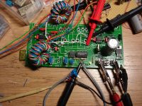
dumping the H-bridge section, and modified it to start and stop in syc. with the oscillator.
IGBT``s are not cheap, and sifting trough the maze of 20USD+ devices, I stumbled upon this little beauty:

And at 2USD I decided to build 2 bridges with 8 devices in each.
Since I figured not to change one defective IGBT in the case of a bridge failure, I went for a compact design.
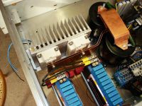
A HP214A was gutted and stuffed with quality parts. 3phase inlet, resistive softstart, timer bypassed. dual 3300uF smoothing caps and bleeders. The transformers and bridges. After some shuffling around, this is the current stage:
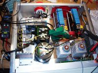
It does work!
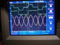
and this is still with the secondary shorted securely.
I know what you are thinking! You are sitting at your little monitors thinking:
Show us your gate waveforms! Show them to us, so that we can tell you that you are a schmuck!

I won``t disappoint you of course.
With a 22ohm gate resistor, there is no overshoot at the zero transition, and the gate charge gets transferred in a little over 300Sn
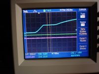
As soon as voltage is aplied, things get a bit more ragged, with a nasty 20mHz ripple.
I am starting to run into measurement difficulties, such as different output from a Pearson 2100 and a Tek P6021/134. The latter follows the gate signal with greater fidelity than the pearson.
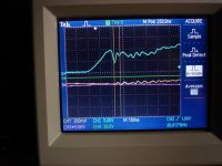
With 15Arms flowing trough the bridges, and a voltage drop across each device of 1.9V, one would assume 3.8 x 15 = 57W dissiption, and the finns get hot in about 30sec, so I guess a big fan has to be installed.
This weekend, Daniel and I are going to work on a voltage probe, so that we can set the desired output voltage.
We also intend to pass the trigger signal from the trigger generator trough this supply, so that we can derive a delay, to kep it disabled during the coils ringdown, and so that it starts charging the cap after the BRISG has quenched.
And perhaps try it out on a jacobs ladder.
We invite you all to comment, and in particular help us add protective circuitry, to keep this beauty running.
Cheers, Finn and Daniel
Re: CCPS (Capacitor Charging Power Supply)
Steve Ward, Fri Aug 24 2007, 05:15AM
Nice work so far guys.
For snubbing the GDT ringing, i found that around 5-10 ohms on the *primary* side of the GDT was all that was needed (no secondary side gate resistance). This produces very clean waveforms.
My CCPS currently produces a very healthy arc and about 20KV peak output voltage from a voltage doubler. It works great for charging up my beastly 5kJ 12kV pulse cap.
It should run a TC great as well, just be sure to stick some sort of output filter on the thing. I had some strange issues when running a spark gap coil. I think a SISG will be a little nicer than a spark gap system anyway.
Also, you might still want to watch for core saturation. The way i did it was just put another few turns of wire on the core and scope it. As you bring up the voltage, you should get a good idea of the odd voltage waveform. If you begin to saturate, you will likely see the voltage drop off to zero. I think the inverter is pretty well protected against saturation effects since the magnetizing inductance is typically shorted out anyway (which is basically what happens for saturation). Only thing is that the core gets very hot!
Keep us posted!
Re: CCPS (Capacitor Charging Power Supply)
Marko, Fri Aug 24 2007, 11:59AM
Hi Finn
Awesome project guys. You always find those beautiful metal cases for these things.
Any pics of the monster transformer for me?
For 16kW although I would be worried about those heatsink size.. those two look really wimpy even for like 99% efficiency, make sure to do something in order not to overheat the IGBT's.
Other thing could be bad power factor.. But it's natural outcome of need for smooth output.
I imagine it could only be practically helped by a humongous boost converter like Steve's.
Steve: I always wondered how much sense does it make to use all the diode-resistor mess in gate drive.
If my transformer is made well enough, I thought I can avoid gate Zeners after all, just by using clamp-to-rail Schottky diodes on driver outputs?
Still if I want dead time (which you guys have plenty of here) I need separate resistors and diodes for each gate. (Meh.)
Re: CCPS (Capacitor Charging Power Supply)
Finn Hammer, Fri Aug 24 2007, 05:11PM
I was eager to try this out, but it didn`t work with my setup.
I tried with 10, 5 and 3.3 ohms, about the same results. Shown here are the 5 ohms traces.
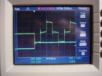
Here is a scope shot of the unloaded gate voltage
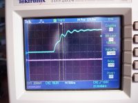
The miller plateau is not distinctly visible.
This shot shows the gate with voltage on the bridge
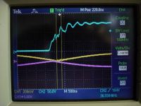
The yellow trace shows the corresponding current curve. The turn on is delayed relative to the other bridge.
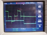
Next pic. shows the current waveform, the yellow one.
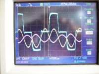
To me, it says that the IGBT is not conducting fully. The leading current pulse is smaller in amplitude than the freewheling one.
And the bridge is heating more.
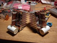
To the left is a prototype of the homemade fiberglass former. This is covered with mylar and other dielectric from stock.
Primary wire is 14 turns 1.1 x 5 mm flat wire, over electrostatic shield. Sec is 0.75mm wire. We may rewind this for more clearance at the hot end.
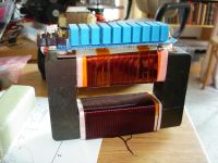
The cooling finns, yeah, I wish I had thought about that before I made it. I just grabbed a sample, without making any calculations.
Silly Me.
Cheers, Finn Hammer
Finn Hammer, Fri Aug 24 2007, 05:11PM
Steve Ward wrote ...
For snubbing the GDT ringing, i found that around 5-10 ohms on the *primary* side of the GDT was all that was needed (no secondary side gate resistance). This produces very clean waveforms.
For snubbing the GDT ringing, i found that around 5-10 ohms on the *primary* side of the GDT was all that was needed (no secondary side gate resistance). This produces very clean waveforms.
I was eager to try this out, but it didn`t work with my setup.
I tried with 10, 5 and 3.3 ohms, about the same results. Shown here are the 5 ohms traces.
Here is a scope shot of the unloaded gate voltage

The miller plateau is not distinctly visible.
This shot shows the gate with voltage on the bridge

The yellow trace shows the corresponding current curve. The turn on is delayed relative to the other bridge.
Next pic. shows the current waveform, the yellow one.

To me, it says that the IGBT is not conducting fully. The leading current pulse is smaller in amplitude than the freewheling one.
And the bridge is heating more.
Marko wrote ...
Hi Finn
Any pics of the monster transformer for me?
For 16kW although I would be worried about those heatsink size.. those two look really wimpy even for like 99% efficiency, make sure to do something in order not to overheat the IGBT's.
Hi Finn
Any pics of the monster transformer for me?
For 16kW although I would be worried about those heatsink size.. those two look really wimpy even for like 99% efficiency, make sure to do something in order not to overheat the IGBT's.
To the left is a prototype of the homemade fiberglass former. This is covered with mylar and other dielectric from stock.
Primary wire is 14 turns 1.1 x 5 mm flat wire, over electrostatic shield. Sec is 0.75mm wire. We may rewind this for more clearance at the hot end.

The cooling finns, yeah, I wish I had thought about that before I made it. I just grabbed a sample, without making any calculations.
Silly Me.
Cheers, Finn Hammer
Re: CCPS (Capacitor Charging Power Supply)
Marko, Fri Aug 24 2007, 05:56PM
Finn you are brilliant, and transformer with this flat wire is wicked cool.
I'm eager to see you progressing.
I wondered if there is actually a benefit from having the primary under the secondary.
Few days ago I was drawing arcs from similarly constructed transformer, except on a flyback core and hard-switched mosfet halfbridge.
It was curious how with no ballast I couldn't get more then some 200-300W (very roughly) into the arc, even after I ramped the frequency to 100kHz and V/turn quite up.
At first I used primary ballast what I thought as reasonable, but in the end without it and no gaps I couldn't get satisfactionary amount of power through the core, even though setup should be good for like kW of power at least. (mosfets got barely over room temperature)
It appears that leakage inductance is really a big limiting factor, what can be done for it?
Re: CCPS (Capacitor Charging Power Supply)
Steve Ward, Fri Aug 24 2007, 06:54PM
Are you saying this was caused by using a resistor on the primary of the GDT? Well, surely this can change the switching speed of the IGBT, but they are definitely turning on completely for nearly all of the half-cycle. My CCPS also had one current peak smaller than the other. I never really figured out exactly why that happened, but my Pspice sim often produced that same result. BTW, i see the same non-uniformity in current peaks in your original scope shot from post #1.
One reason the primary resistance (vs secondary side gate resistors) might be somewhat desirable is that in the event of a IGBT failure and assuming it fails with all pins shorted, you end up killing the gate drive to the other devices. This is good since it prevents the other switch in the half-bridge from switching ON shorting out the DC bus. In this case, most of the gate drive voltage is dropped across the primary resistor, rather than only the secondary gate resistor. Of course, i dont think ive more than 1 failure since implementing the SLR topology, and that one failure was a single IGBT that had managed to arc through the sil-pad isolator to the heatsink (this happened while powering a SGTC and using no filter between supply and TC).
Well, first, its kVA (not kW), and this distinction is very important for the SLR CCPS because it inherently has a lot of reactive power and a lot less real power (much like the "ZVS flyback driver"). But i agree, the 57W figure is pretty optimistic.
Steve Ward, Fri Aug 24 2007, 06:54PM
To me, it says that the IGBT is not conducting fully. The leading current pulse is smaller in amplitude than the freewheling one.
And the bridge is heating more.
Are you saying this was caused by using a resistor on the primary of the GDT? Well, surely this can change the switching speed of the IGBT, but they are definitely turning on completely for nearly all of the half-cycle. My CCPS also had one current peak smaller than the other. I never really figured out exactly why that happened, but my Pspice sim often produced that same result. BTW, i see the same non-uniformity in current peaks in your original scope shot from post #1.
One reason the primary resistance (vs secondary side gate resistors) might be somewhat desirable is that in the event of a IGBT failure and assuming it fails with all pins shorted, you end up killing the gate drive to the other devices. This is good since it prevents the other switch in the half-bridge from switching ON shorting out the DC bus. In this case, most of the gate drive voltage is dropped across the primary resistor, rather than only the secondary gate resistor. Of course, i dont think ive more than 1 failure since implementing the SLR topology, and that one failure was a single IGBT that had managed to arc through the sil-pad isolator to the heatsink (this happened while powering a SGTC and using no filter between supply and TC).
For 16kW although I would be worried about those heatsink size.. those two look really wimpy even for like 99% efficiency, make sure to do something in order not to overheat the IGBT's.
Well, first, its kVA (not kW), and this distinction is very important for the SLR CCPS because it inherently has a lot of reactive power and a lot less real power (much like the "ZVS flyback driver"). But i agree, the 57W figure is pretty optimistic.
Re: CCPS (Capacitor Charging Power Supply)
Finn Hammer, Fri Aug 24 2007, 07:18PM
About leakage inductance: If you resonate it with a series capacitor, and drive it at 1/2 the resonant frequency, with 50% duty cycle, it becomes your friend.
Read Marco Denicolai`s thesis for a full coverage of the CCPS topology.

Cheers, Finn Hammer
Finn Hammer, Fri Aug 24 2007, 07:18PM
Marko wrote ...
It appears that leakage inductance is really a big limiting factor, what can be done for it?
It appears that leakage inductance is really a big limiting factor, what can be done for it?
About leakage inductance: If you resonate it with a series capacitor, and drive it at 1/2 the resonant frequency, with 50% duty cycle, it becomes your friend.
Read Marco Denicolai`s thesis for a full coverage of the CCPS topology.

Cheers, Finn Hammer
Re: CCPS (Capacitor Charging Power Supply)
Steve Conner, Fri Aug 24 2007, 07:24PM
The second half-cycle is always smaller than the first because you're looking at the beginning of a ringdown.
Marko: the leakage inductance is part of the SLR converter circuit, it won't work if there's too little or too much. Winding the primary and secondary coils on opposite core limbs is one way to get the required leakage inductance. I think Steve Ward prefers to wind both coils together and use an extra series inductor to make up the required inductance.
Finn: are you sure your winding window is optimally filled? :P
Re: CCPS (Capacitor Charging Power Supply)
Finn Hammer, Fri Aug 24 2007, 07:48PM
I guess I am, sort of.
At one point I thought about winding both coils edgewise with the flat wire, but I found out there was ample cross section this way.
Now about those gate waveforms.
I don``t get it. I am not passing a lot of current and not swiching very fast, still this ringing.
I don`t recall having these kind of problems with the DRSSTC`s, which use similar components, but where I whack the gate open as fast as possible,and the current reaches 400A.
Marco D. slows down his gates to 1100nS, but even this does not work here. I am starting to suspect the long leads on the pcb btwn. gate drivers.
If this is not the case, perhaps there is too much leakage inductance in the gate transformer? Perhaps I should reduce the amount of turns.
But that requires a calculation of the volt seconds of the transformer and I can`t do that. Yet!.
Anyone have an explanation of how to do that calculation?
After optimizing the amount of turns, I could reduce the leakage inductance to half by making the primary as shield, surrounding the 4 gate coils, according to James theDatastreams survey.
Cheers, Finn Hammer
Finn Hammer, Fri Aug 24 2007, 07:48PM
Steve Conner wrote ...
Finn: are you sure your winding window is optimally filled? :P
Finn: are you sure your winding window is optimally filled? :P
I guess I am, sort of.
At one point I thought about winding both coils edgewise with the flat wire, but I found out there was ample cross section this way.
Now about those gate waveforms.
I don``t get it. I am not passing a lot of current and not swiching very fast, still this ringing.
I don`t recall having these kind of problems with the DRSSTC`s, which use similar components, but where I whack the gate open as fast as possible,and the current reaches 400A.
Marco D. slows down his gates to 1100nS, but even this does not work here. I am starting to suspect the long leads on the pcb btwn. gate drivers.
If this is not the case, perhaps there is too much leakage inductance in the gate transformer? Perhaps I should reduce the amount of turns.
But that requires a calculation of the volt seconds of the transformer and I can`t do that. Yet!.
Anyone have an explanation of how to do that calculation?
After optimizing the amount of turns, I could reduce the leakage inductance to half by making the primary as shield, surrounding the 4 gate coils, according to James theDatastreams survey.
Cheers, Finn Hammer
Re: CCPS (Capacitor Charging Power Supply)
Marko, Fri Aug 24 2007, 09:25PM
Ok, I ''know'' that much about SLR (what comes from steve's site :p)
I simply wanted to get an idea of difference in leakage inductance with primary-under-secondary and separate style transformer.
What really limits current (with ghetto SG3525-style controllers) when you draw arcs or short the transformer?
There must be a lot of secondary leakage inductance doing this.
If you aren't using a (insanely complex) resonant controller like Marco larger inductor is also needed to stabilize the inductance to a point so it can be tuned by a fixed controller like SG3525. (at least from what I 'figured out').
Apparent inductance drops proportionally with load, so I imagine fixed controller to have trouble without larger inductor.
Finn: I see you copied the transformer much from Denicolai's design. I'm lost with his resonant controller, but how do you keep the thing in tune with only leakage inductance of primary?
Marko
Marko, Fri Aug 24 2007, 09:25PM
About leakage inductance: If you resonate it with a series capacitor, and drive it at 1/2 the resonant frequency, with 50% duty cycle, it becomes your friend.
Ok, I ''know'' that much about SLR (what comes from steve's site :p)
I simply wanted to get an idea of difference in leakage inductance with primary-under-secondary and separate style transformer.
What really limits current (with ghetto SG3525-style controllers) when you draw arcs or short the transformer?
There must be a lot of secondary leakage inductance doing this.
If you aren't using a (insanely complex) resonant controller like Marco larger inductor is also needed to stabilize the inductance to a point so it can be tuned by a fixed controller like SG3525. (at least from what I 'figured out').
Apparent inductance drops proportionally with load, so I imagine fixed controller to have trouble without larger inductor.
Finn: I see you copied the transformer much from Denicolai's design. I'm lost with his resonant controller, but how do you keep the thing in tune with only leakage inductance of primary?
Marko
Re: CCPS (Capacitor Charging Power Supply)
Finn Hammer, Sat Aug 25 2007, 06:52AM
It is very clever and very simple. That`s the beauty of it.
The leakage inductance is a fraction of the total inductance based on the geometry of the winding layout relative to the core. It doesn`t change unless the total inductance changes.
From my experience, it is very easy to get this topology basically right, (apart from details like gate waveforms) and we have made prototypes on smaller cores. Just make sure there are enough windings on the core, or else, you get problems when you "turn up the wick".
Do you have some documentation of your transformer, and the rest of your drive circuitry?
Cheers, Finn Hammer
Finn Hammer, Sat Aug 25 2007, 06:52AM
Marko wrote ...
I simply wanted to get an idea of difference in leakage inductance with primary-under-secondary and separate style transformer.
The difference is great. With the windings so close you get almost no leakage inductance. So you would need an external choke. Why do that when you can get it for free?I simply wanted to get an idea of difference in leakage inductance with primary-under-secondary and separate style transformer.
Marko wrote ...
What really limits current (with ghetto SG3525-style controllers) when you draw arcs or short the transformer?
There must be a lot of secondary leakage inductance doing this.
The combination of L and C sets the impedance of the primary, and this determines the current. The fact that you deny the circuit to build up resonant rise is the real current limiting factor.What really limits current (with ghetto SG3525-style controllers) when you draw arcs or short the transformer?
There must be a lot of secondary leakage inductance doing this.
Marko wrote ...
If you aren't using a (insanely complex) resonant controller like Marco larger inductor is also needed to stabilize the inductance to a point so it can be tuned by a fixed controller like SG3525. (at least from what I 'figured out').
Apparent inductance drops proportionally with load, so I imagine fixed controller to have trouble without larger inductor.
Marco Denicolai`s controller does the same thing as your SG3525 and my TL494. I`s just a question of putting out a 50% duty cycle pulse train, at half the transformers resonant frequency. There is nothing more to it.If you aren't using a (insanely complex) resonant controller like Marco larger inductor is also needed to stabilize the inductance to a point so it can be tuned by a fixed controller like SG3525. (at least from what I 'figured out').
Apparent inductance drops proportionally with load, so I imagine fixed controller to have trouble without larger inductor.
It is very clever and very simple. That`s the beauty of it.
The leakage inductance is a fraction of the total inductance based on the geometry of the winding layout relative to the core. It doesn`t change unless the total inductance changes.
Marko wrote ...
Finn: I see you copied the transformer much from Denicolai's design. I'm lost with his resonant controller, but how do you keep the thing in tune with only leakage inductance of primary?
Marco, from what you write, I start to get the feeling that you don`t have enough windings on your primary, so that when you increase the voltage across it, you run into saturation. It may look like a power problem but it is a volt/turn problem.Finn: I see you copied the transformer much from Denicolai's design. I'm lost with his resonant controller, but how do you keep the thing in tune with only leakage inductance of primary?
From my experience, it is very easy to get this topology basically right, (apart from details like gate waveforms) and we have made prototypes on smaller cores. Just make sure there are enough windings on the core, or else, you get problems when you "turn up the wick".
Do you have some documentation of your transformer, and the rest of your drive circuitry?
Cheers, Finn Hammer
Re: CCPS (Capacitor Charging Power Supply)
Steve Conner, Sat Aug 25 2007, 10:58AM
Finn, how are you going to regulate the output voltage of your CCPS? Are you just going to stop the oscillator when you reach the voltage you want?
Great project BTW :D
Steve Conner, Sat Aug 25 2007, 10:58AM
Finn, how are you going to regulate the output voltage of your CCPS? Are you just going to stop the oscillator when you reach the voltage you want?
Great project BTW :D
Re: CCPS (Capacitor Charging Power Supply)
Marko, Sat Aug 25 2007, 12:09PM
Finn you are awesome. Thanks a lot.
My point was on this (could be one of FAQ's); The transformer does not have stable primary inductance. The cap will be resonating with leakage inductance alone only when secondary is shorted, and with full primary inductance if secondary is open or missing. (as if it was an inductor on ferrite core.) The inductance will wary between those two points depending on load, so I imagined it very hard/impossible to tune for ZCS without feedback.
And as far as I see, denicolai's controller keeps ZCS for the full range of charging.
(sorry, I didn't invent Lenz's rule
 )
)
Steve: CCPS appears to be more constant current than a voltage source, so I don't think there can be real voltage regulation. Denicolai used a HV probe to stop the charging at certain point as you said, and I guess fin will do something similar.
Apart from that I can imagine some kind of complexity which would 'skip cycles' and regulate current that way, but sorry, I'm not completely confident how this works anyway..
It is a small hard switched design with really nothing special. I calculated the core throughly and got quite close to saturation, but stayed just under it. I could clearly observe the core going into saturation just as I lowered the frequency.
From everything else it appeared just as I had a big ballast on it, which I believed to be due to winding style. I can post more into another thread if you are really interested...
Marko, Sat Aug 25 2007, 12:09PM
The difference is great. With the windings so close you get almost no leakage inductance. So you would need an external choke. Why do that when you can get it for free?
Finn you are awesome. Thanks a lot.
I`s just a question of putting out a 50% duty cycle pulse train, at half the transformers resonant frequency.
My point was on this (could be one of FAQ's); The transformer does not have stable primary inductance. The cap will be resonating with leakage inductance alone only when secondary is shorted, and with full primary inductance if secondary is open or missing. (as if it was an inductor on ferrite core.) The inductance will wary between those two points depending on load, so I imagined it very hard/impossible to tune for ZCS without feedback.
And as far as I see, denicolai's controller keeps ZCS for the full range of charging.
(sorry, I didn't invent Lenz's rule

 )
)
Finn, how are you going to regulate the output voltage of your CCPS? Are you just going to stop the oscillator when you reach the voltage you want?
Great project BTW :D
Steve: CCPS appears to be more constant current than a voltage source, so I don't think there can be real voltage regulation. Denicolai used a HV probe to stop the charging at certain point as you said, and I guess fin will do something similar.
Apart from that I can imagine some kind of complexity which would 'skip cycles' and regulate current that way, but sorry, I'm not completely confident how this works anyway..

Marco, from what you write, I start to get the feeling that you don`t have enough windings on your primary, so that when you increase the voltage across it, you run into saturation. It may look like a power problem but it is a volt/turn problem.
It is a small hard switched design with really nothing special. I calculated the core throughly and got quite close to saturation, but stayed just under it. I could clearly observe the core going into saturation just as I lowered the frequency.
From everything else it appeared just as I had a big ballast on it, which I believed to be due to winding style. I can post more into another thread if you are really interested...
Re: CCPS (Capacitor Charging Power Supply)
Finn Hammer, Sat Aug 25 2007, 12:19PM
Thanks, Steve.
You are right.
The oscillator is running all the time. The gate driver chips have their enable pins controlled by a 74HC74 D-flipflop, so that they are in sync with the oscillator. The FF is controlled by a CA3031 opamp configured as a comparator with adjustable hysteresis.
The voltage probe is going into this comparator to stop driver chip output, when desired voltage level is reached.
Cheers, Finn and Daniel
Finn Hammer, Sat Aug 25 2007, 12:19PM
Steve Conner wrote ...
Finn, how are you going to regulate the output voltage of your CCPS? Are you just going to stop the oscillator when you reach the voltage you want?
Great project BTW :D
Finn, how are you going to regulate the output voltage of your CCPS? Are you just going to stop the oscillator when you reach the voltage you want?
Great project BTW :D
Thanks, Steve.
You are right.
The oscillator is running all the time. The gate driver chips have their enable pins controlled by a 74HC74 D-flipflop, so that they are in sync with the oscillator. The FF is controlled by a CA3031 opamp configured as a comparator with adjustable hysteresis.
The voltage probe is going into this comparator to stop driver chip output, when desired voltage level is reached.
Cheers, Finn and Daniel
Re: CCPS (Capacitor Charging Power Supply)
Steve Conner, Sat Aug 25 2007, 12:58PM
Marko, this power supply is designed such that the secondary is always shorted from an AC point of view. It uses a bridge rectifier with a large capacitor on the output, and no filter choke as in usual SMPSs. So the resonating inductance is assumed to be always the leakage inductance.
With non-zero output voltage, the waveforms are affected in a strange way as the bridge rectifier commutates. The effect is to lower the Q of the oscillation, as energy is extracted to the load, but the ringing frequency doesn't really change, IIRC. However, if the Q falls too low, hard switching might set in.
Incidentally, it does no harm to run slightly below half the resonant frequency, and it might even give more leeway to let the waveforms change as the output voltage ramps up.
FWIW, the current-fed converter is related to the SLR, but you can regulate it just like a normal SMPS, by PWM of a buck converter in the DC link.
Re: CCPS (Capacitor Charging Power Supply)
Marko, Sat Aug 25 2007, 02:47PM
I couldn't get dumber than that... The supply works into capacitive, not the resistive load. Steve makes his perfect point in 1 sentence.
Excuse me.. I'm only a teenager.
*hugs Steve and Finn crying*
Marko, Sat Aug 25 2007, 02:47PM
I couldn't get dumber than that... The supply works into capacitive, not the resistive load. Steve makes his perfect point in 1 sentence.
Excuse me.. I'm only a teenager.

*hugs Steve and Finn crying*
Re: CCPS (Capacitor Charging Power Supply)
Finn Hammer, Sun Aug 26 2007, 08:13PM
This has been a rewarding weekend.
When Daniel arrived, and I proudly showed him the CCPS, I wanted to show him how long it took to get hot when the variac was turned up full.
I had done this several times, but right this time it went *crack*, and blew a fuse.
Enter rebuild mode. Thanks god those IGBT`s were cheap.
During the tuning procedure we noticed that the transformers were sensitive like a tesla coil.
We took them out and moved the one around next to the one we had sig. gen. and scope on. Found out they influence each other a lot, depending on wether they are in phase or not. These transformers resonate at 80kHz, but could be brought to resonate at from 70 o 100kHz depending on phasing and distance.
This sensitivity would be an argument for using close coupling in the transformer and external choke, which in turn could be adjusted easily.
Rebuilt, the same bridge blew almost instantly.
Decided to use the one good bridge to test how parallel transformers would share current, and they did well.
Today we went searching in the stock and found a couple of FUJI 2MBI300N-120 With internal current limiting, not suitable for DRSSTC duty but perfect for this job.
We had given up driving the transformers with IGBT`s barely able to handle the current load, and decided to parallell the primarys and use just one heavy bridge.
How to drive those gates?
The UCC37322 chips didn`t handle the task well. We tried to use the one good bridge, only to realise that it will not deliver a 50% duty cycle. So what to do?
I had in my mind the picture from data sheets, of the TTL output from chips, and took a closer look, well right! it is a PN pair with the gates tied together. Woila! the beefy driver!
We lashed one together, and got some gate waveforms that resembled square waves.
Tried to power up the beast, and, well it didn`t get hardly hot at all, so we made this video of a jacops ladder.

We didn`t get any of the fancy voltage probe stuff done, we built 5 bridges and blew 4 but we got there:
We recorded something like 60 primary amps during this shot which is below 2.4kW because we were in a 10A fuse doing it. Sorry, we were too tired to make better measurements, after 2 days of 14 hours each, full time of learning and doing.
So this has been a fun day: Using the tools from the very first SSTC work, the plasmasonic and the beefy driver, we came out to the bleeding edge with a CCPS.
At present gate drive is per beefy driver and gate transformer, we will change that to dedicated drivers before next update.
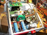
Picture shows present status as per this writing moment.
Cheers, Finn and Daniel
Finn Hammer, Sun Aug 26 2007, 08:13PM
This has been a rewarding weekend.
When Daniel arrived, and I proudly showed him the CCPS, I wanted to show him how long it took to get hot when the variac was turned up full.
I had done this several times, but right this time it went *crack*, and blew a fuse.
Enter rebuild mode. Thanks god those IGBT`s were cheap.
During the tuning procedure we noticed that the transformers were sensitive like a tesla coil.
We took them out and moved the one around next to the one we had sig. gen. and scope on. Found out they influence each other a lot, depending on wether they are in phase or not. These transformers resonate at 80kHz, but could be brought to resonate at from 70 o 100kHz depending on phasing and distance.
This sensitivity would be an argument for using close coupling in the transformer and external choke, which in turn could be adjusted easily.
Rebuilt, the same bridge blew almost instantly.
Decided to use the one good bridge to test how parallel transformers would share current, and they did well.
Today we went searching in the stock and found a couple of FUJI 2MBI300N-120
 With internal current limiting, not suitable for DRSSTC duty but perfect for this job.
We had given up driving the transformers with IGBT`s barely able to handle the current load, and decided to parallell the primarys and use just one heavy bridge.
How to drive those gates?
The UCC37322 chips didn`t handle the task well. We tried to use the one good bridge, only to realise that it will not deliver a 50% duty cycle. So what to do?
I had in my mind the picture from data sheets, of the TTL output from chips, and took a closer look, well right! it is a PN pair with the gates tied together. Woila! the beefy driver!
We lashed one together, and got some gate waveforms that resembled square waves.
Tried to power up the beast, and, well it didn`t get hardly hot at all, so we made this video of a jacops ladder.

We didn`t get any of the fancy voltage probe stuff done, we built 5 bridges and blew 4 but we got there:
We recorded something like 60 primary amps during this shot which is below 2.4kW because we were in a 10A fuse doing it. Sorry, we were too tired to make better measurements, after 2 days of 14 hours each, full time of learning and doing.
So this has been a fun day: Using the tools from the very first SSTC work, the plasmasonic and the beefy driver, we came out to the bleeding edge with a CCPS.
At present gate drive is per beefy driver and gate transformer, we will change that to dedicated drivers before next update.

Picture shows present status as per this writing moment.
Cheers, Finn and Daniel
Re: CCPS (Capacitor Charging Power Supply)
Marko, Mon Aug 27 2007, 12:04AM
Aw, the number of dead IGBT's completely sucks finn.. I'm glad you've got it working now.
Don't you fear that it may just have been overheating what killed them? Really lot of power and small heatsinks. Bricks don't look happy neither! (How did you fix them to heatsinks smaller than their footprint after all? )
)
Regarding transformers interfering, maybe you could put some shielding between/around them and just leave-them-alone?
I'm just thinking how could a self-resonant controller be built for such a thing, and how beneficial would it be. (Waveform shape is weird so, some kind of zero cross detector followed by logic)
The choke of few tens of uH is not a too big problem, few turns on #26 toroid would do for lots of current. Much harder is, as I think to construct a transformer with lower leakage inductance.
Marko, Mon Aug 27 2007, 12:04AM
Aw, the number of dead IGBT's completely sucks finn.. I'm glad you've got it working now.
Don't you fear that it may just have been overheating what killed them? Really lot of power and small heatsinks. Bricks don't look happy neither! (How did you fix them to heatsinks smaller than their footprint after all?
 )
)Regarding transformers interfering, maybe you could put some shielding between/around them and just leave-them-alone?
I'm just thinking how could a self-resonant controller be built for such a thing, and how beneficial would it be. (Waveform shape is weird so, some kind of zero cross detector followed by logic)
The choke of few tens of uH is not a too big problem, few turns on #26 toroid would do for lots of current. Much harder is, as I think to construct a transformer with lower leakage inductance.
Re: CCPS (Capacitor Charging Power Supply)
Finn Hammer, Mon Aug 27 2007, 06:35AM
Current handling ability drops with temperature, so.....
Oh, we were getting mean, so the bricks got fixed with tye wraps
It`s ok as it is now. I just thought I`d mention it. When we had 2 separate bridges and one controller, putting a Pearson near one transformer and altering it`s freq. was a disaster.
Cheers, Finn Hammer
Finn Hammer, Mon Aug 27 2007, 06:35AM
Marko wrote ...
Don't you fear that it may just have been overheating what killed them? Really lot of power and small heatsinks. Bricks don't look happy neither! (How did you fix them to heatsinks smaller than their footprint after all? )
)
Don't you fear that it may just have been overheating what killed them? Really lot of power and small heatsinks. Bricks don't look happy neither! (How did you fix them to heatsinks smaller than their footprint after all?
 )
)Current handling ability drops with temperature, so.....
Oh, we were getting mean, so the bricks got fixed with tye wraps
Marko wrote ...
Regarding transformers interfering, maybe you could put some shielding between/around them and just leave-them-alone?
Regarding transformers interfering, maybe you could put some shielding between/around them and just leave-them-alone?
It`s ok as it is now. I just thought I`d mention it. When we had 2 separate bridges and one controller, putting a Pearson near one transformer and altering it`s freq. was a disaster.
Marko wrote ...
Much harder is, as I think to construct a transformer with lower leakage inductance.
This would be a matter of putting the windings on the same leg, one on top of the other. No problem at all. With the amount of turns per volt, there is no need for more than one layer anyway, so no extra insulation problems. And there would be room for twice the amount of copper.Much harder is, as I think to construct a transformer with lower leakage inductance.
Cheers, Finn Hammer
Re: CCPS (Capacitor Charging Power Supply)
Finn Hammer, Sat Sept 01 2007, 10:03PM
During the week I built this gate driver:
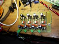
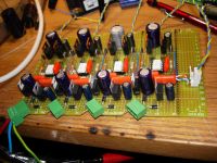
It is so strange that the controll circuitry is getting more complex than the circuit it is controlling.. another view:
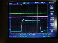
And here is a shot of it driving the gate of a CM600, without gate resistor. It is 50% duty cycle, so it is really a 97.6 kHz pulse...
The gate driver consists of a IRF530 and a IRF 9540 on top.
The gates of these MosFets are driven by an Agilent HCPL-J312 Optocoupler gate driver, which I used only because I could not get the Fairchild FOD 3180. The latter is a fast optocoupler worthy of use in feedback systems, due to a super low 200nS propagation delay.
Well, this does not matter here, I`m oscillator driven.
The opto gets it`s timing impulses from the TL494, buffered by UCC37321 because I had to invert the signals.
There are +24 and -5 volts regulators on board. I wonder how the high side drivers are going to respond to being swung 560 volts, but we`l see. I feel comfort by the fact that there is 50% dead time.
The gates of the 530/9530 pair had to be fed by a 500 ohm resistor, and discharged trough a 1n5819 diode and a 15ohm resistor. the former to avoid the shoot trough current spikes (100nS pulses of 4A) the latter to keep discharge current lower than the gate drivers 2.5A limit.
The IGBT`s have been changed to SEMITRANS SKM 400GB124D because they are easy to drive.
It may seem overkill, to use these bricks, but I have been reading up on this topology, and this paper

gave me a jolt, because it states that with the resonant capacitor size I have available, I`l only be able to transfer around 2kVA.
I`l have to look into that, but In the end, maby we are into a transformer rewind.
I won`t have time to do more work this weekend, but comments are welcome.
Cheers, Finn Hammer
Finn Hammer, Sat Sept 01 2007, 10:03PM
During the week I built this gate driver:

It is so strange that the controll circuitry is getting more complex than the circuit it is controlling.. another view:

And here is a shot of it driving the gate of a CM600, without gate resistor. It is 50% duty cycle, so it is really a 97.6 kHz pulse...

The gate driver consists of a IRF530 and a IRF 9540 on top.
The gates of these MosFets are driven by an Agilent HCPL-J312 Optocoupler gate driver, which I used only because I could not get the Fairchild FOD 3180. The latter is a fast optocoupler worthy of use in feedback systems, due to a super low 200nS propagation delay.
Well, this does not matter here, I`m oscillator driven.
The opto gets it`s timing impulses from the TL494, buffered by UCC37321 because I had to invert the signals.
There are +24 and -5 volts regulators on board. I wonder how the high side drivers are going to respond to being swung 560 volts, but we`l see. I feel comfort by the fact that there is 50% dead time.
The gates of the 530/9530 pair had to be fed by a 500 ohm resistor, and discharged trough a 1n5819 diode and a 15ohm resistor. the former to avoid the shoot trough current spikes (100nS pulses of 4A) the latter to keep discharge current lower than the gate drivers 2.5A limit.
The IGBT`s have been changed to SEMITRANS SKM 400GB124D because they are easy to drive.
It may seem overkill, to use these bricks, but I have been reading up on this topology, and this paper

gave me a jolt, because it states that with the resonant capacitor size I have available, I`l only be able to transfer around 2kVA.
I`l have to look into that, but In the end, maby we are into a transformer rewind.
I won`t have time to do more work this weekend, but comments are welcome.
Cheers, Finn Hammer
Re: CCPS (Capacitor Charging Power Supply)
Daniel Uhrenholt, Sun Sept 02 2007, 12:56AM
Hi Finn.
I think it’s time for me to say a few things about our project .
I like your gate driver, and after an afternoon in your workshop this weekend, with blown optocouplers and a headache, I am pretty satisfied with the results. Too bad we didn’t get a chance to test it on our CCPS…
About the transformer, I must agree with you!
I think we should do it the “Ward†way, and place the primary under the secondary winding, and make an extra series inductor to adjust from. If you agree with me I’ll order two of these from RS (Part number) 213-4470, and use the cores we have in parallel.
We need more space in our HP214A cabinet
Cheers Daniel.
Daniel Uhrenholt, Sun Sept 02 2007, 12:56AM
Hi Finn.
I think it’s time for me to say a few things about our project .
I like your gate driver, and after an afternoon in your workshop this weekend, with blown optocouplers and a headache, I am pretty satisfied with the results. Too bad we didn’t get a chance to test it on our CCPS…
About the transformer, I must agree with you!
I think we should do it the “Ward†way, and place the primary under the secondary winding, and make an extra series inductor to adjust from. If you agree with me I’ll order two of these from RS (Part number) 213-4470, and use the cores we have in parallel.
We need more space in our HP214A cabinet

Cheers Daniel.
Re: CCPS (Capacitor Charging Power Supply)
Steve Conner, Sun Sept 02 2007, 10:40AM
Yay, this is looking great
About the matching inductor, I think Steve used an air cored one. You don't need very much inductance if you're transferring a lot of power, as you figured out. If you use ferrite, you'll need a large air gap to avoid saturation. You certainly wouldn't want to use that RS part you mentioned without any airgap!
Steve Conner, Sun Sept 02 2007, 10:40AM
Yay, this is looking great

About the matching inductor, I think Steve used an air cored one. You don't need very much inductance if you're transferring a lot of power, as you figured out. If you use ferrite, you'll need a large air gap to avoid saturation. You certainly wouldn't want to use that RS part you mentioned without any airgap!

Re: CCPS (Capacitor Charging Power Supply)
Marko, Sun Sept 02 2007, 10:59AM
Hi Steve, Daniel, Finn
You need Only few tens of uH at most, and I think material #26 (yellow-white toroids) would be more than fine for you at these currents.
With rough calculation I think even the size from PC power supply would suffice.
Steve, I don't think airgap actually does any good with inductors like these.
Inductance will reduce proportionally with permeability and we really get nothing except need to wind more copper onto the core. (OK, with rod cores, this may save some ferrite from other side).
Material #26 has saturation B of about afaik 1T while #77 ferrite is 0.45T max according to CWS table. Most use ferrite to maybe 0.3T.
In any wa ferrite core would need to be larger and more expensive for this application.
The great thing about air cored coil is it's absolute stability, but it is a bad thing when we need 15amps continuously through it at 50kHz.
Marko, Sun Sept 02 2007, 10:59AM
Hi Steve, Daniel, Finn
You need Only few tens of uH at most, and I think material #26 (yellow-white toroids) would be more than fine for you at these currents.
With rough calculation I think even the size from PC power supply would suffice.
About the matching inductor, I think Steve used an air cored one. You don't need very much inductance if you're transferring a lot of power, as you figured out. If you use ferrite, you'll need a large air gap to avoid saturation. You certainly wouldn't want to use that RS part you mentioned without any airgap!
Steve, I don't think airgap actually does any good with inductors like these.
Inductance will reduce proportionally with permeability and we really get nothing except need to wind more copper onto the core. (OK, with rod cores, this may save some ferrite from other side).
Material #26 has saturation B of about afaik 1T while #77 ferrite is 0.45T max according to CWS table. Most use ferrite to maybe 0.3T.
In any wa ferrite core would need to be larger and more expensive for this application.
The great thing about air cored coil is it's absolute stability, but it is a bad thing when we need 15amps continuously through it at 50kHz.
Re: CCPS (Capacitor Charging Power Supply)
Daniel Uhrenholt, Sun Sept 02 2007, 11:56AM
Hi Steve and Marko
I did some calculations today on how many Amps we need on the primary to get about 15kVA, and it looks like we need a major rebuild of the supply
I think we have to get a Fo about 50kHz and a C about 1uF
So if P= F*E
E=0.5*560 2* 0.000002 = 0.3136J
P= 50000Hz*0.3136J =15680W
And with a L of 5.07uH we get 248Amps on the primary… That’s a lot of heat we need to get rid off!!
Well I will buy the cores anyway, I want to build a smaller but powerful CCPS when we are done with this coil.
Cheers, Daniel
Daniel Uhrenholt, Sun Sept 02 2007, 11:56AM
Hi Steve and Marko
I did some calculations today on how many Amps we need on the primary to get about 15kVA, and it looks like we need a major rebuild of the supply

I think we have to get a Fo about 50kHz and a C about 1uF
So if P= F*E
E=0.5*560 2* 0.000002 = 0.3136J
P= 50000Hz*0.3136J =15680W
And with a L of 5.07uH we get 248Amps on the primary… That’s a lot of heat we need to get rid off!!
Well I will buy the cores anyway, I want to build a smaller but powerful CCPS when we are done with this coil.
Cheers, Daniel
Re: CCPS (Capacitor Charging Power Supply)
Steve Conner, Sun Sept 02 2007, 12:15PM
Are you sure about that? The peak current in the resonant circuit should only be something like 3 times what it would be in a hard-switched converter. That gives a loaded Q of 3 even at full output voltage.
For 15kW on a 560V DC bus, a hard-switched converter would run about 30A, so you should have something like 90A peak current. Say 100 since you have an IGBT brick handy
Try designing your circuit such that the leakage inductance and capacitor end up with a surge impedance of (560/100) ohms and a resonant frequency of say 100kHz, or whatever frequency you decide gives acceptable losses. (Switching losses should be low because you have zero current at turn-on and turn-off, so you might be able to aim higher in frequency than the IGBT datasheet would suggest. However, you have to bear in mind that if the loaded Q is too low, you will lose your zero-current turn-off at higher output voltages. This is a trade-off.)
Steve Conner, Sun Sept 02 2007, 12:15PM
Are you sure about that?
 The peak current in the resonant circuit should only be something like 3 times what it would be in a hard-switched converter. That gives a loaded Q of 3 even at full output voltage.
 For 15kW on a 560V DC bus, a hard-switched converter would run about 30A, so you should have something like 90A peak current. Say 100 since you have an IGBT brick handy

Try designing your circuit such that the leakage inductance and capacitor end up with a surge impedance of (560/100) ohms and a resonant frequency of say 100kHz, or whatever frequency you decide gives acceptable losses. (Switching losses should be low because you have zero current at turn-on and turn-off, so you might be able to aim higher in frequency than the IGBT datasheet would suggest. However, you have to bear in mind that if the loaded Q is too low, you will lose your zero-current turn-off at higher output voltages. This is a trade-off.)
Re: CCPS (Capacitor Charging Power Supply)
Daniel Uhrenholt, Sun Sept 02 2007, 12:49PM
Hi Steve,
I’m almost sure that my calculations are correct… The I peak of 248A is in the resonance circuit, and looking at other peoples work with high power CCPS`s, their I peak resonant current is in the 100-1100A area..
 1120 Amps for their 42kW supply
 152A for their 32kHz 15kW supply.
Cheers, Daniel
Daniel Uhrenholt, Sun Sept 02 2007, 12:49PM
Hi Steve,
I’m almost sure that my calculations are correct… The I peak of 248A is in the resonance circuit, and looking at other peoples work with high power CCPS`s, their I peak resonant current is in the 100-1100A area..
 1120 Amps for their 42kW supply
 152A for their 32kHz 15kW supply.
Cheers, Daniel
Re: CCPS (Capacitor Charging Power Supply)
Marko, Sun Sept 02 2007, 12:55PM
Right now he has impedance of 2,23 ohms which is quite way far. As far as I understood it, he's limited by total charge he can push through the cap in one cycle, and making the cap big enough makes characteristic Z way too low. If I understood anything of this?
Steve: You didn't answer the thing about cores.. I actually wonder if I'm right or wrong
Marko, Sun Sept 02 2007, 12:55PM
For 15kW on a 560V DC bus, a hard-switched converter would run about 30A, so you should have something like 90A peak current. Say 100 since you have an IGBT brick handy
Right now he has impedance of 2,23 ohms which is quite way far. As far as I understood it, he's limited by total charge he can push through the cap in one cycle, and making the cap big enough makes characteristic Z way too low. If I understood anything of this?
Steve: You didn't answer the thing about cores.. I actually wonder if I'm right or wrong

Re: CCPS (Capacitor Charging Power Supply)
Steve Conner, Sun Sept 02 2007, 04:09PM
Re the thing about cores, it's a known fact that the energy storage before saturation is proportional to the size of the airgap. An ungapped ferrite core can store practically no energy. I've not investigated it myself, but I hear that gapped ferrite isn't nearly so good as iron powder toroids.
Daniel: It always seemed to me that the CCPS tank circuit impedance was a tradeoff between conduction losses caused by higher peak currents, and switching losses caused by it falling out of ZCS at certain output voltages due to not having enough peak current. I think Marco Denicolai explored this with PSpice in a lot of detail. Running at a lower frequency than f0/2 might help too.
Re: CCPS (Capacitor Charging Power Supply)
Finn Hammer, Sun Sept 02 2007, 05:13PM
Thanks for the input,
These numbers are for a single transformer, topping out at 4kV.
At present:
Z= 25.44, 92kHz
68nF, 44uH, Ipeak, start 25A Ipeak, end 50A , 4kW (1uF to 4kV, 8J, in 2mS)
So we we missed the goal by 50%.....
With a Z of 5, 100kHz,
315nF, 8.04uH, Ipeak, start 100A Ipeak, end 200A (1uF to 4kV, 8J, in 0.4mS = 20kW)
Yes, I get the picture.
The transformer probably has to leave the cabinet, and sure is up for a rewind. The winding window will get *optimally filled* by pie shaped secondary windings.
Waw, this sure is fun stuff.
I feel kind of tempted to skip the negative gate drive on the IGBT`s and adopt Terry`s source follower supplies, from his DRSSTC, but that may have to wait untill the next iteration.
Cheers, Finn Hammer
Finn Hammer, Sun Sept 02 2007, 05:13PM
Thanks for the input,
These numbers are for a single transformer, topping out at 4kV.
At present:
Z= 25.44, 92kHz
68nF, 44uH, Ipeak, start 25A Ipeak, end 50A , 4kW (1uF to 4kV, 8J, in 2mS)
So we we missed the goal by 50%.....
With a Z of 5, 100kHz,
315nF, 8.04uH, Ipeak, start 100A Ipeak, end 200A (1uF to 4kV, 8J, in 0.4mS = 20kW)
Yes, I get the picture.
The transformer probably has to leave the cabinet, and sure is up for a rewind. The winding window will get *optimally filled* by pie shaped secondary windings.

Waw, this sure is fun stuff.
I feel kind of tempted to skip the negative gate drive on the IGBT`s and adopt Terry`s source follower supplies, from his DRSSTC, but that may have to wait untill the next iteration.
Cheers, Finn Hammer
Re: CCPS (Capacitor Charging Power Supply)
Daniel Uhrenholt, Sun Sept 02 2007, 07:51PM
Finn,
It looks great, I can’t wait to make an 20kW transformer
Cheers, Daniel
Daniel Uhrenholt, Sun Sept 02 2007, 07:51PM
Finn,
It looks great, I can’t wait to make an 20kW transformer
Cheers, Daniel
Re: CCPS (Capacitor Charging Power Supply)
Finn Hammer, Sun Sept 02 2007, 08:03PM
All,
Daniel and I have a problem understanding the relationship btwn. frequency and power transfer in the CCPS:
In this paper:

and this:

Well, same authors!
The transfer of energy is calculated as:
P = Fres * 0,5 * C * (2V)^2
4 times the energy stored in the resonant cap, per cycle.
Can anyone explain why it is 4 times the energy stored in the cap, and not just one times the energy stored in that cap?
We know it is true, because it is consistent with Microsim simulations.
Cheers Finn Hammer
Finn Hammer, Sun Sept 02 2007, 08:03PM
All,
Daniel and I have a problem understanding the relationship btwn. frequency and power transfer in the CCPS:
In this paper:

and this:

Well, same authors!
The transfer of energy is calculated as:
P = Fres * 0,5 * C * (2V)^2
4 times the energy stored in the resonant cap, per cycle.
Can anyone explain why it is 4 times the energy stored in the cap, and not just one times the energy stored in that cap?
We know it is true, because it is consistent with Microsim simulations.
Cheers Finn Hammer
Re: CCPS (Capacitor Charging Power Supply)
Finn Hammer, Wed Sept 05 2007, 07:38PM
Insight is slowly trickling in, and I now realise, that it was probably wrong to assume up to 2kW into the jacobs ladder we made the other weekend.
Point is, the supply delivers constant _current_ into a load, so if this load is a low resistance, which I think a Jacobs ladder arc is, then the current is delivered into a low potential, and therefore the delivered power is also low.
Anyone know the resistance of a jacob ladder arc?
This weekend, we would like to test the supply under power, and we would like to do so into a resistive load.
Since we are expecting something in the vicinity of 15-20kW a water resitor comes to mind. A big barrell with salt water and copper electrodes would allow power measurements to be done with temperature rise as the calibration.
But which resistance will mirror the condition of the supply topping up, into a capacitor with 8kV on it?
Able to deliver 4 amps into the load, at a maximum voltage of 8kV, my shot at it is, that the resistor must be not over R=E/I 8000/4=2k. A little lower, really, to keep the load from rising to a voltage over the reach of the supply.
Does this sound reasonable?
Cheers, Finn Hammer
Re: CCPS (Capacitor Charging Power Supply)
Hazmatt_(The Underdog), Wed Sept 05 2007, 07:45PM
Take some time to do a short circuit and open circuit test on the transformer, then go to the 4hv wiki under electronics and do the transformer analysis. That will give you the extracted elements of the transformer so you can model your problem.
You can find the impedance of the arc from the reflected load on the transformer. Essentially its short circuit at this point so you need to know the equivalent series secondary resistance at this point, but the transformer calculations will help with that.
Re: CCPS (Capacitor Charging Power Supply)
Steve Ward, Wed Sept 05 2007, 08:52PM
Finn, i think your 2k ohm load is the correct value (or at least pretty close) for doing a high power measurement. Keep in mind that this is more stressful than charging a cap, since when you charge a cap the average output power is 1/2 the peak output power when topping off the cap.
As to the jacobs ladder, why not just measure the voltage across the arc? I think it was in the few kV range for me (maybe 2kV).
Re: CCPS (Capacitor Charging Power Supply)
Steve Conner, Wed Sept 05 2007, 10:44PM
I always wondered about the resistance of a Jacobs ladder. The maximum power transfer theorem says that you should be able to stretch an arc until it's pulling as much power as your supply can give. When it hits the maximum power point, it becomes unstable and goes out. That's what I believe anyway.
Re: CCPS (Capacitor Charging Power Supply)
Steve Ward, Thu Sept 06 2007, 03:38AM
Steve,
That is what i have measured in the past, but the voltage required to sustain longer growing sparks seems to go up with the square of the arc length (this is purely "by eye" type of measurement). In anycase, the voltage drop across the arc climbs steeply just before it breaks. It may present a load thats not too far off from charging a cap.
Re: CCPS (Capacitor Charging Power Supply)
Daniel Uhrenholt, Thu Sept 06 2007, 02:31PM
Hi Finn.
I have to admit that I think a Jacobs’s ladder is the way to go with our measurements at the moment.
But let’s see what weekend brings…
After some hard days with a lot of overtime at my place of
work, I managed to calculate a bit more on how many Jules/sec we can deliver with our CCPS as it is now.
Last time we had a Jacob’s ladder on the supply, we had 400Vdc on the bridge. And with the transformers in parallel, we has 136nF in the tank and a Fo about 92kHz.
That gives about 4000 J/sec, but if we get the supply on three phase and 560Vdc in the bridge, we should get up to 7800 J/sec… That’s almost twice the energy!!!
We need more C or a higher Fo
I can’t prove that my calculations are correct, because my differential probe and my other probes are at your place
Cheers, Daniel
Daniel Uhrenholt, Thu Sept 06 2007, 02:31PM
Hi Finn.
I have to admit that I think a Jacobs’s ladder is the way to go with our measurements at the moment.
But let’s see what weekend brings…
After some hard days with a lot of overtime at my place of
work, I managed to calculate a bit more on how many Jules/sec we can deliver with our CCPS as it is now.
Last time we had a Jacob’s ladder on the supply, we had 400Vdc on the bridge. And with the transformers in parallel, we has 136nF in the tank and a Fo about 92kHz.
That gives about 4000 J/sec, but if we get the supply on three phase and 560Vdc in the bridge, we should get up to 7800 J/sec… That’s almost twice the energy!!!
We need more C or a higher Fo

I can’t prove that my calculations are correct, because my differential probe and my other probes are at your place

Cheers, Daniel
Re: CCPS (Capacitor Charging Power Supply)
Finn Hammer, Sat Sept 08 2007, 08:00PM
All,
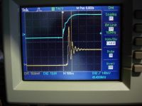
Today, scoping across the IGBT`s suggested that we`d probably better make us a low inductance bus:
Not that it solved our problems, because the whole thing still rings like the liberty bell:
TEK TDS2014, Metratek MX9003 diff probe, stock probe on low side gate.
(Yellow trace is voltage across a low side IGBT, blue is gate.)
We read up on RCD snubbers, and placed 1 across the buss between the lytics and the first IGBT.
The snubber consists of a 150nF CD942 cap, an IXYS DSEI 60-06A fast diode and a 1.5ohms resistor.
This brought os to this situation:
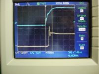
We then placed 2 more snubbers on the bus:
(The one to the left is the midle one, the 3rd is off the picture to the left.)
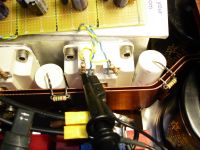
This resulted in this ringing waveform:
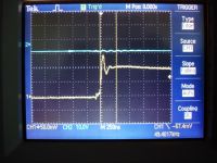
These shots are at really low voltages, we forgot to record the voltage, but below 50V.
When we turn the voltage up higher, the overshoot begins to climb up to over 50%, which is worrying, because it will correspond to more than 900V at 560V on the bus.
What?s left to do? Transorbs? Can we calculate the power in these overshots, so that we can also get an idea of how many tranzorbs we need?
Cheers, Finn & Daniel
Finn Hammer, Sat Sept 08 2007, 08:00PM
All,
Today, scoping across the IGBT`s suggested that we`d probably better make us a low inductance bus:

Not that it solved our problems, because the whole thing still rings like the liberty bell:
TEK TDS2014, Metratek MX9003 diff probe, stock probe on low side gate.
(Yellow trace is voltage across a low side IGBT, blue is gate.)

We read up on RCD snubbers, and placed 1 across the buss between the lytics and the first IGBT.
The snubber consists of a 150nF CD942 cap, an IXYS DSEI 60-06A fast diode and a 1.5ohms resistor.
This brought os to this situation:

We then placed 2 more snubbers on the bus:
(The one to the left is the midle one, the 3rd is off the picture to the left.)

This resulted in this ringing waveform:

These shots are at really low voltages, we forgot to record the voltage, but below 50V.
When we turn the voltage up higher, the overshoot begins to climb up to over 50%, which is worrying, because it will correspond to more than 900V at 560V on the bus.
What?s left to do? Transorbs? Can we calculate the power in these overshots, so that we can also get an idea of how many tranzorbs we need?
Cheers, Finn & Daniel
Re: CCPS (Capacitor Charging Power Supply)
Finn Hammer, Sun Sept 09 2007, 09:11AM
All,
If you will all have me excused for double posting, but I think everybody interested in H-bridge design should see this.
As you all know, the gate waveform is regularly displayed with great pride, "the squarer the better" seems to be the rule of the day.
But what about the voltage across swiching devices? We have just seen what ringing it can lead to.
Here are the waveforms showing Current in green, Voltage in blue and gate waveform (yellow), with a 22ohm gate resistor
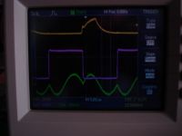
Nice and calm, and the gate driver is happy, gate resistor is hot (2W) even the main IGBT`s are swallower.
Here is a shot at 250nS to show the calm voltage frontedge at 150V bus,
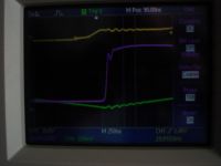
So with the new gate resistors in situ, the low inductance buss and the snubbers really came to play in harmony.
Looks like we are ready to ramp the voltage up to max, now.
Not today, though. There is an open house arrangement at the regional electricity plant, won`t miss that!
Cheers, Finn & Daniel
Finn Hammer, Sun Sept 09 2007, 09:11AM
All,
If you will all have me excused for double posting, but I think everybody interested in H-bridge design should see this.
As you all know, the gate waveform is regularly displayed with great pride, "the squarer the better" seems to be the rule of the day.
But what about the voltage across swiching devices? We have just seen what ringing it can lead to.
Here are the waveforms showing Current in green, Voltage in blue and gate waveform (yellow), with a 22ohm gate resistor

Nice and calm, and the gate driver is happy, gate resistor is hot (2W) even the main IGBT`s are swallower.
Here is a shot at 250nS to show the calm voltage frontedge at 150V bus,

So with the new gate resistors in situ, the low inductance buss and the snubbers really came to play in harmony.
Looks like we are ready to ramp the voltage up to max, now.
Not today, though. There is an open house arrangement at the regional electricity plant, won`t miss that!
Cheers, Finn & Daniel
Re: CCPS (Capacitor Charging Power Supply)
Steve Conner, Sun Sept 09 2007, 10:20AM
Hi Finn & Daniel,
As far as I know, you are right. The answer to gate drive is not always "As fast as you can". You have to experiment to find out what is right for your system. I have built some (much smaller) DC-DC converters, and I spent a day fiddling with gate resistors and resistor-diode networks until I found the values that made the MOSFETs run coolest.
I'm also playing with those white Semikron IGBTs, and I've also noticed some fairly serious ringing on the bus even at low DC bus voltages. Maybe they are really fast

Re: CCPS (Capacitor Charging Power Supply)
Marko, Sun Sept 09 2007, 11:17AM
Some awesome copper work over here, and really admirable low-inductance design.
Regarding supply transients, I don't believe they've ever caused that much trouble as you guys believe.
You should be able to absorb them with TVS's and judge the dissipation from them; I don't think it will be a lot.
Regarding Jacob's ladders.. do you guys draw arcs directly from the transformer (no doubler, filter)? How do you keep ZCS then? I mean, spark behavior is quite chaotic.
Re: CCPS (Capacitor Charging Power Supply)
Finn Hammer, Sun Sept 09 2007, 12:33PM
This way, we don`t have to snub at all.
Yes, we drive them directly.
ZCS is acheived by design. It is inherent in the series resonant topology.

I hope you will show the combination of gate waveform and voltage waveform that you end up with.
Cheers, Finn Hammer
Finn Hammer, Sun Sept 09 2007, 12:33PM
Marko wrote ...
Some awesome copper work over here, and really admirable low-inductance design.
Thanks! As you maby know, we are both toolmakers, so the metal work comes easy.Some awesome copper work over here, and really admirable low-inductance design.
Marko wrote ...
Regarding supply transients, I don't believe they've ever caused that much trouble as you guys believe.
The mosfets and the IGBT`s can avalance those spikes, at the expence of heat. I think the first bridge that blew, did so, trying to snub some really nasty spikes, by avalancing, which at that time were lower frequency, meaning that they were wider and more powerfull.Regarding supply transients, I don't believe they've ever caused that much trouble as you guys believe.
Marko wrote ...
You should be able to absorb them with TVS's and judge the dissipation from them; I don't think it will be a lot.
No doubt that would be possible, but only to some extent. From what we have seen, a TVS can only snub a 100% ringing down to 50%.You should be able to absorb them with TVS's and judge the dissipation from them; I don't think it will be a lot.
This way, we don`t have to snub at all.
Marko wrote ...
Regarding Jacob's ladders.. do you guys draw arcs directly from the transformer (no doubler, filter)? How do you keep ZCS then? I mean, spark behavior is quite chaotic.
Regarding Jacob's ladders.. do you guys draw arcs directly from the transformer (no doubler, filter)? How do you keep ZCS then? I mean, spark behavior is quite chaotic.
Yes, we drive them directly.
ZCS is acheived by design. It is inherent in the series resonant topology.
Steve Conner wrote ...
Hi Finn & Daniel,
I'm also playing with those white Semikron IGBTs, and I've also noticed some fairly serious ringing on the bus even at low DC bus voltages. Maybe they are really fast
I think they are very fast Hi Finn & Daniel,
I'm also playing with those white Semikron IGBTs, and I've also noticed some fairly serious ringing on the bus even at low DC bus voltages. Maybe they are really fast


I hope you will show the combination of gate waveform and voltage waveform that you end up with.
Cheers, Finn Hammer
Re: CCPS (Capacitor Charging Power Supply)
Marko, Sun Sept 09 2007, 12:46PM
From all I learned by now the supply ZCS's only into a capacitive load.
With resistive load the resonant frequency of the primary circuit is always going to be lower than this (I can be like 100% sure from my observations) and heavily dependent on load/arc size.
Marko, Sun Sept 09 2007, 12:46PM
Yes, we drive them directly.
ZCS is acheived by design. It is inherent in the series resonant topology.
From all I learned by now the supply ZCS's only into a capacitive load.
With resistive load the resonant frequency of the primary circuit is always going to be lower than this (I can be like 100% sure from my observations) and heavily dependent on load/arc size.
Re: CCPS (Capacitor Charging Power Supply)
Finn Hammer, Sun Sept 09 2007, 03:50PM
Cheers, Finn Hammer
Finn Hammer, Sun Sept 09 2007, 03:50PM
Marko wrote ...
From all I learned by now the supply ZCS's only into a capacitive load.
With resistive load the resonant frequency of the primary circuit is always going to be lower than this (I can be like 100% sure from my observations) and heavily dependent on load/arc size.
You have been into this before. Could you please describe in detail, (Schematic, pictures, spice file, scope shots) what circuit you made these observations in?From all I learned by now the supply ZCS's only into a capacitive load.
With resistive load the resonant frequency of the primary circuit is always going to be lower than this (I can be like 100% sure from my observations) and heavily dependent on load/arc size.
Cheers, Finn Hammer
Re: CCPS (Capacitor Charging Power Supply)
Steve Conner, Sun Sept 09 2007, 03:55PM
Finn, I forgot to ask, what Semikron IGBT bricks are you using? Mine are the SKM300GB123D.
Steve Conner, Sun Sept 09 2007, 03:55PM
Finn, I forgot to ask, what Semikron IGBT bricks are you using? Mine are the SKM300GB123D.
Re: CCPS (Capacitor Charging Power Supply)
Finn Hammer, Sun Sept 09 2007, 05:46PM
Steve,
They are SKM 400GB124D
Pretty cool bricks.
Chers, Finn Hammer
Finn Hammer, Sun Sept 09 2007, 05:46PM
Steve Conner wrote ...
Finn, I forgot to ask, what Semikron IGBT bricks are you using? Mine are the SKM300GB123D.
Finn, I forgot to ask, what Semikron IGBT bricks are you using? Mine are the SKM300GB123D.
Steve,
They are SKM 400GB124D
Pretty cool bricks.
Chers, Finn Hammer
Re: CCPS (Capacitor Charging Power Supply)
Steve Ward, Mon Sept 10 2007, 02:25AM
Finn,
While the slow switching of the gate might give pretty square waves it comes at the cost of increased switching loss. Luckily you can finely tune the thing to get pretty good ZCS.
I think the 50% overshoot you see is in fact very common when using these brick sized IGBTs. The reason being is that they have a pretty large internal inductance (relatively speaking when compared with a TO-247). And as you have found, using a snubber does help, but you still have something like 20-30nH snubber L and another 20-30nH (for newer bricks) or 50-100nH (for older ones like the CM300's i use) of IGBT inductance. I believe it is due to this that most brick datasheets give their example ratings with only 600V applied to 1200V devices (because the overshoot will almost always be large).
So as Conner said, you really should be tuning your gate R for best device efficiency and not just for looks (im adding that second part).
Re: CCPS (Capacitor Charging Power Supply)
Steve Conner, Mon Sept 10 2007, 08:49AM
Well, if the stray inductance were mostly inside the brick, the ringing waveform should be bigger on the output terminal than on the DC bus terminals. Does that match up with what you saw, Finn?
As far as the seriousness of spikes goes, I believe that as long as the energy stored in the stray inductance (0.5*L*I^2) is small compared to the IGBT's avalanche rating, and the power dissipated through avalanching is small compared to the device's rated dissipation, it should be OK. Of course, for devices with no avalanche rating all bets are off! :(
I think the 124 series are faster still than the 123.

Re: CCPS (Capacitor Charging Power Supply)
Marko, Mon Sept 10 2007, 12:57PM
Yes, but I'm rather going to open another thread than hijack this up.
My ''observations'' involve royer converters and are about what I thought to be 'basic transformer theory'. And described behavior of your CCPS is 'odd' from that point of view.
My idea of it was consistent with Steve's explanation so I thought I'm OK.
I never built anything like CCPS and can't by any way claim I have a clue what I'm talking about :(
Marko, Mon Sept 10 2007, 12:57PM
You have been into this before. Could you please describe in detail, (Schematic, pictures, spice file, scope shots) what circuit you made these observations in?
Yes, but I'm rather going to open another thread than hijack this up.
My ''observations'' involve royer converters and are about what I thought to be 'basic transformer theory'. And described behavior of your CCPS is 'odd' from that point of view.
My idea of it was consistent with Steve's explanation so I thought I'm OK.
I never built anything like CCPS and can't by any way claim I have a clue what I'm talking about :(
Re: CCPS (Capacitor Charging Power Supply)
Finn Hammer, Mon Sept 10 2007, 06:49PM
Yes, I do beleive there was more ringing on the output terminals, but I am not sure, and right now the ringing is back bad, snubbers are frying the resistors and everything is sort of "hot". Have some debugging to do before i can answer that with scopeshots.
Semikron don`t mention the word avalanche in their datasheets.
They say "Non punch through" though, with a little imagination that could be read as an avalanche ability.
Anyone have an opinion about that?
Cheers, Finn Hammer
Finn Hammer, Mon Sept 10 2007, 06:49PM
Steve Conner wrote ...
Well, if the stray inductance were mostly inside the brick, the ringing waveform should be bigger on the output terminal than on the DC bus terminals. Does that match up with what you saw, Finn?
Of course, for devices with no avalanche rating all bets are off! :(
Well, if the stray inductance were mostly inside the brick, the ringing waveform should be bigger on the output terminal than on the DC bus terminals. Does that match up with what you saw, Finn?
Of course, for devices with no avalanche rating all bets are off! :(
Yes, I do beleive there was more ringing on the output terminals, but I am not sure, and right now the ringing is back bad, snubbers are frying the resistors and everything is sort of "hot". Have some debugging to do before i can answer that with scopeshots.
Semikron don`t mention the word avalanche in their datasheets.
They say "Non punch through" though, with a little imagination that could be read as an avalanche ability.
Anyone have an opinion about that?
Cheers, Finn Hammer
Re: CCPS (Capacitor Charging Power Supply)
Sulaiman, Mon Sept 10 2007, 10:34PM
'Punch through" is when both devices in a half-bridge (or one half of a full-bridge) turn on together (briefly)
during switching.
The resulting high current surge usually 'punches through' silicon.
i.e. they have a very high peak current rating, limited by Rds(on) increasing with Ids.
From memory only. (i.e. If it's important, you'd better check my interpretation)
Re: CCPS (Capacitor Charging Power Supply)
Steve Ward, Mon Sept 10 2007, 11:37PM
You are thinking of shoot-through Sulaiman.
Punch-through has to do with the semiconductor material itself and how wide the depletion region becomes (as in, does it exceed the junction width) when the device is saturated. It has really nothing to do with voltage stand off and avalanching (well, at least not directly). I think that PT devices have faster turn off due to an extra layer of highly doped Si to help recombine carriers when Vgs drops below Vth. NPT devices are typically more rugged, but also suffer from greater "tail" currents. From what general knowledge i have of semiconductor physics, this doesnt play much roll with avalanche ratings. Of course, i dont know much about how they make newer IGBTs handle avalanching better than the older types.
Re: CCPS (Capacitor Charging Power Supply)
Sulaiman, Tue Sept 11 2007, 12:24AM
OOPS !
Thanks for the correction.
In penance I just went to the semikron website and did a bit of reading;
Apparently the punch-through effect is deliberately employed!
There are Punch-Through igbts 'PT-IGBT'
and non punch through igbts 'NPT-IGBT'
and the first igbts were designed on the PT-IGBT concept.
I assumed that non punch through igbt was a good thing! doh!
Sulaiman, Tue Sept 11 2007, 12:24AM
OOPS !
Thanks for the correction.
In penance I just went to the semikron website and did a bit of reading;
Apparently the punch-through effect is deliberately employed!
There are Punch-Through igbts 'PT-IGBT'
and non punch through igbts 'NPT-IGBT'
and the first igbts were designed on the PT-IGBT concept.

I assumed that non punch through igbt was a good thing! doh!
Re: CCPS (Capacitor Charging Power Supply)
Finn Hammer, Tue Sept 11 2007, 08:17PM
If it took you a day, I`l be satisfied if I dial it in, in a week!
Right now 22ohm gate resistors run hot, the snubbers last, and the IGBT`s get very hot.
If I remove the gate resistors, the snubbers evaporate instantly, well almost
If I fit 10 ohms gate resistors the snubbers get extremely hot, and the IGBT`s sort of coast along.
I have ordered some 20W non inductive resistors, for the snubbers, and the gates, hope they will last.
What I don`t undestand is why I need snubbers in the first place since there is no current running to interrupt.
CW power electronics, even if it is only 50% dutycycle, is a new challenging world.
Cheers, Finn Hammer
Finn Hammer, Tue Sept 11 2007, 08:17PM
Steve Conner wrote ...
Hi Finn & Daniel,
I have built some (much smaller) DC-DC converters, and I spent a day fiddling with gate resistors and resistor-diode networks until I found the values that made the MOSFETs run coolest.
Hi Finn & Daniel,
I have built some (much smaller) DC-DC converters, and I spent a day fiddling with gate resistors and resistor-diode networks until I found the values that made the MOSFETs run coolest.
If it took you a day, I`l be satisfied if I dial it in, in a week!
Right now 22ohm gate resistors run hot, the snubbers last, and the IGBT`s get very hot.
If I remove the gate resistors, the snubbers evaporate instantly, well almost

If I fit 10 ohms gate resistors the snubbers get extremely hot, and the IGBT`s sort of coast along.
I have ordered some 20W non inductive resistors, for the snubbers, and the gates, hope they will last.
What I don`t undestand is why I need snubbers in the first place since there is no current running to interrupt.
CW power electronics, even if it is only 50% dutycycle, is a new challenging world.
Cheers, Finn Hammer
Re: CCPS (Capacitor Charging Power Supply)
Steve Ward, Wed Sept 12 2007, 06:12PM
Finn, why are you using snubbers? They are 1200V IGBTs running at 650VDC right? Also, what type of snubber are you using? There are 2 ways of doing RCD snubbers, one method discharges the C completely (or nearly) on every cycle while the other discharges it only to "Vcc" on every cycle. Obviously the difference in resistor dissipation can be large. You want to go with the latter, which requires a slightly odd wiring scheme.
Re: CCPS (Capacitor Charging Power Supply)
Finn Hammer, Wed Sept 12 2007, 08:03PM
Steve,
When we started to ramp up the voltage, we noticed bad overshoot, more than 100%, oscillating at 5.8mHz. As you can see on these scopeshots, where green is primary current @ 10A/div, pink is Vbuss @100V/Div.
Notice that current is nicely zero at the voltage step.
]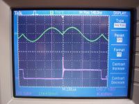
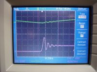
1200V IGBT`s on a 560V bus would be overvolted at full buss voltage.
That`s why, I am against turning up the voltage against odds. And by that I mean that I have no information about avalanche rating on the bricks that I use: Semikron SKM 400GB124D

I know that 600V TVS`es might just cut it, and I have ordered 50 of them for a 3*3 array of 200V types across each IGBT. I`l try that out tomorrow when they arrive.
Untill then, I have been experimenting with the type of RCD snubber that has the resistor across the diode: the type that discharges down to Vbuss.
I register rather wild currents through the diode,
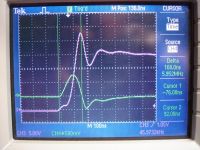
In this shot, pink is buss voltage @ 10V/Div, green is current trough snubber diode @10A/Div.
This translates into 225A through snubber diode at 600Vbuss.
Undershoot of curve corresponds to Trr 35 uS of the diode: IXYS DSEI 60-06A

It should be able to handle it, with heatsinks.
But the question remains: why do I get such spikes when I am not interrupting any current.
Cheers, Finn Hammer
Finn Hammer, Wed Sept 12 2007, 08:03PM
Steve Ward wrote ...
Finn, why are you using snubbers? They are 1200V IGBTs running at 650VDC right? Also, what type of snubber are you using? There are 2 ways of doing RCD snubbers, one method discharges the C completely (or nearly) on every cycle while the other discharges it only to "Vcc" on every cycle. Obviously the difference in resistor dissipation can be large. You want to go with the latter, which requires a slightly odd wiring scheme.
Finn, why are you using snubbers? They are 1200V IGBTs running at 650VDC right? Also, what type of snubber are you using? There are 2 ways of doing RCD snubbers, one method discharges the C completely (or nearly) on every cycle while the other discharges it only to "Vcc" on every cycle. Obviously the difference in resistor dissipation can be large. You want to go with the latter, which requires a slightly odd wiring scheme.
Steve,
When we started to ramp up the voltage, we noticed bad overshoot, more than 100%, oscillating at 5.8mHz. As you can see on these scopeshots, where green is primary current @ 10A/div, pink is Vbuss @100V/Div.
Notice that current is nicely zero at the voltage step.
]


1200V IGBT`s on a 560V bus would be overvolted at full buss voltage.
That`s why, I am against turning up the voltage against odds. And by that I mean that I have no information about avalanche rating on the bricks that I use: Semikron SKM 400GB124D

I know that 600V TVS`es might just cut it, and I have ordered 50 of them for a 3*3 array of 200V types across each IGBT. I`l try that out tomorrow when they arrive.
Untill then, I have been experimenting with the type of RCD snubber that has the resistor across the diode: the type that discharges down to Vbuss.
I register rather wild currents through the diode,

In this shot, pink is buss voltage @ 10V/Div, green is current trough snubber diode @10A/Div.
This translates into 225A through snubber diode at 600Vbuss.
Undershoot of curve corresponds to Trr 35 uS of the diode: IXYS DSEI 60-06A

It should be able to handle it, with heatsinks.
But the question remains: why do I get such spikes when I am not interrupting any current.
Cheers, Finn Hammer
Re: CCPS (Capacitor Charging Power Supply)
Steve Conner, Wed Sept 12 2007, 09:23PM
Finn,
I believe what you're seeing is a diode recovery transient. On that funny "buttock shaped" current waveform, the first half-cycle flows in the IGBT, the second half-cycle flows in the associated anti-parallel diode. Once this diode has conducted, it has gained some reverse recovery charge that needs to come out before it can stop conducting again. But the recovery process doesn't actually happen until you try to put a reverse voltage across the diode by turning its opposite IGBT on.
You would think that the recovery charge would just dissipate itself by the time the second half-cycle was over, but in practice, it seems to linger, for several tens of microseconds at least, until you flush it out by forcing a reverse voltage across the junction. The effect of the charge coming out of the diode junction is identical to a brief burst of shoot-through, because that's basically what it is. The diode is a short circuit until the required amount of charge has been extracted from it.
This was the conclusion I came to after a lot of very puzzling experiences in my early playings with IGBTs in the OLTC, and a lot of discussion with Richie.
So this says to me that these IGBTs have fastish, but not soft, recovery diodes in them. The textbook cure for those diode recovery transients is just to turn the IGBTs on slower, as you discovered already
PS: Marko, I sent you a couple of PMs, did you not receive them? Is your inbox full?
*edit* I got this from Richie by e-mail:
Steve Conner, Wed Sept 12 2007, 09:23PM
Finn,
I believe what you're seeing is a diode recovery transient. On that funny "buttock shaped" current waveform, the first half-cycle flows in the IGBT, the second half-cycle flows in the associated anti-parallel diode. Once this diode has conducted, it has gained some reverse recovery charge that needs to come out before it can stop conducting again. But the recovery process doesn't actually happen until you try to put a reverse voltage across the diode by turning its opposite IGBT on.
You would think that the recovery charge would just dissipate itself by the time the second half-cycle was over, but in practice, it seems to linger, for several tens of microseconds at least, until you flush it out by forcing a reverse voltage across the junction. The effect of the charge coming out of the diode junction is identical to a brief burst of shoot-through, because that's basically what it is. The diode is a short circuit until the required amount of charge has been extracted from it.
This was the conclusion I came to after a lot of very puzzling experiences in my early playings with IGBTs in the OLTC, and a lot of discussion with Richie.
So this says to me that these IGBTs have fastish, but not soft, recovery diodes in them. The textbook cure for those diode recovery transients is just to turn the IGBTs on slower, as you discovered already

PS: Marko, I sent you a couple of PMs, did you not receive them? Is your inbox full?
*edit* I got this from Richie by e-mail:
richie wrote ...
Hi Steve,
I was just reading the thread on 4HV about Finn's SLR inverter. I agree with
all your comments entirely re: switching speed and diode recovery transients.
The only thing that seems strange is that he is trying to turn on the opposing
switch immediately after the first complete current cycle ends. You have all
the time in the world after this point, the only thing you sacrifice is a small
amount of power by introducing deadtime here. You remember the "pulse thinning
out" method of average-current control we talked about?
The beauty of the SLR converter is that the load current waveforms are
sinusoidal with low di/dt. So you're not supposed to get the switching spikes
that occur from rapidly interrupting large currents. In theory IGBT turn-on
occurs at zero current, peak current is high (which IGBTs love anyway! ),
),
then the load current smoothly commutates to the co-pack diode at the zero
crossing (so no tail current and diode forward-recovery problems), and finally
the diode has soft turn-off at the end of the cycle due to the slow current
reversal.
There are two actions that I would take to reduce the voltage overshoot problem.
Firstly I would introduce some deadtime so that you know that the IGBT's don't
turn on into partially conducting diodes. And secondly I would slow down the
turn-on speed of the IGBTs. Remember that the load current is a sinewave with
moderate di/dt so the turn-on of the IGBT only needs to be fast enough to
support the instantaneous load current as it rises away from zero. Anything
faster just causes snap-recovery of any conducting diodes and higher di/dt from
shock charging device capacitances.
"Richie's rule of thumb for gate-drives" is that they should be "only just fast
enough!". I usually start trying to switch the devices as quickly as possible,
then increase the turn-on resistance whilst monitoring voltage across the
device, and efficiency of the supply (losses measured by heatsink temperature.)
This has to be done at full load, but can be done at reduced buss voltage if
voltage-overshoots threaten device ratings. As you increase the turn-on time
the voltage spikes due to Ldi/dt fall in amplitude, and reverse-recovery charge
is swept out in a more controlled manner. Loses in the devices initially remain
constant, or often fall (in hard-switched converters) as the turn-on time is
increased. Eventually you reach a maximum efficiency point, then beyond this
losses start to rise again as VI overlap dominates for any further increase in
turn-on time. Allowing for component spread, this is the point where you want
to operate. This process is absolutely vital for modern commercial designs
where they have to meet high power density (efficiency) targets whilst also
meeting incredibly stringent EMI emissions standards. Textbooks that say
switching speeds should be as fast as possible are only telling half the story,
particularly if you're trying to design anything with real components that has
to have a CE mark slapped on the side! Controlling di/dt is the name of the
game.
Finally there is one other thing that can result in a non-linear "shoot-through"
type behaviour in bridges.... When each IGBT is turned on, it must charge the
emitter-collector capacitance of the opposite IGBT and its co-pack diode in
order for its own Vce to collapse. This causes a momentary current spike from
the buss cap down the bridge leg, that shock excites stray inductance in the
loop into ringing. Whilst this effect contributes most to losses when the buss
voltage is maximum (roughly a V-squared dependancy) it is sometimes most
noticeable during bench testing at low buss voltages. The reason is this...
Device capacitances are at their maximum for small applied voltages, and
decrease as the device begins blocking more applied voltage. Ldi/dt voltage
spikes due to these charging currents can appear large relative to the buss
voltage during low voltage testing, but you often find that the *percentage* of
voltage overshoot falls significantly as the buss voltage is increased. What
I'm trying to say is that a 10 volt overshoot on a 40VDC buss during testing,
doesn't necessarily mean that the overshoot will be 100v when the buss voltage
is up at 400VDC.
I don't mind if you forward this Email, and I'd be happy to hear your comments
or experiences.
Hi Steve,
I was just reading the thread on 4HV about Finn's SLR inverter. I agree with
all your comments entirely re: switching speed and diode recovery transients.
The only thing that seems strange is that he is trying to turn on the opposing
switch immediately after the first complete current cycle ends. You have all
the time in the world after this point, the only thing you sacrifice is a small
amount of power by introducing deadtime here. You remember the "pulse thinning
out" method of average-current control we talked about?
The beauty of the SLR converter is that the load current waveforms are
sinusoidal with low di/dt. So you're not supposed to get the switching spikes
that occur from rapidly interrupting large currents. In theory IGBT turn-on
occurs at zero current, peak current is high (which IGBTs love anyway!
 ),
),then the load current smoothly commutates to the co-pack diode at the zero
crossing (so no tail current and diode forward-recovery problems), and finally
the diode has soft turn-off at the end of the cycle due to the slow current
reversal.
There are two actions that I would take to reduce the voltage overshoot problem.
Firstly I would introduce some deadtime so that you know that the IGBT's don't
turn on into partially conducting diodes. And secondly I would slow down the
turn-on speed of the IGBTs. Remember that the load current is a sinewave with
moderate di/dt so the turn-on of the IGBT only needs to be fast enough to
support the instantaneous load current as it rises away from zero. Anything
faster just causes snap-recovery of any conducting diodes and higher di/dt from
shock charging device capacitances.
"Richie's rule of thumb for gate-drives" is that they should be "only just fast
enough!". I usually start trying to switch the devices as quickly as possible,
then increase the turn-on resistance whilst monitoring voltage across the
device, and efficiency of the supply (losses measured by heatsink temperature.)
This has to be done at full load, but can be done at reduced buss voltage if
voltage-overshoots threaten device ratings. As you increase the turn-on time
the voltage spikes due to Ldi/dt fall in amplitude, and reverse-recovery charge
is swept out in a more controlled manner. Loses in the devices initially remain
constant, or often fall (in hard-switched converters) as the turn-on time is
increased. Eventually you reach a maximum efficiency point, then beyond this
losses start to rise again as VI overlap dominates for any further increase in
turn-on time. Allowing for component spread, this is the point where you want
to operate. This process is absolutely vital for modern commercial designs
where they have to meet high power density (efficiency) targets whilst also
meeting incredibly stringent EMI emissions standards. Textbooks that say
switching speeds should be as fast as possible are only telling half the story,
particularly if you're trying to design anything with real components that has
to have a CE mark slapped on the side! Controlling di/dt is the name of the
game.
Finally there is one other thing that can result in a non-linear "shoot-through"
type behaviour in bridges.... When each IGBT is turned on, it must charge the
emitter-collector capacitance of the opposite IGBT and its co-pack diode in
order for its own Vce to collapse. This causes a momentary current spike from
the buss cap down the bridge leg, that shock excites stray inductance in the
loop into ringing. Whilst this effect contributes most to losses when the buss
voltage is maximum (roughly a V-squared dependancy) it is sometimes most
noticeable during bench testing at low buss voltages. The reason is this...
Device capacitances are at their maximum for small applied voltages, and
decrease as the device begins blocking more applied voltage. Ldi/dt voltage
spikes due to these charging currents can appear large relative to the buss
voltage during low voltage testing, but you often find that the *percentage* of
voltage overshoot falls significantly as the buss voltage is increased. What
I'm trying to say is that a 10 volt overshoot on a 40VDC buss during testing,
doesn't necessarily mean that the overshoot will be 100v when the buss voltage
is up at 400VDC.
I don't mind if you forward this Email, and I'd be happy to hear your comments
or experiences.
Re: CCPS (Capacitor Charging Power Supply)
Finn Hammer, Thu Sept 13 2007, 01:52PM
Steve.
In that case, I should see a current surge on the buss, that doesn`t go into the load.
And it is then this current surge that creates a spike, when it is interrupted, as the freewheling diode finally gets reverse biassed, so that the only current path is through the resonant load, which at this instant of time, looks like an open circuit. This could explain the violent power in that spike.
Ok, out goes the transformers to a remote location. I need space for a Pearson current monitor.
Yellow is gate, for timing reference.
Cyan is current into the resonant load, 2A/Div. The "buttoc curve"
Green is current in Buss, measured between smoothing caps, 2A/Div
Magenta is voltage across IGBT, 20V/Div.
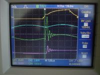
Steve, your point has been proven.
Cheers, Finn Hammer
Finn Hammer, Thu Sept 13 2007, 01:52PM
Steve.
In that case, I should see a current surge on the buss, that doesn`t go into the load.
And it is then this current surge that creates a spike, when it is interrupted, as the freewheling diode finally gets reverse biassed, so that the only current path is through the resonant load, which at this instant of time, looks like an open circuit. This could explain the violent power in that spike.
Ok, out goes the transformers to a remote location. I need space for a Pearson current monitor.
Yellow is gate, for timing reference.
Cyan is current into the resonant load, 2A/Div. The "buttoc curve"

Green is current in Buss, measured between smoothing caps, 2A/Div
Magenta is voltage across IGBT, 20V/Div.

Steve, your point has been proven.
Cheers, Finn Hammer
Re: CCPS (Capacitor Charging Power Supply)
ragnar, Thu Sept 13 2007, 03:32PM
RichieB covers well the point on device capacitance proportionality to voltage. This is something I'd intially overlooked in semiconductor datasheets, but came to appreciate very much in my class-E work.
Output and reverse-transfer capacitances do truly vary wildly as you ramp up the (e.g.) drain voltage. In practise, I try to go up 24V, re-evaluate tuning networks/components/deadtimes -- up 24V, re-evaluate tuning networks/components/deadtimes again, and observe which way the components fluctuate. This is severely unscientific, but does establish some personal heuristics I can use in future work. Simulating is probably more rewarding, if I knew how. =-P
Re: CCPS (Capacitor Charging Power Supply)
Finn Hammer, Thu Sept 13 2007, 05:56PM
I greatly appreciate RichieB`s input, Thanks for posting it.
Adding dead time corresponds to reducing drive frequency and duty cycle.
Have a look at this video, showing the effect on current into load, current in buss, and voltage across IGBT`s, as I sweep the frequency from 45.5kHz to 38.5kHz.
The effect is quite dramatic.

I just found another , better operating point, at 40.5kHz, where the duty cycle is really too short, but look how nice and calm everything is, as I ramp voltage up to 300Vbuss.
The Tek6021, monitoring current in the buss, saturates at 15A going negative.

Cheers, Finn Hammer
Finn Hammer, Thu Sept 13 2007, 05:56PM
I greatly appreciate RichieB`s input, Thanks for posting it.
Adding dead time corresponds to reducing drive frequency and duty cycle.
Have a look at this video, showing the effect on current into load, current in buss, and voltage across IGBT`s, as I sweep the frequency from 45.5kHz to 38.5kHz.
The effect is quite dramatic.

I just found another , better operating point, at 40.5kHz, where the duty cycle is really too short, but look how nice and calm everything is, as I ramp voltage up to 300Vbuss.
The Tek6021, monitoring current in the buss, saturates at 15A going negative.

Cheers, Finn Hammer
Re: CCPS (Capacitor Charging Power Supply)
Marko, Thu Sept 13 2007, 07:48PM
Sorry Steve, I can swear to gods I didn't. You aren't blocked, I'm just trying to figure out what's happening
Marko, Thu Sept 13 2007, 07:48PM
PS: Marko, I sent you a couple of PMs, did you not receive them? Is your inbox full?
Sorry Steve, I can swear to gods I didn't. You aren't blocked, I'm just trying to figure out what's happening

Re: CCPS (Capacitor Charging Power Supply)
Steve Ward, Thu Sept 13 2007, 07:48PM
The device capacitance got me too when i was looking at my CM300 DRSSTC bridge. I noted that my voltage overshoot was dramatic at low DC input, but fell off as i actually approached a few hundred volts across the IGBTs. At the time i wasnt sure if it was real or if it was my probes, but since my IGBTs dont seem to blow up anymore, i figured the overshoot really was dropping off. Diode recovery was still a big issue, and slowing down the switching only helped moderately.
Re: CCPS (Capacitor Charging Power Supply)
Finn Hammer, Fri Sept 14 2007, 09:30PM
Steve, Richie, all
The reason for turning the swiches on at exactly 1/2 the resonant frequency was simply because everybody that I had read about at that time, did so.
The idea of introducing dead time seems compelling, and at first point I fell for it, but it seems like only 1/2 the truth that I can apply any amount of dead time btwn. complete current cycles.
Today, I hooked one set of IGBT`s up to the pulse generator, to better see what happens when only one single pulse is allowed to draw current. The situation is the one where the supply is starting to charge an empty capacitor. It will look different at the end of the charging cycle.
Yellow is gate, Cyan is current into resonant load, and Magenta is voltage acros the opposing swich in the leg.
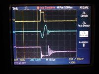
As the gate is taken positive the IGBT starts to conduct, as shown in the negative going current cycle. At the same time, full buss voltage is applied to the opposing IGBT as seen on Magenta trace. Shortly after the current has transferred to the freewheling diode, the gate goes negative, closing the IGBT.
When the current passes trough zero, it slams against the closed IGBT`s, the charge is trapped, and starts to oscillate. When the oscillation dies down, a bit more than half the bus voltage is deposited on the resonant cap. I guess the rest has been burned off in heat. I am not too sure about what really happens.....
Adding dead time robs me of my ZCS, unles I throw the swich at exactly 1.7uS deadtime:
Zooming in on the previous scopeshot, shows this, yellow cursors on Cyan trace:
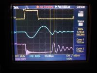
Since the native frequency is 47.2kHz, the 1/2 period time is 10.6uS. Add 1.7uS and the half period time is 12.3uS corresponding to a drive frequency of 40.6kHz, the frequency I found experimentally yesterday.
And which looks like this:
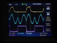
Perhaps it is time to build that super low inductance buss that will prevent current measurements, for lack of a rogowsky based system, slap the IGBT`s on a tunnel type heat sink, coz they do get warm, and try to ramp the voltage towards the 560 volts.
I would like to hear more about the "Pulse thinning method", and adding dead time in general, since it looks like it is not totally troublefree.
Cheers, Finn Hammer
Finn Hammer, Fri Sept 14 2007, 09:30PM
Steve Conner wrote ...
Finn,
*edit* I got this from Richie by e-mail:
Finn,
*edit* I got this from Richie by e-mail:
richie wrote ...
Hi Steve,
snip
The only thing that seems strange is that he is trying to turn on the opposing
switch immediately after the first complete current cycle ends. You have all
the time in the world after this point, the only thing you sacrifice is a small
amount of power by introducing deadtime here. You remember the "pulse thinning
out" method of average-current control we talked about?
snip.
Steve, Richie, all
The reason for turning the swiches on at exactly 1/2 the resonant frequency was simply because everybody that I had read about at that time, did so.
The idea of introducing dead time seems compelling, and at first point I fell for it, but it seems like only 1/2 the truth that I can apply any amount of dead time btwn. complete current cycles.
Today, I hooked one set of IGBT`s up to the pulse generator, to better see what happens when only one single pulse is allowed to draw current. The situation is the one where the supply is starting to charge an empty capacitor. It will look different at the end of the charging cycle.
Yellow is gate, Cyan is current into resonant load, and Magenta is voltage acros the opposing swich in the leg.

As the gate is taken positive the IGBT starts to conduct, as shown in the negative going current cycle. At the same time, full buss voltage is applied to the opposing IGBT as seen on Magenta trace. Shortly after the current has transferred to the freewheling diode, the gate goes negative, closing the IGBT.
When the current passes trough zero, it slams against the closed IGBT`s, the charge is trapped, and starts to oscillate. When the oscillation dies down, a bit more than half the bus voltage is deposited on the resonant cap. I guess the rest has been burned off in heat. I am not too sure about what really happens.....
Adding dead time robs me of my ZCS, unles I throw the swich at exactly 1.7uS deadtime:
Zooming in on the previous scopeshot, shows this, yellow cursors on Cyan trace:

Since the native frequency is 47.2kHz, the 1/2 period time is 10.6uS. Add 1.7uS and the half period time is 12.3uS corresponding to a drive frequency of 40.6kHz, the frequency I found experimentally yesterday.
And which looks like this:

Perhaps it is time to build that super low inductance buss that will prevent current measurements, for lack of a rogowsky based system, slap the IGBT`s on a tunnel type heat sink, coz they do get warm, and try to ramp the voltage towards the 560 volts.
I would like to hear more about the "Pulse thinning method", and adding dead time in general, since it looks like it is not totally troublefree.
Cheers, Finn Hammer
Re: CCPS (Capacitor Charging Power Supply)
Steve Conner, Sat Sept 15 2007, 08:48AM
Hi Finn,
In the experiment you did with the single pulse, the waveforms are quite OK. The ringing at the end looks awful, but it doesn't do any harm.
The only thing to do is make the pulse a little longer so you can be sure the current has commutated to the diode before you turn the IGBT off. Richie suggested turning off halfway through the second half cycle to buy some tolerance. This entire half-cycle flows in diodes, not IGBTs, so any switching instant during it will result in both ZCS and ZVS. When you widen the pulse the other waveforms shouldn't change at all! I'm still pestering him to join 4hv :P
Re: CCPS (Capacitor Charging Power Supply)
Marko, Sat Sept 15 2007, 09:27AM
Hey, you guys are awesome. I never actually realized that there's nothing preventing you from turning the IGBT off while the diode is in conduction anyway. TUrning it off to early may actually cause problems.
I see the point in it. You can actually switch halfway into the freewheeling cycle and have both ZCS and ZVS as far as I see. So even changing the duty cycle or frequency doesn't matter much within limits.
The only 'odd' thing I notice is apparent overshoot of humpy current waveform over zero. (I tought it needs to just touch zero). And it seems to have no effect at all..?
Re: CCPS (Capacitor Charging Power Supply)
Finn Hammer, Sat Sept 15 2007, 11:48AM
Awfull indeed. I was worried about the apparent DC bias it placed on the transformer....perhaps....
That`s correct. A bit longer pulse is better.

It should just touch zero, but driving below 1/2 res makes it ring a bit past zero. this is in order to let the freewheling diode recover, to avoid much worse shoot trough.
I don`t know if it is good or bad, but I cannot seem to avoid it.....
This becomes a problem due to the big relatively slow bricks we are using. It would probably not be visible in an array of smaller, faster, IGBT`s, also known as a MUMISSS (MUlti MIni Solid State Switch). =:-o
Cheers, Finn Hammer
I guess spirit is high when acronymuslike abbreviations come to mind.
Finn Hammer, Sat Sept 15 2007, 11:48AM
Steve Conner wrote ...
Hi Finn,
In the experiment you did with the single pulse, the waveforms are quite OK. The ringing at the end looks awful, but it doesn't do any harm.
Hi Finn,
In the experiment you did with the single pulse, the waveforms are quite OK. The ringing at the end looks awful, but it doesn't do any harm.
Awfull indeed. I was worried about the apparent DC bias it placed on the transformer....perhaps....

Steve Conner wrote ...
The only thing to do is make the pulse a little longer so you can be sure the current has commutated to the diode before you turn the IGBT off. Richie suggested turning off halfway through the second half cycle to buy some tolerance. This entire half-cycle flows in diodes, not IGBTs, so any switching instant during it will result in both ZCS and ZVS. When you widen the pulse the other waveforms shouldn't change at all!
The only thing to do is make the pulse a little longer so you can be sure the current has commutated to the diode before you turn the IGBT off. Richie suggested turning off halfway through the second half cycle to buy some tolerance. This entire half-cycle flows in diodes, not IGBTs, so any switching instant during it will result in both ZCS and ZVS. When you widen the pulse the other waveforms shouldn't change at all!
That`s correct. A bit longer pulse is better.
Steve Conner wrote ...
I'm still pestering him to join 4hv :P
Don`t stop untill he does.I'm still pestering him to join 4hv :P
Marko wrote ...
The only 'odd' thing I notice is apparent overshoot of humpy current waveform over zero. (I tought it needs to just touch zero). And it seems to have no effect at all..?
I call it the "buttoc" waveform The only 'odd' thing I notice is apparent overshoot of humpy current waveform over zero. (I tought it needs to just touch zero). And it seems to have no effect at all..?

It should just touch zero, but driving below 1/2 res makes it ring a bit past zero. this is in order to let the freewheling diode recover, to avoid much worse shoot trough.
I don`t know if it is good or bad, but I cannot seem to avoid it.....
This becomes a problem due to the big relatively slow bricks we are using. It would probably not be visible in an array of smaller, faster, IGBT`s, also known as a MUMISSS (MUlti MIni Solid State Switch). =:-o
Cheers, Finn Hammer
I guess spirit is high when acronymuslike abbreviations come to mind.

Re: CCPS (Capacitor Charging Power Supply)
Experimentonomen, Sat Sept 15 2007, 12:31PM
I think Richie is too busy to have time to join 4hv, since he cannot even maintain his web site anymore.
Experimentonomen, Sat Sept 15 2007, 12:31PM
I think Richie is too busy to have time to join 4hv, since he cannot even maintain his web site anymore.
Re: CCPS (Capacitor Charging Power Supply)
Finn Hammer, Sun Sept 16 2007, 06:01PM
All,
I prefer to think that Richies website is a textbook example in website excellence, not likely to become the target of dis-satisfaction.
Anyway, today we took the the supply totally apart, in order to manifest "Iteration no. 3".
I had previously decided to settle on an operating point with one deadtime ripple, so that the turn on of the IGBT`s became ZCS, and as we already know now, the turn offs are both ZVS and ZCS, so the supply could run in idle, with 25A on both cycles, without getting even luke warm.
A lesson in swiching loses.
To make sure we could handle the heat associated with 200 peak amps in this iteration, we installed the best heatsink I had in stock: This should be able to handle gracefully, the 400-600W we expect to create in heat.
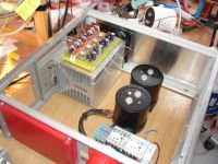
This process involved cutting a lot of threads. Many times have I witnessed people on these boards complain about the troubles of cutting threads, so I thought this might be the right time to share with you, how i do it.

I`l be back with an update as soon as the internal wiring has come back in.
Cheers, Finn Hammer
Finn Hammer, Sun Sept 16 2007, 06:01PM
All,
I prefer to think that Richies website is a textbook example in website excellence, not likely to become the target of dis-satisfaction.
Anyway, today we took the the supply totally apart, in order to manifest "Iteration no. 3".
I had previously decided to settle on an operating point with one deadtime ripple, so that the turn on of the IGBT`s became ZCS, and as we already know now, the turn offs are both ZVS and ZCS, so the supply could run in idle, with 25A on both cycles, without getting even luke warm.
A lesson in swiching loses.
To make sure we could handle the heat associated with 200 peak amps in this iteration, we installed the best heatsink I had in stock: This should be able to handle gracefully, the 400-600W we expect to create in heat.

This process involved cutting a lot of threads. Many times have I witnessed people on these boards complain about the troubles of cutting threads, so I thought this might be the right time to share with you, how i do it.

I`l be back with an update as soon as the internal wiring has come back in.
Cheers, Finn Hammer
Re: CCPS (Capacitor Charging Power Supply)
Steve Ward, Sun Sept 16 2007, 06:16PM
Just a side note: letting the IGBTs conduct for longer than a quarter cycle will have impact on the primary current during open circuit conditions. Test to be sure you dont excite some other resonance when the transformer is open circuited. I have found that in order to minimize bad "open circuit" performance you must 1) minimize stray inductance in the transformer itself and 2) carefully choose the operating frequency of the inverter. Under some cases, you might find the open circuit voltage rises far too high for safety. You guys might think im crazy for adding external inductance when you could just integrate it into the transformer itself, but i swear its "different" than you would expect... well at least thats how it worked out with the 3 or 4 of these supplies ive built so far.
Re: CCPS (Capacitor Charging Power Supply)
Finn Hammer, Sun Sept 16 2007, 06:59PM
Steve,
Thanks for your input.
We _are_ going to add external inductance, at least if we can get the leakage inductance of the transformer itself low enough to do so....
We also intend to build voltage monitoring, so that the supply stops before it reaches it`s native top voltage. We have seen effects in simulations, at the end of the charging cycle, which might cover what you describe. It`s not a pretty sight.
You write that we should choose the operating frequency of the inverter with care. We beleive we do so, and relative to the LC resonant frequency of the load, we place it lower, to insert some dead time during which the freewheling diode comes out of conduction. This has already been determined to be important, because otherwise we get shoot through. During this dead time, the energy in the resonant circuit oscillates at a higher frequency, and we let the dead time last for one full cycle of this oscillation, so that we get ZCS at turn on.
However we have yet to see the supply operate at more than 1/4 -1/2 power. We did this with a jacobs ladder . But the jacobs ladder is too unstable for us to extract usefull clues.
We tried to make a salt water resistor as a load, but it also became a short. I guess because we didn`t have demineralised water, but only ordinary tap water.
Could you expand on which parameters you optimise for, when you choose the operating frequency?
Cheers, Finn Hammer
Finn Hammer, Sun Sept 16 2007, 06:59PM
Steve Ward wrote ...
Just a side note: letting the IGBTs conduct for longer than a quarter cycle will have impact on the primary current during open circuit conditions. Test to be sure you dont excite some other resonance when the transformer is open circuited. I have found that in order to minimize bad "open circuit" performance you must 1) minimize stray inductance in the transformer itself and 2) carefully choose the operating frequency of the inverter. Under some cases, you might find the open circuit voltage rises far too high for safety. You guys might think im crazy for adding external inductance when you could just integrate it into the transformer itself, but i swear its "different" than you would expect... well at least thats how it worked out with the 3 or 4 of these supplies ive built so far.
Just a side note: letting the IGBTs conduct for longer than a quarter cycle will have impact on the primary current during open circuit conditions. Test to be sure you dont excite some other resonance when the transformer is open circuited. I have found that in order to minimize bad "open circuit" performance you must 1) minimize stray inductance in the transformer itself and 2) carefully choose the operating frequency of the inverter. Under some cases, you might find the open circuit voltage rises far too high for safety. You guys might think im crazy for adding external inductance when you could just integrate it into the transformer itself, but i swear its "different" than you would expect... well at least thats how it worked out with the 3 or 4 of these supplies ive built so far.
Steve,
Thanks for your input.
We _are_ going to add external inductance, at least if we can get the leakage inductance of the transformer itself low enough to do so....

We also intend to build voltage monitoring, so that the supply stops before it reaches it`s native top voltage. We have seen effects in simulations, at the end of the charging cycle, which might cover what you describe. It`s not a pretty sight.
You write that we should choose the operating frequency of the inverter with care. We beleive we do so, and relative to the LC resonant frequency of the load, we place it lower, to insert some dead time during which the freewheling diode comes out of conduction. This has already been determined to be important, because otherwise we get shoot through. During this dead time, the energy in the resonant circuit oscillates at a higher frequency, and we let the dead time last for one full cycle of this oscillation, so that we get ZCS at turn on.
However we have yet to see the supply operate at more than 1/4 -1/2 power. We did this with a jacobs ladder . But the jacobs ladder is too unstable for us to extract usefull clues.
We tried to make a salt water resistor as a load, but it also became a short. I guess because we didn`t have demineralised water, but only ordinary tap water.
Could you expand on which parameters you optimise for, when you choose the operating frequency?
Cheers, Finn Hammer
Re: CCPS (Capacitor Charging Power Supply)
Marko, Sun Sept 16 2007, 09:42PM
Finn, why don't you just use a capacitive load as it would be in order for the supply? It may be noisy, but is the *right* way for the supply to work. You may use water to diischarge and muffle the cap into..?
And you can easily visualize output power by speed it charges the cap. AFAIK, those supplies are actually rated in J/s for power output for capacitor charging. I think it has to do with that it behaves much more like a current than a voltage source.
Re: CCPS (Capacitor Charging Power Supply)
Finn Hammer, Mon Sept 17 2007, 06:25AM
Marco,
I have not built a suitable cap yet, and: (blushing with shame)
The honest answer is that I think slowly.
I would like to sit and watch the scope at prolonged periods, pondering the waveforms, the ringings and such.
If I don`t do this, I will learn nothing, the stuf I build will blow up and I will not have a clue to base the formulation of a question over.
Cheers, Finn Hammer
Finn Hammer, Mon Sept 17 2007, 06:25AM
Marko wrote ...
Finn, why don't you just use a capacitive load as it would be in order for the supply? It may be noisy, but is the *right* way for the supply to work. You may use water to diischarge and muffle the cap into..?
And you can easily visualize output power by speed it charges the cap. AFAIK, those supplies are actually rated in J/s for power output for capacitor charging. I think it has to do with that it behaves much more like a current than a voltage source.
Marco,
I have not built a suitable cap yet, and: (blushing with shame)
The honest answer is that I think slowly.
I would like to sit and watch the scope at prolonged periods, pondering the waveforms, the ringings and such.
If I don`t do this, I will learn nothing, the stuf I build will blow up and I will not have a clue to base the formulation of a question over.
Cheers, Finn Hammer
Re: CCPS (Capacitor Charging Power Supply)
Steve Conner, Mon Sept 17 2007, 12:23PM
In reply to Steve Ward's comment about unsafe open-circuit voltages:
The SLR is designed to drive a load that appears as a short circuit at high frequencies. Its behaviour with an open load is undefined, and as Steve pointed out, undefined usually means smoke.
My solution would be to make sure that the unit never tries to drive an open circuit. Since this is a CCPS, I would integrate the output rectifier, voltage sensor and a small capacitor (maybe as part of a Terry Filter) into the apparatus. Then turning on without a capacitor bank connected will charge the small capacitor very quickly, and the voltage feedback will shut the converter down.
The energy in this capacitor will be wasted in the Terry filter resistor every time the Tesla coil fires, so it should be made as small as possible, provided the open load behaviour stays safe. It really is bad form if your converter catches fire every time you forget to plug it into the Tesla coil.
Marko pointed out a while ago that the behaviour of a SLR converter with a Jacob's Ladder load is also undefined. It sounds like Steve Ward did some work to define it, though, so if you want to make a Jacob's Ladder driver, ask him. (Or just insulate heck out of the transformer and use those "extra resonances" to help get the arc going...)
Richie, if you're reading this, OMGPlz join up
Re: CCPS (Capacitor Charging Power Supply)
Finn Hammer, Tue Sept 18 2007, 05:26AM
Steve,
Thanks for your look into the (hopefully) not too distant future. A Terry filter will be built into the supply for sure, and the idea of a small internal capacitor is good. We sure don`t want to fry the supply every time. =:-O
Now, about running into an open circuit. I have not covered this in detail, like I have not taken scopeshots of it, but from memory, what we saw was a triangle current wave, like in a SSTC, with a ripple overlayed. Ripple ,I think, the same 5-6MHz that seems to be inherent in the supply, due to unaccounted circuit parameters.
I had previously looked at an open circuit as equivalent to a full capacitor, but this is wrong, of course, because the cap, although full at the design top voltage, still is a low impedance load to overshoots.
OTOH, we didn`t just set the jacobs ladder to infinite distance, so whatever abnormalities, they were caught and transferred into plasma.
I`l be good and not hook the supply to a jacob ladder again, unless I want to explore the fact/myth (that the combination JL/CCPS is a catastrophical one) in detail.
Making videoes of the scope shots, showing the effect of parameter changes, voltage or frequency, is new i think.
Any of you guys get usefull information out of that? Should I talk and point out what to look for, would that be better?
Daniel and I are talking about writing the cookbook of CCPS, Based on this supply, and this thread, and we would like to know if the dynamic scopeshots are any good.
Cheers, Finn Hammer
Finn Hammer, Tue Sept 18 2007, 05:26AM
Steve,
Thanks for your look into the (hopefully) not too distant future. A Terry filter will be built into the supply for sure, and the idea of a small internal capacitor is good. We sure don`t want to fry the supply every time. =:-O
Now, about running into an open circuit. I have not covered this in detail, like I have not taken scopeshots of it, but from memory, what we saw was a triangle current wave, like in a SSTC, with a ripple overlayed. Ripple ,I think, the same 5-6MHz that seems to be inherent in the supply, due to unaccounted circuit parameters.
I had previously looked at an open circuit as equivalent to a full capacitor, but this is wrong, of course, because the cap, although full at the design top voltage, still is a low impedance load to overshoots.
OTOH, we didn`t just set the jacobs ladder to infinite distance, so whatever abnormalities, they were caught and transferred into plasma.

I`l be good and not hook the supply to a jacob ladder again, unless I want to explore the fact/myth (that the combination JL/CCPS is a catastrophical one) in detail.
Making videoes of the scope shots, showing the effect of parameter changes, voltage or frequency, is new i think.
Any of you guys get usefull information out of that? Should I talk and point out what to look for, would that be better?
Daniel and I are talking about writing the cookbook of CCPS, Based on this supply, and this thread, and we would like to know if the dynamic scopeshots are any good.
Cheers, Finn Hammer
Re: CCPS (Capacitor Charging Power Supply)
Steve Ward, Tue Sept 18 2007, 06:37AM
The open circuit condition can in fact be very safe and tame, but it can also be catastrophic. I tweak my operating frequency (among other parameters) until im satisfied with the primary current (during O.C.) and open circuit voltage. But, my later controllers allowed a form of PWM control where you can drop the operating frequency and there is a definite voltage peak at a little less than the highest possible frequency (so it should be avoided if possible).
As Conner says, insulate the heck out of it and have fun . Core saturation should really limit the output voltage to some degree but depending on how conservative you were in the design, that could be rather high voltage! Ive seen upward of 30kV on some of my earlier designs that had too much leakage inductance in the transformer.
Steve Ward, Tue Sept 18 2007, 06:37AM
The open circuit condition can in fact be very safe and tame, but it can also be catastrophic. I tweak my operating frequency (among other parameters) until im satisfied with the primary current (during O.C.) and open circuit voltage. But, my later controllers allowed a form of PWM control where you can drop the operating frequency and there is a definite voltage peak at a little less than the highest possible frequency (so it should be avoided if possible).
As Conner says, insulate the heck out of it and have fun
 . Core saturation should really limit the output voltage to some degree but depending on how conservative you were in the design, that could be rather high voltage! Ive seen upward of 30kV on some of my earlier designs that had too much leakage inductance in the transformer.
Re: CCPS (Capacitor Charging Power Supply)
Finn Hammer, Thu Sept 20 2007, 07:22PM
All,
Richie said we should make the gate drive as slow as possible, and since the gate resistors were already 10ohms, the current into the gates is as low as 2A.
Why use a hotrodded DRSSTC worthy gatedriver for that?
Below are gate waveforms for first, the hotrodded driver:
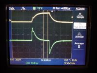
Driving the gates directly from the HP optocouplers shows, that they sink curent slightly worse. They get quite warm too:
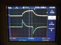
If I remove the 5V negative bias, which I am not sure I need, I get this situation, with cool running opto`s:
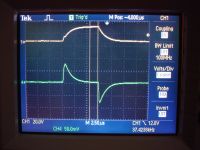
In this the third iteration of the CCPS, I would like to remove all the overkill that sneaked into it, during investigations. The gate driver is one such thing. The low inductance busses were another. We never got an elegant power supply for the gates either, instead we took the term "Breadboarding" way too literal:
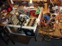
I am going to try out Terry`s source follower supply from his DRSSTC.
Cheers, Finn Hammer
Finn Hammer, Thu Sept 20 2007, 07:22PM
All,
Richie said we should make the gate drive as slow as possible, and since the gate resistors were already 10ohms, the current into the gates is as low as 2A.
Why use a hotrodded DRSSTC worthy gatedriver for that?
Below are gate waveforms for first, the hotrodded driver:

Driving the gates directly from the HP optocouplers shows, that they sink curent slightly worse. They get quite warm too:

If I remove the 5V negative bias, which I am not sure I need, I get this situation, with cool running opto`s:

In this the third iteration of the CCPS, I would like to remove all the overkill that sneaked into it, during investigations. The gate driver is one such thing. The low inductance busses were another. We never got an elegant power supply for the gates either, instead we took the term "Breadboarding" way too literal:


I am going to try out Terry`s source follower supply from his DRSSTC.
Cheers, Finn Hammer
Re: CCPS (Capacitor Charging Power Supply)
Marko, Thu Sept 20 2007, 07:27PM
Aww, why did you remove low-inductance bus? It looked so cool.
Gate drive needs something to be done although... maybe just directly use a larger GDT?
PS. As far as I figured out, terry is powering his drivers from HV bus directly via dropper resistors? Am I looking at right schematic? That exact approach is not going to work in CW unless you are prepared to dissipate huge amounts of power in resistors.
Marko
Re: CCPS (Capacitor Charging Power Supply)
Finn Hammer, Thu Sept 20 2007, 08:06PM
Oh no, it is really elegant. The solid state equivalent to a servo: The source follower.
Here is a schematic:
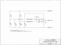
Cheers, Finn Hammer
Finn Hammer, Thu Sept 20 2007, 08:06PM
Marko wrote ...
PS. As far as I figured out, terry is powering his drivers from HV bus directly via dropper resistors? Am I looking at right schematic? That exact approach is not going to work in CW unless you are prepared to dissipate huge amounts of power in resistors.
Marko
PS. As far as I figured out, terry is powering his drivers from HV bus directly via dropper resistors? Am I looking at right schematic? That exact approach is not going to work in CW unless you are prepared to dissipate huge amounts of power in resistors.
Marko
Oh no, it is really elegant. The solid state equivalent to a servo: The source follower.
Here is a schematic:

Cheers, Finn Hammer
Re: CCPS (Capacitor Charging Power Supply)
Marko, Thu Sept 20 2007, 08:32PM
Sorry but I see nothing of elegance.
It is not going to work for CW without a charge pump or some kind of power supply.. DRSSTC is pulsed and really doesn't require much gate drive power, unlike your huge IGBT's in CW.
Looking at rest of terry's schematic I found nothing like that.
As far as I understood it all you are going to dissipate hundreds of watts to get enough drive speed.
Apart from that, opto-drivers are slow. It may not be a problem though.
ANd it doesn't drive the gate negative. I guess I'm misunderstanding at some part.
Marko, Thu Sept 20 2007, 08:32PM
Oh no, it is really elegant. The solid state equivalent to a servo: The source follower.
Here is a schematic:
Sorry but I see nothing of elegance.
It is not going to work for CW without a charge pump or some kind of power supply.. DRSSTC is pulsed and really doesn't require much gate drive power, unlike your huge IGBT's in CW.
Looking at rest of terry's schematic I found nothing like that.
As far as I understood it all you are going to dissipate hundreds of watts to get enough drive speed.
Apart from that, opto-drivers are slow. It may not be a problem though.
ANd it doesn't drive the gate negative. I guess I'm misunderstanding at some part.
Re: CCPS (Capacitor Charging Power Supply)
Finn Hammer, Fri Sept 21 2007, 09:39AM

in R2 which I will make 200ohm, I get 0.1^2 * 200 => 2W
I will put a diode on top of the resistors to keep the caps from discharging while the IGBT is conducting.

Cheers, Finn hammer
Finn Hammer, Fri Sept 21 2007, 09:39AM
Marko wrote ...
Sorry but I see nothing of elegance.
Sorry but I see nothing of elegance.

Marko wrote ...
It is not going to work for CW without a charge pump or some kind of power supply..
It _is_ the power supply. during initial startup, where the supply voltage is ramped up, the 3 caps, are charged to full potential. C1 reaches the zener voltage and forms a bias supply for the mosfet. The mosfet conducts as long as it`s source is more than 5V below this, so the caps c2 and c3 end up with Vzener - 5V on them.It is not going to work for CW without a charge pump or some kind of power supply..
Marko wrote ...
DRSSTC is pulsed and really doesn't require much gate drive power, unlike your huge IGBT's in CW.
The total cate charge is 2uC. at 50kHz that translates into 100mA gate current/avg.DRSSTC is pulsed and really doesn't require much gate drive power, unlike your huge IGBT's in CW.
Marko wrote ...
As far as I understood it all you are going to dissipate hundreds of watts to get enough drive speed.
So for dissipation, I get in R1, which I will make 100K at 560V ,3.5mArms => 1.225WAs far as I understood it all you are going to dissipate hundreds of watts to get enough drive speed.
in R2 which I will make 200ohm, I get 0.1^2 * 200 => 2W
I will put a diode on top of the resistors to keep the caps from discharging while the IGBT is conducting.
Marko wrote ...
Apart from that, opto-drivers are slow. It may not be a problem though.
Slow in what way? The scope shots showed that they can deliver the current, and thay are part of the supply I use at this moment, so speed is no problem. Apart from that, opto-drivers are slow. It may not be a problem though.

Marko wrote ...
ANd it doesn't drive the gate negative. I guess I'm misunderstanding at some part.
Can you give a good reason why I should need a negative supply?ANd it doesn't drive the gate negative. I guess I'm misunderstanding at some part.
Cheers, Finn hammer
Re: CCPS (Capacitor Charging Power Supply)
Marko, Fri Sept 21 2007, 11:53AM
Ok, this is why I believe against your approach:
Your IGBT's have 30nF gate capacitance max. You inevitably need to charge and dump ( so we don't divide by 2) their energy each cycle, which for say 15 volts is 15^2*30*10^-6 = 0,00000675J, times frequency is 0,3375W.
This gives current of 22.5mA, not much, but wait.
You also need to include driver quiescent current which is 11mA max in this case.
So you need to provide at least like 35mA to power a single driver.
With your 560V bus voltage, losses get colossal.
P = 545*0.035 = 19,075W, times 4 IGBT's!
You need to choose right dropper resistor for this, if you put 100k voltage will sag and IGBT won't turn on completely.
R = 545/I = 15.5k min. You would need some additional margin there.
Terry got out of this because he used small IGBT's with only 3.3nF gate capacitance, lower bus voltage, and only 1-10% duty cycle so his losses were tolerable.
Slow in way of 1,5us switching time, 500ns propagation delay. But since you are slowing your IGBT's down anyway it might not matter, you may also use some slower bricks you couldn't for DRSSTC or something else.
I would just hate to have the IGBT turn on due to ringing when it shouldn't. Everybody drives their IGBT's negative and I always considered it a good habit.
GDT which you are trying so hard to get rid off gives that for free (OK, only during conduction of another IGBT, but that's where it's important) among with excellent speed and ruggedness. And it's probably least overkill of all solutions.
Your IGBT's aren't so big not to be driven by 2 pairs of paralleled UCC's. I've driven 15nF gates to 30V with them in tens of ns rise and fall without problems, you shouldn't have trouble with these at 15V.
Just my $01.
Marko
Marko, Fri Sept 21 2007, 11:53AM
Ok, this is why I believe against your approach:
Your IGBT's have 30nF gate capacitance max. You inevitably need to charge and dump ( so we don't divide by 2) their energy each cycle, which for say 15 volts is 15^2*30*10^-6 = 0,00000675J, times frequency is 0,3375W.
This gives current of 22.5mA, not much, but wait.
You also need to include driver quiescent current which is 11mA max in this case.
So you need to provide at least like 35mA to power a single driver.
With your 560V bus voltage, losses get colossal.
P = 545*0.035 = 19,075W, times 4 IGBT's!
You need to choose right dropper resistor for this, if you put 100k voltage will sag and IGBT won't turn on completely.
R = 545/I = 15.5k min. You would need some additional margin there.
Terry got out of this because he used small IGBT's with only 3.3nF gate capacitance, lower bus voltage, and only 1-10% duty cycle so his losses were tolerable.
Slow in what way? The scope shots showed that they can deliver the current, and thay are part of the supply I use at this moment, so speed is no problem.
Slow in way of 1,5us switching time, 500ns propagation delay. But since you are slowing your IGBT's down anyway it might not matter, you may also use some slower bricks you couldn't for DRSSTC or something else.
Can you give a good reason why I should need a negative supply?
I would just hate to have the IGBT turn on due to ringing when it shouldn't. Everybody drives their IGBT's negative and I always considered it a good habit.
GDT which you are trying so hard to get rid off gives that for free (OK, only during conduction of another IGBT, but that's where it's important) among with excellent speed and ruggedness. And it's probably least overkill of all solutions.
Your IGBT's aren't so big not to be driven by 2 pairs of paralleled UCC's. I've driven 15nF gates to 30V with them in tens of ns rise and fall without problems, you shouldn't have trouble with these at 15V.
Just my $01.
Marko
Re: CCPS (Capacitor Charging Power Supply)
Steve Conner, Fri Sept 21 2007, 02:37PM
Marko, the losses aren't really that colossal, 10-15 watts per IGBT is nothing if you have fan cooling in the chassis. (I guess you guys use commas instead of decimal points and you didn't actually mean 15kW.) But you are right, Terry's source follower supply is just a linear voltage regulator running off the DC bus.
I found that my Odin drivers would drive those bricks CW up to 50kHz, and the power supply drew 0.6A at 20V when powering two drivers hooked up to one halfbridge brick at 25kHz. So it's only twice as efficient as Finn's approach. :/ My drivers waste a lot of current at idle because the rails are regulated by zeners.
Re: CCPS (Capacitor Charging Power Supply)
Marko, Fri Sept 21 2007, 05:48PM
Steve:
I don't know for you guys, but I would hate to have a gate driver circuit which dissipates like 50% of all dissipation of entire machine.
20W per IGBT is actually lower limit, I can hardly see how could he make it better; maybe lower to 12V but not less (driver limit). I narrowed down the margin he would need to use with zeners a bit too much, I think he 'd need few more miliamps for good regulation.
80W is a lot of power to get rid off.
I would avoid that at all costs...
Re: CCPS (Capacitor Charging Power Supply)
Finn Hammer, Sat Sept 22 2007, 06:18PM
Ok, Marco is right....again.
I thought that the sourse follower could regulate without dissipating heat, switch instead of linear, but of course: no free lunch.
So for now, the notion of writing the cookbook of CCPS is off. Come to think of it, what a preposterous idea!
No, why change something that is working perfectly, at least at this stage. Let`s focus on getting a functional design, then, perhaps, we can slim it down.
So the present gate driver stays, and we will install a cute little CCPS which Daniel put together because he had to, I know it`s overkill, but that`s the way to fly:
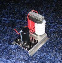
I`l probably even build another low inductance buss just for you, Marco
If this CCPS doesn`t like the load it`s going to work into, smoothing caps loaded by voltage regulators, then I`l just wind that 6-section isolation transformer which I should have done in the first place.
Finally, I`d like to extend my warmest thanks to you all for helping out so far.
This project has taught Daniel and myself so much more than any thing else we have been soldering together.
So much fun, So much more to learn.
Cheers, Finn Hammer
Finn Hammer, Sat Sept 22 2007, 06:18PM
Steve Conner wrote ...
Terry's source follower supply is just a linear voltage regulator running off the DC bus.
andTerry's source follower supply is just a linear voltage regulator running off the DC bus.
Marko wrote ...
Steve:
I don't know for you guys, but I would hate to have a gate driver circuit which dissipates like 50% of all dissipation of entire machine.
80W is a lot of power to get rid off.
I would avoid that at all costs...
Steve:
I don't know for you guys, but I would hate to have a gate driver circuit which dissipates like 50% of all dissipation of entire machine.
80W is a lot of power to get rid off.
I would avoid that at all costs...
Ok, Marco is right....again.
I thought that the sourse follower could regulate without dissipating heat, switch instead of linear, but of course: no free lunch.
So for now, the notion of writing the cookbook of CCPS is off. Come to think of it, what a preposterous idea!
No, why change something that is working perfectly, at least at this stage. Let`s focus on getting a functional design, then, perhaps, we can slim it down.
So the present gate driver stays, and we will install a cute little CCPS which Daniel put together because he had to, I know it`s overkill, but that`s the way to fly:

I`l probably even build another low inductance buss just for you, Marco

If this CCPS doesn`t like the load it`s going to work into, smoothing caps loaded by voltage regulators, then I`l just wind that 6-section isolation transformer which I should have done in the first place.
Finally, I`d like to extend my warmest thanks to you all for helping out so far.
This project has taught Daniel and myself so much more than any thing else we have been soldering together.
So much fun, So much more to learn.
Cheers, Finn Hammer
Re: CCPS (Capacitor Charging Power Supply)
Marko, Sun Sept 23 2007, 09:11AM
Finn he is adorable! And looks quite powerful for it's size. Is it a scale model of sorts? I don't know how much windings are you going to fit into that form.. but still very neat. :)
Marko, Sun Sept 23 2007, 09:11AM
So the present gate driver stays, and we will install a cute little CCPS which Daniel put together because he had to, I know it`s overkill, but that`s the way to fly:
Finn he is adorable! And looks quite powerful for it's size. Is it a scale model of sorts? I don't know how much windings are you going to fit into that form.. but still very neat. :)
Re: CCPS (Capacitor Charging Power Supply)
Finn Hammer, Sun Sept 23 2007, 09:36AM
Yes, a flyback transformer core would probably be more appropriate, but this is what we had handy. The core is from a series choke from a welder.
I think it gives 4 volts per turn, but Daniel knows this.
Cheers, Finn Hammer
Finn Hammer, Sun Sept 23 2007, 09:36AM
Marko wrote ...
Finn he is adorable! And looks quite powerful for it's size. Is it a scale model of sorts? I don't know how much windings are you going to fit into that form.. but still very neat. :)
Finn he is adorable! And looks quite powerful for it's size. Is it a scale model of sorts? I don't know how much windings are you going to fit into that form.. but still very neat. :)
Yes, a flyback transformer core would probably be more appropriate, but this is what we had handy. The core is from a series choke from a welder.
I think it gives 4 volts per turn, but Daniel knows this.
Cheers, Finn Hammer
Re: CCPS (Capacitor Charging Power Supply)
Marko, Sun Sept 23 2007, 11:25AM
Finn, I just love it.
You can increase frequency somewhat more since it's ZCS, especially if you are using smaller IGBT's. As I think you can go to few hundred kHz, as long as you can push enough power through the cap.
Now what are you going to power with it?
Marko, Sun Sept 23 2007, 11:25AM
Finn, I just love it.
You can increase frequency somewhat more since it's ZCS, especially if you are using smaller IGBT's. As I think you can go to few hundred kHz, as long as you can push enough power through the cap.
If this CCPS doesn`t like the load it`s going to work into, smoothing caps loaded by voltage regulators, then I`l just wind that 6-section isolation transformer which I should have done in the first place.
Now what are you going to power with it?

Re: CCPS (Capacitor Charging Power Supply)
Steve Conner, Sun Sept 23 2007, 11:27AM
I get the impression that it's the gate drive power supply
"With gate drive like this, who needs a DC bus"
Steve Conner, Sun Sept 23 2007, 11:27AM
I get the impression that it's the gate drive power supply

"With gate drive like this, who needs a DC bus"

Re: CCPS (Capacitor Charging Power Supply)
Marko, Sun Sept 23 2007, 12:40PM
PS. Why in the world that? One small royer and flyback core are more than enough.. or you want to try something else? Weren't we talking about reducing overkill :p
Marko, Sun Sept 23 2007, 12:40PM
Steve Conner wrote ...
I get the impression that it's the gate drive power supply
"With gate drive like this, who needs a DC bus"
O_________OI get the impression that it's the gate drive power supply

"With gate drive like this, who needs a DC bus"

PS. Why in the world that? One small royer and flyback core are more than enough.. or you want to try something else? Weren't we talking about reducing overkill :p
Re: CCPS (Capacitor Charging Power Supply)
Daniel Uhrenholt, Sun Sept 23 2007, 04:42PM
Hi Steve & Marko.
Yes, it’s the gate drive power supply
I liked the Idea of having a small CCPS driving a monster. The little thing delivers 50J/sec, and the core was used for my first CCPS that was able to deliver 1700J/sec!!!
I use this core because I needed 80 primary turns to get a decent turn ratio, so we have 4 volts per turn. And I think that a flyback core was too small, I needed some wire with decent insulation because it has 320V on the primary.
Here are some scope shots of the primary current:
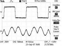
Wee, 1Amp peak in the primary at 320V, I guess IRFP460 Mosfets was a overkill too
And of course it can charge a capacitor
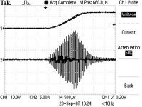
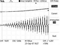
Cheers, Daniel
BTW.
Finn,
About the load to the CCPS, I still have the 4 Mylar caps you gave me a couple of years ago. They are rated 0.25uF 25kV each, so in parallel we have a 1uf cap to play with.
Daniel Uhrenholt, Sun Sept 23 2007, 04:42PM
Hi Steve & Marko.
Yes, it’s the gate drive power supply
I liked the Idea of having a small CCPS driving a monster. The little thing delivers 50J/sec, and the core was used for my first CCPS that was able to deliver 1700J/sec!!!
I use this core because I needed 80 primary turns to get a decent turn ratio, so we have 4 volts per turn. And I think that a flyback core was too small, I needed some wire with decent insulation because it has 320V on the primary.
Here are some scope shots of the primary current:

Wee, 1Amp peak in the primary at 320V, I guess IRFP460 Mosfets was a overkill too
And of course it can charge a capacitor


Cheers, Daniel
BTW.
Finn,
About the load to the CCPS, I still have the 4 Mylar caps you gave me a couple of years ago. They are rated 0.25uF 25kV each, so in parallel we have a 1uf cap to play with.
Re: CCPS (Capacitor Charging Power Supply)
Marko, Sun Sept 23 2007, 05:03PM
I don't see any point (unless your point was to make others not to see the point). You need like a watt or two in overall at 15V for your gate supply, you could do it with an iron cored transformer smaller and lighter than that thing, or a royer oscillator driving a tiny ferrite core.
It's just a heavy Rube Goldberg machine this way , much more things to get broken and to debug. Seriously, I would focus on perfecting the big one first
Marko, Sun Sept 23 2007, 05:03PM
I don't see any point (unless your point was to make others not to see the point). You need like a watt or two in overall at 15V for your gate supply, you could do it with an iron cored transformer smaller and lighter than that thing, or a royer oscillator driving a tiny ferrite core.
It's just a heavy Rube Goldberg machine this way
 , much more things to get broken and to debug. Seriously, I would focus on perfecting the big one first
Re: CCPS (Capacitor Charging Power Supply)
Finn Hammer, Sun Sept 23 2007, 10:26PM
Marco, all
Daniel and I have a facination for industrial art, we see it as much as sculpture as anything else. Efficiency is not our main design target, although your points on thermal efficiency in the gate drive are well taken.
And then our arsenal of electronic solutions are limited.
For example, a royer oscillator. I know there is one in my scope, driving the flouresent tube that lights the display. because the first time I successfully repaired an electronic device was finding the defective cap in said supply.
But design one, I can`t.
Cheers, Finn Hammer
Finn Hammer, Sun Sept 23 2007, 10:26PM
Marko wrote ...
I don't see any point (unless your point was to make others not to see the point).
I don't see any point (unless your point was to make others not to see the point).

Marco, all
Daniel and I have a facination for industrial art, we see it as much as sculpture as anything else. Efficiency is not our main design target, although your points on thermal efficiency in the gate drive are well taken.
And then our arsenal of electronic solutions are limited.
For example, a royer oscillator. I know there is one in my scope, driving the flouresent tube that lights the display. because the first time I successfully repaired an electronic device was finding the defective cap in said supply.
But design one, I can`t.
Cheers, Finn Hammer
Re: CCPS (Capacitor Charging Power Supply)
Finn Hammer, Tue Sept 25 2007, 08:36PM
I just whipped a Mazilli driver together, and I don`t regret it.
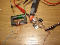
The resonant frequency is determined by the primary L and Parallel C.
I tried it with 3 values of paralell caps. 10nF, 100nF and 1uF.
Resonant frequencies, 140kHz, 47kHz and 14.6kHz.
I measured the primary L to 76uH, so the resonant frequencies don`t match the expected frequency completely, but clearly a connection.
It delivers plenty of power, is small and neat.
We will be using such one supply for the Gate driver. Since it is isolated from the line, which probably is dirty when the coil is running, I will probably also run the voltage probe with one.
It is very satisfying to see a Mazilli oscillator in action for the first time. I just got aquainted with the term "household supply" and this sure is a nice one.
Cheers, Finn hammer
Finn Hammer, Tue Sept 25 2007, 08:36PM
Finn Hammer wrote ...
And then our arsenal of electronic solutions are limited.
For example, a royer oscillator. I know there is one in my scope, driving the flouresent tube that lights the display. because the first time I successfully repaired an electronic device was finding the defective cap in said supply.
But design one, I can`t.
Cheers, Finn Hammer
I just whipped a Mazilli driver together, and I don`t regret it.

The resonant frequency is determined by the primary L and Parallel C.
I tried it with 3 values of paralell caps. 10nF, 100nF and 1uF.
Resonant frequencies, 140kHz, 47kHz and 14.6kHz.
I measured the primary L to 76uH, so the resonant frequencies don`t match the expected frequency completely, but clearly a connection.
It delivers plenty of power, is small and neat.
We will be using such one supply for the Gate driver. Since it is isolated from the line, which probably is dirty when the coil is running, I will probably also run the voltage probe with one.
It is very satisfying to see a Mazilli oscillator in action for the first time. I just got aquainted with the term "household supply" and this sure is a nice one.
Cheers, Finn hammer
Re: CCPS (Capacitor Charging Power Supply)
Steve Conner, Wed Sept 26 2007, 10:10AM
Yay, glad the Mazzilli oscillator worked for you. I used one to power my IGBT gate drivers too. IIRC, it runs at 60kHz and has a 68nF resonant cap.
It was only designed for DRSSTC duty, but it turned out to be able to drive a 300A brick CW at over 30kHz.
BTW, nice current probe, where did you get that? :)
Re: CCPS (Capacitor Charging Power Supply)
Finn Hammer, Wed Sept 26 2007, 05:18PM
EBay.
They show up every once in a while. I`ve got the 134 amplifier that goes with it, so with the scope at 50mA/div., it can do from 1A/Div. to 1mA/div. "up to 50mHz.
All I really need is a Rogowski coil based system, for those hard to get at places.
(I guess "need " is a relative word. Being the tool fetichist I am, perhaps "Would like to have" is better.
They never show up on EBay, though, and cost 800UKP, so that`s an investment for the future.
Cheers, Finn Hammer
edit
With full wave rectification, 100nF cap, 75kHz, and a healthy airgap in the core
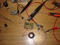
It is doing 1.3Arms into 30Volts here:
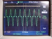
which is enough to drive both bricks with 10ohm gate resistors CW to 300kHz as calculated with SEMIKRON`s own driver selection tool:

Cheers, Finn Hammer
Finn Hammer, Wed Sept 26 2007, 05:18PM
Steve Conner wrote ...
BTW, nice current probe, where did you get that? :)
BTW, nice current probe, where did you get that? :)
EBay.
They show up every once in a while. I`ve got the 134 amplifier that goes with it, so with the scope at 50mA/div., it can do from 1A/Div. to 1mA/div. "up to 50mHz.
All I really need is a Rogowski coil based system, for those hard to get at places.
(I guess "need " is a relative word. Being the tool fetichist I am, perhaps "Would like to have" is better.
They never show up on EBay, though, and cost 800UKP, so that`s an investment for the future.
Cheers, Finn Hammer
edit
Steve Conner wrote ...
Yay, glad the Mazzilli oscillator worked for you. I used one to power my IGBT gate drivers too. IIRC, it runs at 60kHz and has a 68nF resonant cap.
It was only designed for DRSSTC duty, but it turned out to be able to drive a 300A brick CW at over 30kHz.
Yay, glad the Mazzilli oscillator worked for you. I used one to power my IGBT gate drivers too. IIRC, it runs at 60kHz and has a 68nF resonant cap.
It was only designed for DRSSTC duty, but it turned out to be able to drive a 300A brick CW at over 30kHz.
With full wave rectification, 100nF cap, 75kHz, and a healthy airgap in the core

It is doing 1.3Arms into 30Volts here:

which is enough to drive both bricks with 10ohm gate resistors CW to 300kHz as calculated with SEMIKRON`s own driver selection tool:

Cheers, Finn Hammer
Re: CCPS (Capacitor Charging Power Supply)
Finn Hammer, Tue Oct 02 2007, 07:00PM
This is not Show Business, although some of my posts may have reminded you of a soap opera.....
However, I keep strickt adherence to the main rule for amateur entertainers: "Do not quit your day job"
So progress has been slow while I toil to keep the bills payd.
During the building of the Mazilli Driver life was a gravy train.
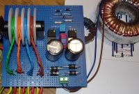
But when we hooked it up to the loaded driver, it became all too clear that Murphy has a major part in this soap.
The power into the driver passes trough 2 pcs. 1n5819 diodes which ought to be more than enough. But not untill we had burned up another set, and finally thrown in uf5408 instead, did the circuit finally show some ruggedness.
Things like this takes a lot of time to debug and set right, and I feel so stupid when it happens. On a day like that, it seems as everything that can go wrong, will go wrong. Just like Murphy said.
Murphy may be an entertainer, but I don`t like his act.
Cheers, Finn Hammer
Finn Hammer, Tue Oct 02 2007, 07:00PM
This is not Show Business, although some of my posts may have reminded you of a soap opera.....
However, I keep strickt adherence to the main rule for amateur entertainers: "Do not quit your day job"
So progress has been slow while I toil to keep the bills payd.
During the building of the Mazilli Driver life was a gravy train.

But when we hooked it up to the loaded driver, it became all too clear that Murphy has a major part in this soap.
The power into the driver passes trough 2 pcs. 1n5819 diodes which ought to be more than enough. But not untill we had burned up another set, and finally thrown in uf5408 instead, did the circuit finally show some ruggedness.
Things like this takes a lot of time to debug and set right, and I feel so stupid when it happens. On a day like that, it seems as everything that can go wrong, will go wrong. Just like Murphy said.
Murphy may be an entertainer, but I don`t like his act.
Cheers, Finn Hammer
Re: CCPS (Capacitor Charging Power Supply)
Sulaiman, Tue Oct 02 2007, 07:19PM
Finn, that is a horrible waveform you've got there, I usually get a nice smooth sinewave (less emi/rfi problems)
I'm a little dubious of the very small series/dc inductor you've got there
just as a test try a small reel of wire as an air-cored inductor
if the waveform improves then you know what to do.
You may also want to try try adding some more parallel/resonant capacitance which will lower the resonant frequency
and minimize switching delay effects.
Re: CCPS (Capacitor Charging Power Supply)
Marko, Tue Oct 02 2007, 09:46PM
Thou shall not use ferrite toroids for series inductor.
You need powdered iron core or largely gapped (rod) ferrite.
Why did you use multifilar windings for your secondaries? I can hardly imagine why would you need more than single wire for that power.
Marko, Tue Oct 02 2007, 09:46PM
Thou shall not use ferrite toroids for series inductor.
You need powdered iron core or largely gapped (rod) ferrite.
Why did you use multifilar windings for your secondaries? I can hardly imagine why would you need more than single wire for that power.
Re: CCPS (Capacitor Charging Power Supply)
Finn Hammer, Wed Oct 03 2007, 05:55AM
Thanks for looking so closely. The incuctor below the circuit board is actually the one in service. Although the one on the board has the same inductance, it probably saturates, or somethng, at higher power levels.
Cheers, Finn Hammer
Finn Hammer, Wed Oct 03 2007, 05:55AM
Sulaiman wrote ...
Finn, that is a horrible waveform you've got there, I usually get a nice smooth sinewave (less emi/rfi problems)
This waveform is with the driver into a smoothing cap and a 30ohm resistor, to test it`s ability to deliver power. Without the resistor I get nice sine wave.Finn, that is a horrible waveform you've got there, I usually get a nice smooth sinewave (less emi/rfi problems)
Sulaiman wrote ...
I'm a little dubious of the very small series/dc inductor you've got there
just as a test try a small reel of wire as an air-cored inductor
if the waveform improves then you know what to do.
I'm a little dubious of the very small series/dc inductor you've got there
just as a test try a small reel of wire as an air-cored inductor
if the waveform improves then you know what to do.
Thanks for looking so closely. The incuctor below the circuit board is actually the one in service. Although the one on the board has the same inductance, it probably saturates, or somethng, at higher power levels.
Marko wrote ...
Thou shall not use ferrite toroids for series inductor.
You need powdered iron core or largely gapped (rod) ferrite.
I never found out quite what`s the difference. How can I tell the difference?Thou shall not use ferrite toroids for series inductor.
You need powdered iron core or largely gapped (rod) ferrite.
Marko wrote ...
Why did you use multifilar windings for your secondaries? I can hardly imagine why would you need more than single wire for that power.
I didn`t. It is a centertap commimg out. There is a + 24volt, -05volt supply to cater for.Why did you use multifilar windings for your secondaries? I can hardly imagine why would you need more than single wire for that power.
Cheers, Finn Hammer
Re: CCPS (Capacitor Charging Power Supply)
Steve Conner, Wed Oct 03 2007, 09:57AM
Hey Finn, just to say that Richie thinks you should lower your CCPS switching frequency to 20kHz. (ie, tune the resonant network to 40kHz) There is no single reason, except that it just "makes everything easier"
I also heard that spikes of twice the DC bus voltage are par for the course with IGBT bricks, and the "cure" is to use bricks rated at more than twice the DC bus voltage.
I used a choke-input filter with my Mazzilli PS, and I still get a nice sine wave under load.
Re: CCPS (Capacitor Charging Power Supply)
Finn Hammer, Wed Oct 03 2007, 06:47PM
I don`t know where I had my head when I made that scope shot, because this is what it looks like now.
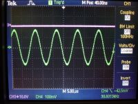
Cheers, Finn Hammer
Finn Hammer, Wed Oct 03 2007, 06:47PM
Steve Conner wrote ...
Hey Finn, just to say that Richie thinks you should lower your CCPS switching frequency to 20kHz. (ie, tune the resonant network to 40kHz) There is no single reason, except that it just "makes everything easier"
Tell Richie he is a mate!Hey Finn, just to say that Richie thinks you should lower your CCPS switching frequency to 20kHz. (ie, tune the resonant network to 40kHz) There is no single reason, except that it just "makes everything easier"
Steve Conner wrote ...
I also heard that spikes of twice the DC bus voltage are par for the course with IGBT bricks, and the "cure" is to use bricks rated at more than twice the DC bus voltage.
Well, with the dead time I feel confident that I can keep the spikes below that, but it sure is a releif to know that it is the norm, and not just Murphy playing tricks with me.I also heard that spikes of twice the DC bus voltage are par for the course with IGBT bricks, and the "cure" is to use bricks rated at more than twice the DC bus voltage.
Steve Conner wrote ...
I used a choke-input filter with my Mazzilli PS, and I still get a nice sine wave under load.
I used a choke-input filter with my Mazzilli PS, and I still get a nice sine wave under load.
I don`t know where I had my head when I made that scope shot, because this is what it looks like now.

Cheers, Finn Hammer
Re: CCPS (Capacitor Charging Power Supply)
Finn Hammer, Sun Oct 21 2007, 02:29PM
All,
We have not given up completely at all, just like, you know, A guy`s gotta eat, so the day job thing.....
Anyway, we have been working on getting a PCB manufacturing act together. We really need that ground plane on the controllers and stuff, so 2 sided photosensitive material formed the base for these 2 boards:
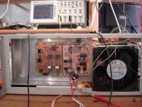
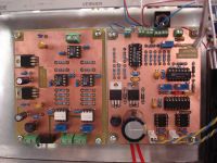
The board to the left is the voltage probe, and to the right is the controller board.
It contains the 494 PWM oscillator which interfaces with the gate driver board trough dual UCC37xxx.
Up front of it is a 74HC74 FF which takes care of synchronizing the start and stop of the pulse trains.
Further up front is a LM339 quad comparator of which each of them can clamp the data pin low, for Voltage stop, Kill Switch stop, Over temp stop, and a delay stop, so that the charging starts a predetermined time after the tesla coil has rung down.
Speaking of the Gate driver.
Now that the rest of the control circuitry is acquiring a half decent appearance, proper PCB`s and all, and since we are down to driving the gates right off the optocoupler anyway, the dinosaur beefy driver is going into the bin, and a nice PCB is being made for the gate driver as well.
If the input to the beefy driver goes open, it settles into the high state, where all 4 IGBT`s are on, so we feel more comfortable with the opto`s which have to be forced to go high.
We plan to lower the frequency as suggested by Richie Burnett, so they run quite cool, properly heatsunk. Sinked?
Comments and suggestions are as always, very welcome.
Cheers, Finn & Daniel
Finn Hammer, Sun Oct 21 2007, 02:29PM
All,
We have not given up completely at all, just like, you know, A guy`s gotta eat, so the day job thing.....
Anyway, we have been working on getting a PCB manufacturing act together. We really need that ground plane on the controllers and stuff, so 2 sided photosensitive material formed the base for these 2 boards:


The board to the left is the voltage probe, and to the right is the controller board.
It contains the 494 PWM oscillator which interfaces with the gate driver board trough dual UCC37xxx.
Up front of it is a 74HC74 FF which takes care of synchronizing the start and stop of the pulse trains.
Further up front is a LM339 quad comparator of which each of them can clamp the data pin low, for Voltage stop, Kill Switch stop, Over temp stop, and a delay stop, so that the charging starts a predetermined time after the tesla coil has rung down.
Speaking of the Gate driver.
Now that the rest of the control circuitry is acquiring a half decent appearance, proper PCB`s and all, and since we are down to driving the gates right off the optocoupler anyway, the dinosaur beefy driver is going into the bin, and a nice PCB is being made for the gate driver as well.
If the input to the beefy driver goes open, it settles into the high state, where all 4 IGBT`s are on, so we feel more comfortable with the opto`s which have to be forced to go high.
We plan to lower the frequency as suggested by Richie Burnett, so they run quite cool, properly heatsunk. Sinked?
Comments and suggestions are as always, very welcome.
Cheers, Finn & Daniel
Re: CCPS (Capacitor Charging Power Supply)
Finn Hammer, Mon Feb 11 2008, 06:36PM
Wow, I sure had to look _way_ back to find an entry to this thread.
Most of the controll electronics into it`s 3rd iteration, and in compliance with current standards (Goldilock gate drive, etc. ) the transformer was next in line for a redesign.
We had listened to Richie at the Cambridge teslathon, and I had bought the book, Soft Ferrites by E. C. Snelling.
Last weekend we made litz wire (16 strands of 0.25mm wire, 4 by 4) for the secondary, so now it was time for some kitchen table calculations:
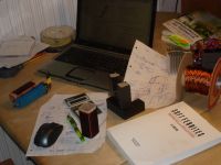
Prior to Cambridge, we had based our transformer on the assumption, that core saturation was the sole limiting factor, when determining the amount volts per turn. Richie told us, that this is not always the case.
After reading the Snelling book, and some of the excellent material at Magnetics website, It became clear that a soft ferrite core is saturation limited up to 20kHz. Beyond 20kHz, the core is loss limited, which means that the core gets too hot if it is driven all the way up to saturation.

Having a look at the loss curves for the material revealed that at 100kHz resonant frequency, the range from 100mW/cm^2 to 400mW/cm^2 corresponded to 100mT to 180mT
We are of the opinion that an oil bath is a good thing, so operating the core at 300mW/cm^2 seemed allright. This means that the core should be driven up to ~160mT
I heard the moan! 100kHz? didn`t I tell you.....
I know it is probably something we are going to regret, but at 100kHz resonant frequency, 50kHz swiching frequency, we are able to process all the power with just one core, so that is what we are going to try...
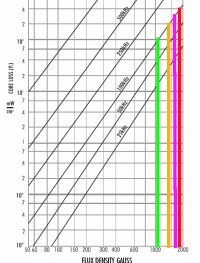
Putting this into the transformer equation:
Npri=Upri/4*B*Amin*f
Solves to 10 turns.
We had 14 turns on the old transformers, so we expect to see some core temperature rise, as we now know is expected and desired.
I had some copper foil left from a welding inverter that didn`t make it to the market:
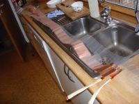
And Daniel brought an Ø80mm bar of machining quality polypropylene, which was machined this weekend:
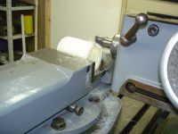
The resulting bobbins are here:
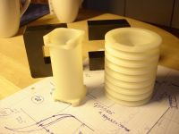
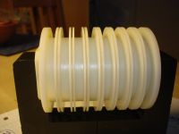
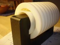
Each secondary section will see 5 layers of 4 turns, for a total of 8 centertapped kilovolts.
Well, that`s about it for now, from the path of an increadible learning experience. We are hell bent to make this thing work, and hopefully for more than just a millisecond, or so. As time will tell in its due course.
Cheers, Finn Hammer
Finn Hammer, Mon Feb 11 2008, 06:36PM
Wow, I sure had to look _way_ back to find an entry to this thread.
Most of the controll electronics into it`s 3rd iteration, and in compliance with current standards (Goldilock gate drive, etc.
 ) the transformer was next in line for a redesign.
We had listened to Richie at the Cambridge teslathon, and I had bought the book, Soft Ferrites by E. C. Snelling.
Last weekend we made litz wire (16 strands of 0.25mm wire, 4 by 4) for the secondary, so now it was time for some kitchen table calculations:

Prior to Cambridge, we had based our transformer on the assumption, that core saturation was the sole limiting factor, when determining the amount volts per turn. Richie told us, that this is not always the case.
After reading the Snelling book, and some of the excellent material at Magnetics website, It became clear that a soft ferrite core is saturation limited up to 20kHz. Beyond 20kHz, the core is loss limited, which means that the core gets too hot if it is driven all the way up to saturation.

Having a look at the loss curves for the material revealed that at 100kHz resonant frequency, the range from 100mW/cm^2 to 400mW/cm^2 corresponded to 100mT to 180mT
We are of the opinion that an oil bath is a good thing, so operating the core at 300mW/cm^2 seemed allright. This means that the core should be driven up to ~160mT
I heard the moan! 100kHz? didn`t I tell you.....
I know it is probably something we are going to regret, but at 100kHz resonant frequency, 50kHz swiching frequency, we are able to process all the power with just one core, so that is what we are going to try...

Putting this into the transformer equation:
Npri=Upri/4*B*Amin*f
Solves to 10 turns.
We had 14 turns on the old transformers, so we expect to see some core temperature rise, as we now know is expected and desired.
I had some copper foil left from a welding inverter that didn`t make it to the market:

And Daniel brought an Ø80mm bar of machining quality polypropylene, which was machined this weekend:

The resulting bobbins are here:


Each secondary section will see 5 layers of 4 turns, for a total of 8 centertapped kilovolts.
Well, that`s about it for now, from the path of an increadible learning experience. We are hell bent to make this thing work, and hopefully for more than just a millisecond, or so.
 As time will tell in its due course.
Cheers, Finn Hammer
Re: CCPS (Capacitor Charging Power Supply)
Marko, Mon Feb 11 2008, 09:08PM
That is one pretty cool transformer finn - glad to see you being back to CCPS work :)
What did you use to carve the 'irregular' bobbin ends?
yes, that is an conclusion I came to too - when trying to puch large amounts of power through small cores I would be limited by heating far sooner than saturation.
No matter what frequency you use and not considering hysteresis losses, it simply seems to be eddy currents in the core - more V/turn you have, larger eddy currents and losses will be regardless of anything, you may have very low max flux density and still overheat the core.
this was just my theory, though.
Other thing, I don't really know why cores heat so much if they get saturated - does hysteresis loss rapidly jump up there?
Marko, Mon Feb 11 2008, 09:08PM
That is one pretty cool transformer finn - glad to see you being back to CCPS work :)
What did you use to carve the 'irregular' bobbin ends?
Prior to Cambridge, we had based our transformer on the assumption, that core saturation was the sole limiting factor, when determining the amount volts per turn. Richie told us, that this is not always the case.
After reading the Snelling book, and some of the excellent material at Magnetics website, It became clear that a soft ferrite core is saturation limited up to 20kHz. Beyond 20kHz, the core is loss limited, which means that the core gets too hot if it is driven all the way up to saturation.
yes, that is an conclusion I came to too - when trying to puch large amounts of power through small cores I would be limited by heating far sooner than saturation.
No matter what frequency you use and not considering hysteresis losses, it simply seems to be eddy currents in the core - more V/turn you have, larger eddy currents and losses will be regardless of anything, you may have very low max flux density and still overheat the core.
this was just my theory, though.
Other thing, I don't really know why cores heat so much if they get saturated - does hysteresis loss rapidly jump up there?
Re: CCPS (Capacitor Charging Power Supply)
Coronafix, Mon Feb 11 2008, 10:46PM
I'd say the milling machine in the photo.
Coronafix, Mon Feb 11 2008, 10:46PM
Marko wrote ...
What did you use to carve the 'irregular' bobbin ends?
What did you use to carve the 'irregular' bobbin ends?
I'd say the milling machine in the photo.
Re: CCPS (Capacitor Charging Power Supply)
Ultra7, Tue Feb 12 2008, 04:53PM
not trying to sound stoopid, but whats CCPS stand for?
Ultra7, Tue Feb 12 2008, 04:53PM
not trying to sound stoopid, but whats CCPS stand for?
Re: CCPS (Capacitor Charging Power Supply)
Finn Hammer, Tue Feb 12 2008, 06:59PM
It means _C_apacitor _C_harging _P_ower _S_upply
It is built on the SLR topology. _S_eries _L_oad _R_esonant.
The latter abbreviation should have been SRL in my opinion, but I was not around when it was coined.
Basically, it is a DRSSTC driver, only driven at a bit less than 1/2 the resonant frequency of the LC resonant load.
Ironically, this supply is going to power a T-BRISG, which will produce shorter sparks than could be acheived if we used the H-Bridge to drive the primary resonator directly.
But that will be for another time.
Cheers, Finn hammer
Finn Hammer, Tue Feb 12 2008, 06:59PM
Ultra7 wrote ...
not trying to sound stoopid, but whats CCPS stand for?
not trying to sound stoopid, but whats CCPS stand for?
It means _C_apacitor _C_harging _P_ower _S_upply
It is built on the SLR topology. _S_eries _L_oad _R_esonant.
The latter abbreviation should have been SRL in my opinion, but I was not around when it was coined.

Basically, it is a DRSSTC driver, only driven at a bit less than 1/2 the resonant frequency of the LC resonant load.
Ironically, this supply is going to power a T-BRISG, which will produce shorter sparks than could be acheived if we used the H-Bridge to drive the primary resonator directly.
But that will be for another time.
Cheers, Finn hammer
Re: CCPS (Capacitor Charging Power Supply)
Dr. Dark Current, Fri Feb 22 2008, 09:16PM
I've read through the thread and I still don't understand one thing, why do I need to use 50% duty cycle on the gates? The free-wheeling current flows through the diode associated to to the same transistor that conducted the preceding halfwave right?
Dr. Dark Current, Fri Feb 22 2008, 09:16PM
I've read through the thread and I still don't understand one thing, why do I need to use 50% duty cycle on the gates? The free-wheeling current flows through the diode associated to to the same transistor that conducted the preceding halfwave right?
Re: CCPS (Capacitor Charging Power Supply)
GeordieBoy, Sat Feb 23 2008, 01:27AM
If you think about it the IGBT's in an SLR inverter actually operate like thyristors: Once they're turned on, they stay on until the current changes direction. And indeed inverter grade thyristors are sometimes used in SLR systems.
+ve load current forced down from V+ through channel of Q1
-ve load current freewheels up to V+ through D1
-ve load current forced down to V- through channel of Q2
+ve load current freewheels up from V- through D2
...rinse and repeat
-Richie,
GeordieBoy, Sat Feb 23 2008, 01:27AM
I've read through the thread and I still don't understand one thing, why do I need to use 50% duty cycle on the gates?There is some latitude in the gate-drive timing to the switches in the SLR inverter because the actual "turn-off" instant of the device is dictated by the resonant frequency of the load - not the gate-drive signal. As long as the gate drive is on for at least half the resonant period, and not on longer than one whole resonant period it works. That makes overall duty ratio for each switch between 0.25 and 0.50 for correct operation.
If you think about it the IGBT's in an SLR inverter actually operate like thyristors: Once they're turned on, they stay on until the current changes direction. And indeed inverter grade thyristors are sometimes used in SLR systems.
The free-wheeling current flows through the diode associated to to the same transistor that conducted the preceding halfwave right?Load current commutation sequence:
+ve load current forced down from V+ through channel of Q1
-ve load current freewheels up to V+ through D1
-ve load current forced down to V- through channel of Q2
+ve load current freewheels up from V- through D2
...rinse and repeat
-Richie,
Re: CCPS (Capacitor Charging Power Supply)
Dr. Dark Current, Sat Feb 23 2008, 02:56PM
Ok, thanks.
I made a small scale "model" with a core from flyback xfmr, worked without problems. However it does not like open circuit loads (as was stated somewhere), the transistors get hot with no load. Any fix for this? Maybe to make the circuit self-tuning?
Re: CCPS (Capacitor Charging Power Supply)
colin heath, Sun Feb 24 2008, 08:53PM
Hi Richie,
Long time no see. Hope you are well?
Sorry to hijack the thread Finn
Cheers
Colin
colin heath, Sun Feb 24 2008, 08:53PM
GeordieBoy wrote ...
If you think about it the IGBT's in an SLR inverter actually operate like thyristors: Once they're turned on, they stay on until the current changes direction. And indeed inverter grade thyristors are sometimes used in SLR systems.
+ve load current forced down from V+ through channel of Q1
-ve load current freewheels up to V+ through D1
-ve load current forced down to V- through channel of Q2
+ve load current freewheels up from V- through D2
...rinse and repeat
-Richie,
I've read through the thread and I still don't understand one thing, why do I need to use 50% duty cycle on the gates?There is some latitude in the gate-drive timing to the switches in the SLR inverter because the actual "turn-off" instant of the device is dictated by the resonant frequency of the load - not the gate-drive signal. As long as the gate drive is on for at least half the resonant period, and not on longer than one whole resonant period it works. That makes overall duty ratio for each switch between 0.25 and 0.50 for correct operation.
If you think about it the IGBT's in an SLR inverter actually operate like thyristors: Once they're turned on, they stay on until the current changes direction. And indeed inverter grade thyristors are sometimes used in SLR systems.
The free-wheeling current flows through the diode associated to to the same transistor that conducted the preceding halfwave right?Load current commutation sequence:
+ve load current forced down from V+ through channel of Q1
-ve load current freewheels up to V+ through D1
-ve load current forced down to V- through channel of Q2
+ve load current freewheels up from V- through D2
...rinse and repeat
-Richie,
Hi Richie,
Long time no see. Hope you are well?
Sorry to hijack the thread Finn

Cheers
Colin
Re: CCPS (Capacitor Charging Power Supply)
Finn Hammer, Sun Feb 24 2008, 09:15PM
Colin,
You are welcome!
Cheers, Finn Hammer
Finn Hammer, Sun Feb 24 2008, 09:15PM
colin heath wrote ...
Hi Richie,
Long time no see. Hope you are well?
Sorry to hijack the thread Finn
Cheers
Colin
Hi Richie,
Long time no see. Hope you are well?
Sorry to hijack the thread Finn

Cheers
Colin
Colin,
You are welcome!
Cheers, Finn Hammer
Re: CCPS (Capacitor Charging Power Supply)
Finn Hammer, Sun Mar 23 2008, 07:33PM
All,
Progress is slow, and with Finn on the starting list on

a lot of training time is expected in the future, which means less time for nerdy electronics.
Anyway, today we sort of finished winding the Transformer.
Here the first layer in the first section is complete.
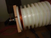
Here is the interleaving, which we use between layers to keep the windings neat.
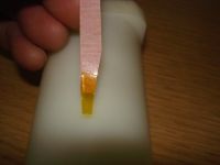
Here you get the picture. There are 4 turns in each layer, and it is best to have a fresh, cylindrical winding base for each layer.
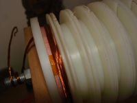
Here you can see how the wire passes from one pie to the next:
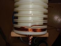
And here is the finished article:
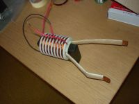
We measued the resonant frequency with a 500nF cap across the primary to be 131kHz, wheach means that we need a small series inductor to get the resonant frequency down to the design frequency of 100kHz.
That`s all for today, folks. A merry easter to you all.
Cheers, Finn and Daniel
Finn Hammer, Sun Mar 23 2008, 07:33PM
All,
Progress is slow, and with Finn on the starting list on

a lot of training time is expected in the future, which means less time for nerdy electronics.
Anyway, today we sort of finished winding the Transformer.
Here the first layer in the first section is complete.

Here is the interleaving, which we use between layers to keep the windings neat.

Here you get the picture. There are 4 turns in each layer, and it is best to have a fresh, cylindrical winding base for each layer.

Here you can see how the wire passes from one pie to the next:

And here is the finished article:

We measued the resonant frequency with a 500nF cap across the primary to be 131kHz, wheach means that we need a small series inductor to get the resonant frequency down to the design frequency of 100kHz.
That`s all for today, folks. A merry easter to you all.
Cheers, Finn and Daniel
Re: CCPS (Capacitor Charging Power Supply)
bob golding, Sun Mar 23 2008, 08:34PM
hi ultra,
this should get you up to speed on ccps topology's

this was a long time before drsstc's solved some problems ,and created some others.:-))
bob golding, Sun Mar 23 2008, 08:34PM
hi ultra,
this should get you up to speed on ccps topology's

this was a long time before drsstc's solved some problems ,and created some others.:-))
Re: CCPS (Capacitor Charging Power Supply)
Finn Hammer, Sun Mar 23 2008, 08:41PM
Thanks, Bob
Yes, needless to say, Marco`s groundbreaking supply paved the way, and was our ultimate inspiration.
I recall when Marco made it, how all this electronic stuff was way over my head, and I guess it still is.....
Cheers, Finn Hammer
Finn Hammer, Sun Mar 23 2008, 08:41PM
bob golding wrote ...
hi ultra,
this should get you up to speed on ccps topology's

this was a long time before drsstc's solved some problems ,and created some others.:-))
hi ultra,
this should get you up to speed on ccps topology's

this was a long time before drsstc's solved some problems ,and created some others.:-))
Thanks, Bob
Yes, needless to say, Marco`s groundbreaking supply paved the way, and was our ultimate inspiration.
I recall when Marco made it, how all this electronic stuff was way over my head, and I guess it still is.....
Cheers, Finn Hammer
Re: CCPS (Capacitor Charging Power Supply)
bob golding, Sun Mar 23 2008, 10:41PM
hi finn,
yes no one else was working on electroric power supplies back then in the dark days of the errrrmm late 1990's i feel a i have got as far as i can with SGTC coils apart from bigger. thats why i am getting into drsstc's as the next logical step now we can get the silicon at sensable prices.think ebay has played a big part in this , as buying al this stuff new is still very expensive. big filter caps are not cheap new. those 5800uF 400 volt ones are 330 euros each at RS!!! hope to see your new ccps at cambridge this year. last weekend of october, will confirm it later.
cheers
bob
Re: CCPS (Capacitor Charging Power Supply)
Dr. Dark Current, Thu Mar 27 2008, 05:05PM
I made a "quick n' dirty" version today. Two fets in halfbridge are driven by GDT and ~40% deadtime. Here is the primary current waveform:
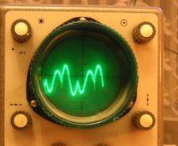
Ok, can anyone explain why the upper "butt" has first pulse smaller than the second, and the bottom "butt" has the first pulse bigger than the second one? The current is small, few A at most, and the Fets are heating quite a bit.
(ignore the negative ringing as it seems to be just some noise picked up by the scope)
Dr. Dark Current, Thu Mar 27 2008, 05:05PM
I made a "quick n' dirty" version today. Two fets in halfbridge are driven by GDT and ~40% deadtime. Here is the primary current waveform:

Ok, can anyone explain why the upper "butt" has first pulse smaller than the second, and the bottom "butt" has the first pulse bigger than the second one? The current is small, few A at most, and the Fets are heating quite a bit.
(ignore the negative ringing as it seems to be just some noise picked up by the scope)
Re: CCPS (Capacitor Charging Power Supply)
Ken M., Thu Mar 27 2008, 05:55PM
I think it has to do with something similar to Class E waveforms, While testing out my idea of Class E\F I noticed rather similar wave forms mostly on the 2ndary side, where the wave form would start going (+) the secondary waveform would get about 30% (+) right as the direct drive fet transitionand from high to low the wave form would do the small butt, dip about 2-5% then shoot back up then go (-) and repeat on the (-) cycle Doing teh Big butt to little butt as teh inverted fet would transition from High to low.
Re: CCPS (Capacitor Charging Power Supply)
Electroholic, Thu Mar 27 2008, 06:17PM
you are driving it at 50% dutycycle. It starts with the 2nd hump of the butt(when you are actually feeding power to it), and then transistors are off, and you see the begining of a ringdown. and they cycle starts all over again in the opposite direction.
Electroholic, Thu Mar 27 2008, 06:17PM
you are driving it at 50% dutycycle. It starts with the 2nd hump of the butt(when you are actually feeding power to it), and then transistors are off, and you see the begining of a ringdown. and they cycle starts all over again in the opposite direction.
Re: CCPS (Capacitor Charging Power Supply)
Finn Hammer, Thu Mar 27 2008, 08:31PM
Plasmaddict
I see what you mean, and although I have no good explanation for it, we have seen the same picture up here several times.
It appears that you are pushing a larger current trough the transformer in one direction than in the other.
I would start by checking the dutycycle for symmetry
It is correct that we see ringdowns. It`s jst that one starts out bigger than the other.
Cheers, Finn Hammer
Finn Hammer, Thu Mar 27 2008, 08:31PM
Plasmaddict wrote ...
Ok, can anyone explain why the upper "butt" has first pulse smaller than the second, and the bottom "butt" has the first pulse bigger than the second one? The current is small, few A at most, and the Fets are heating quite a bit.
Ok, can anyone explain why the upper "butt" has first pulse smaller than the second, and the bottom "butt" has the first pulse bigger than the second one? The current is small, few A at most, and the Fets are heating quite a bit.
Plasmaddict
I see what you mean, and although I have no good explanation for it, we have seen the same picture up here several times.
It appears that you are pushing a larger current trough the transformer in one direction than in the other.
I would start by checking the dutycycle for symmetry
It is correct that we see ringdowns. It`s jst that one starts out bigger than the other.
Cheers, Finn Hammer
Re: CCPS (Capacitor Charging Power Supply)
Finn Hammer, Sun May 11 2008, 03:09PM
All,
We had a bit of progress this wekend, working on the rectifier and the transformer/rectifier oil tank.
The rectifier:
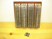
Is 4 strings of 16pcs MUR8100C Which are ultra fast recovery 12A 1000V diodes. And the cheapest diodes we could find in this range.
With a 2.5V forward drop, and an estimated 2A avg. we are looking at up to 80W loss per string, or 320W total rectifier loss.
That`s why we fitted generous heat sinks:
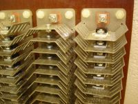
We are already considering to fill the tank with cooking oil, to cater for our needs for fried chips.
To keep things under thermal controll, and also for insulation purposes, we are building an alluminium tank, with heat finns,
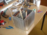
Not welded yet, it will also hold the high voltage transformer.
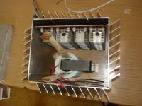
The future progress will be featured in our next installment.
Cheers, Finn Hammer and Daniel Uhrenholt
Finn Hammer, Sun May 11 2008, 03:09PM
All,
We had a bit of progress this wekend, working on the rectifier and the transformer/rectifier oil tank.
The rectifier:

Is 4 strings of 16pcs MUR8100C Which are ultra fast recovery 12A 1000V diodes. And the cheapest diodes we could find in this range.
With a 2.5V forward drop, and an estimated 2A avg. we are looking at up to 80W loss per string, or 320W total rectifier loss.
That`s why we fitted generous heat sinks:

We are already considering to fill the tank with cooking oil, to cater for our needs for fried chips.
To keep things under thermal controll, and also for insulation purposes, we are building an alluminium tank, with heat finns,

Not welded yet, it will also hold the high voltage transformer.

The future progress will be featured in our next installment.
Cheers, Finn Hammer and Daniel Uhrenholt
Re: CCPS (Capacitor Charging Power Supply)
Marko, Sun May 11 2008, 03:37PM
Cheers guys, that tank is looking amazingly bastard! Make sure to put some cool looking bushings and a conservator tank atop of it
Were you thinking about putting the tank capacitor and inductor under oil too? How hot do they get?
Regarding rectifier dissipation:
Have you actually tried putting 2 amps through those diodes and measuring the forward voltage drop?
The 2.5 volt figure you stated seems to be specified for full 12A, and temp of 25 deg. C, at just 2 amps I'd expect it to be much lower, maybe 2x or 3x lower. Temperature rise will reduce the voltage drop too.
Some people are afraid of possible voltage disbalance caused by unequal junction capacitances, and use resistors in parallel with each seriesed diode. I'm not sure how big problem that actually is... but I'd hate to blow such a beautifully (and painfully) constructed diode string.
Marko
Marko, Sun May 11 2008, 03:37PM
Cheers guys, that tank is looking amazingly bastard!
 Make sure to put some cool looking bushings and a conservator tank atop of it
Were you thinking about putting the tank capacitor and inductor under oil too? How hot do they get?
Regarding rectifier dissipation:
Have you actually tried putting 2 amps through those diodes and measuring the forward voltage drop?
The 2.5 volt figure you stated seems to be specified for full 12A, and temp of 25 deg. C, at just 2 amps I'd expect it to be much lower, maybe 2x or 3x lower. Temperature rise will reduce the voltage drop too.
Some people are afraid of possible voltage disbalance caused by unequal junction capacitances, and use resistors in parallel with each seriesed diode. I'm not sure how big problem that actually is... but I'd hate to blow such a beautifully (and painfully) constructed diode string.
Marko
Re: CCPS (Capacitor Charging Power Supply)
Dr. Dark Current, Sun May 11 2008, 03:38PM
Finn, that looks awesome! 0_o
Dr. Dark Current, Sun May 11 2008, 03:38PM
Finn, that looks awesome! 0_o
Re: CCPS (Capacitor Charging Power Supply)
Finn Hammer, Sun May 11 2008, 04:44PM
Curves suggest around 1.3 to 1.5 volts drop, which pleases us immensely.
Cheers, Finn
Finn Hammer, Sun May 11 2008, 04:44PM
Marko wrote ...
Were you thinking about putting the tank capacitor and inductor under oil too? How hot do they get?
No, the cap is staying in the cabinet for now. We have not seen any heating yet, but have not gone to high amperage yet either. Perhaps a CELEM cap will be needed, we`l have to see about that.Were you thinking about putting the tank capacitor and inductor under oil too? How hot do they get?
Marko wrote ...
Regarding rectifier dissipation:
Have you actually tried putting 2 amps through those diodes and measuring the forward voltage drop?
The 2.5 volt figure you stated seems to be specified for full 12A, and temp of 25 deg. C, at just 2 amps I'd expect it to be much lower, maybe 2x or 3x lower. Temperature rise will reduce the voltage drop too.
You are right. I didn`t manage to find the 2.5V figure this time.Regarding rectifier dissipation:
Have you actually tried putting 2 amps through those diodes and measuring the forward voltage drop?
The 2.5 volt figure you stated seems to be specified for full 12A, and temp of 25 deg. C, at just 2 amps I'd expect it to be much lower, maybe 2x or 3x lower. Temperature rise will reduce the voltage drop too.
Curves suggest around 1.3 to 1.5 volts drop, which pleases us immensely.
Marko wrote ...
Some people are afraid of possible voltage disbalance caused by unequal junction capacitances, and use resistors in parallel with each seriesed diode. I'm not sure how big problem that actually is... but I'd hate to blow such a beautifully (and painfully) constructed diode string.
We have been considering this, and there is room for surface mount resistors, so we will perhaps do that.Some people are afraid of possible voltage disbalance caused by unequal junction capacitances, and use resistors in parallel with each seriesed diode. I'm not sure how big problem that actually is... but I'd hate to blow such a beautifully (and painfully) constructed diode string.
Cheers, Finn
Re: CCPS (Capacitor Charging Power Supply)
Steve Conner, Mon May 12 2008, 09:21AM
If the diodes are avalanche rated, there may be no need for balancing resistors. I'd be more worried about the small clearance between all those sharp-cornered heatsinks, even under oil.
Steve Conner, Mon May 12 2008, 09:21AM
If the diodes are avalanche rated, there may be no need for balancing resistors. I'd be more worried about the small clearance between all those sharp-cornered heatsinks, even under oil.
Re: CCPS (Capacitor Charging Power Supply)
GeordieBoy, Mon May 12 2008, 10:30AM
If all diodes are from the same manufacturer, (and ideally from the same LOT code) there should not be a problem. The SLR inverter provides a sinusoidal current to the rectifier bridge so it is less harsh on the secondary-side rectifiers than a hard-switched inverter.
One observation: If you turned the rectifier board through 90 degrees it would allow the cooling liquid to flow more easily between the heatsinks as it rises through convection. Heatsinks in a horizontal orientation across the flow of air (or cooling fluid) don't perform quite as well. Just an observation - surely not a problem.
Oh, and that is one awesome looking cooling tank!
-Richie,
GeordieBoy, Mon May 12 2008, 10:30AM
If all diodes are from the same manufacturer, (and ideally from the same LOT code) there should not be a problem. The SLR inverter provides a sinusoidal current to the rectifier bridge so it is less harsh on the secondary-side rectifiers than a hard-switched inverter.
One observation: If you turned the rectifier board through 90 degrees it would allow the cooling liquid to flow more easily between the heatsinks as it rises through convection. Heatsinks in a horizontal orientation across the flow of air (or cooling fluid) don't perform quite as well. Just an observation - surely not a problem.
Oh, and that is one awesome looking cooling tank!

-Richie,
Re: CCPS (Capacitor Charging Power Supply)
Finn Hammer, Sun Jun 08 2008, 01:07PM
All,
Daniel welded the tank, and brought a nice thick slab of white POM for the lid.
After the 28 holes in the perimeter were drilled, and the corners rounded, the case now looks like this:
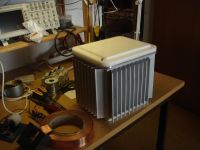
The rectifier and the transformer were positioned on the lid, which looks like this:
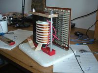
After a lot of headscratching, and catalog browsing, we decided to use a 37 pin circular connector between the primary coil and the switching IGBT`s.

Each pin is good for 13 ARMS so with 15 pins in use each way, there is a little headroom. I have used an identical connector for a disk shooter pulsing in the region of 20kA, and it still can come apart, so this ought to work.
To provide the holes for the connectors, the nice little Wohlhaupter boring head has just done it`s thing again.....
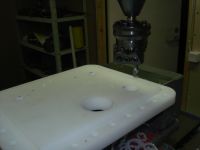
We are waiting for the parts now.....
Cheers, Finn Hammer & Daniel Uhrenholt
Finn Hammer, Sun Jun 08 2008, 01:07PM
All,
Daniel welded the tank, and brought a nice thick slab of white POM for the lid.
After the 28 holes in the perimeter were drilled, and the corners rounded, the case now looks like this:

The rectifier and the transformer were positioned on the lid, which looks like this:

After a lot of headscratching, and catalog browsing, we decided to use a 37 pin circular connector between the primary coil and the switching IGBT`s.

Each pin is good for 13 ARMS so with 15 pins in use each way, there is a little headroom. I have used an identical connector for a disk shooter pulsing in the region of 20kA, and it still can come apart, so this ought to work.
To provide the holes for the connectors, the nice little Wohlhaupter boring head has just done it`s thing again.....

We are waiting for the parts now.....
Cheers, Finn Hammer & Daniel Uhrenholt
Re: CCPS (Capacitor Charging Power Supply)
Dago, Sun Jun 08 2008, 01:24PM
Looks AWESOME!
Dago, Sun Jun 08 2008, 01:24PM
Looks AWESOME!
Re: CCPS (Capacitor Charging Power Supply)
Marko, Sun Jun 08 2008, 03:49PM
Yikes Finn, why so many holes around the rim?
The upside-down design of everything with connectors on the ''floor'' is really clever.
The transformer looks really sexy in that second pic, but I keep wondering if it's secondary winding is a bit overkill?
I thought you were going to use some smaller ceramic bushings for the low voltage in, but the connector is a rather neat solution too.
What kind of bushing are you going to use for HV? And are you going to have some sort of expansion tank for the oil?
Marko
Re: CCPS (Capacitor Charging Power Supply)
Finn Hammer, Sun Jun 08 2008, 06:22PM
That`s to increase the chances of keeping the oil on the inside of the tank, by providing an even pressue on the seal. Of course, oil is likely to wick up trough the multipole connector.....
Overkill? maby. I hope so, because that`s the name of the game
Cheers, Finn Hammer
Finn Hammer, Sun Jun 08 2008, 06:22PM
Dr. Arc flash wrote ...
Yikes Finn, why so many holes around the rim?
Yikes Finn, why so many holes around the rim?
That`s to increase the chances of keeping the oil on the inside of the tank, by providing an even pressue on the seal. Of course, oil is likely to wick up trough the multipole connector.....

Dr. Arc flash wrote ...
The upside-down design of everything with connectors on the ''floor'' is really clever.
The transformer looks really sexy in that second pic, but I keep wondering if it's secondary winding is a bit overkill?
Actually, the "floor" is the lid, so the transformer and rectifier is suspended from the lid rather than standing on the floor.The upside-down design of everything with connectors on the ''floor'' is really clever.
The transformer looks really sexy in that second pic, but I keep wondering if it's secondary winding is a bit overkill?
Overkill? maby. I hope so, because that`s the name of the game

Dr. Arc flash wrote ...
What kind of bushing are you going to use for HV? And are you going to have some sort of expansion tank for the oil?
We are going to use standard N Clamp Plugs for RG213. The RG213 will probably be stripped of it`s outher shell, as well as the braid.What kind of bushing are you going to use for HV? And are you going to have some sort of expansion tank for the oil?
Cheers, Finn Hammer
Re: CCPS (Capacitor Charging Power Supply)
..., Sun Jun 08 2008, 06:32PM
WOW, that is really impressive... I hope you can manage to keep the oil inside the tank. Also, lets hope you don't manage to smoke those diodes since they are going to be impossible to replace...
As to the connector, would it be possible to solder in the wires and then pot the mess in some epoxy/rtv/etc to make sure it is waterproof?
I also do worry a little that as stuff heat up in there you will pressurise the tank, which is going to really test the quality of your seals...
Re: CCPS (Capacitor Charging Power Supply)
Marko, Sun Jun 08 2008, 06:38PM
That is what I meant?
Yeah, I guess it would be OK considering it's on plastic, but don't you think a bushing would look neater? And are you sure that connector is oil-proof? (if everything is going to sink into oil... But I guess some silicone could fix that.
What about expansion of the oil? It is surely going to start leaking out unless it has a vent.
If you wish to have no air in the chamber you should add a expansion tank on the top I guess.
Marko
Marko, Sun Jun 08 2008, 06:38PM
Actually, the "floor" is the lid, so the transformer and rectifier is suspended from the lid rather than standing on the floor.
That is what I meant?
We are going to use standard N Clamp Plugs for RG213. The RG213 will probably be stripped of it`s outher shell, as well as the braid.
Yeah, I guess it would be OK considering it's on plastic, but don't you think a bushing would look neater?
 And are you sure that connector is oil-proof? (if everything is going to sink into oil... But I guess some silicone could fix that.
What about expansion of the oil? It is surely going to start leaking out unless it has a vent.
If you wish to have no air in the chamber you should add a expansion tank on the top I guess.
Marko
Re: CCPS (Capacitor Charging Power Supply)
Finn Hammer, Sun Jun 08 2008, 07:40PM
The N connector is oil proof.
We are leaving about 10mm of air at the top of the tank, so the filler plug will have a felt covered hole for pressure relief.
Cheers, Finn Hammer
Finn Hammer, Sun Jun 08 2008, 07:40PM
Dr. Arc flash wrote ...
That is what I meant?
ok!Actually, the "floor" is the lid, so the transformer and rectifier is suspended from the lid rather than standing on the floor.
That is what I meant?
Dr. Arc flash wrote ...
Yeah, I guess it would be OK considering it's on plastic, but don't you think a bushing would look neater? And are you sure that connector is oil-proof? (if everything is going to sink into oil... But I guess some silicone could fix that.
Bushings would look neat, but I dislike having to use nuts and washers for these connections. Better with a bayonet style plug or in this case, a plug with tne threaded part attached....We are going to use standard N Clamp Plugs for RG213. The RG213 will probably be stripped of it`s outher shell, as well as the braid.
Yeah, I guess it would be OK considering it's on plastic, but don't you think a bushing would look neater?
 And are you sure that connector is oil-proof? (if everything is going to sink into oil... But I guess some silicone could fix that.
The N connector is oil proof.
Dr. Arc flash wrote ...
What about expansion of the oil? It is surely going to start leaking out unless it has a vent.
If you wish to have no air in the chamber you should add a expansion tank on the top I guess.
Marko
What about expansion of the oil? It is surely going to start leaking out unless it has a vent.
If you wish to have no air in the chamber you should add a expansion tank on the top I guess.
Marko
We are leaving about 10mm of air at the top of the tank, so the filler plug will have a felt covered hole for pressure relief.
Cheers, Finn Hammer
Re: CCPS (Capacitor Charging Power Supply)
GeordieBoy, Mon Jun 09 2008, 12:27PM
Finn, do you have anything in place to stop the core pieces from sliding apart sideways? I can see that they are clamped from above, but it might be worth constraining them so they can't move apart sideways. Any shifting of the core halves due to vibration or magnetostriction might otherwise gradually upset the tuning of your SLR inverter. Even a simple spot of glue at the edge of the mated surfaces should be sufficient, and might prevent headaches caused by movement later.
Flyback converters, and SLR to a lesser extent are quite sensitive to relative movement of the core halves or changes in air gap.
-Richie,
Re: CCPS (Capacitor Charging Power Supply)
Finn Hammer, Mon Jun 09 2008, 10:34PM
Thanks for the tip, Richie, I wouldn`t have thought of that. I would be more inclined to keep the cores virgin to facilitate dismantling during post mortem .
.
Anyway, a small glob og silicone glue is now destined to go where it matters.
Cheers, Finn Hammer
Finn Hammer, Mon Jun 09 2008, 10:34PM
GeordieBoy wrote ...
Finn, do you have anything in place to stop the core pieces from sliding apart sideways? I can see that they are clamped from above, but it might be worth constraining them so they can't move apart sideways. Any shifting of the core halves due to vibration or magnetostriction might otherwise gradually upset the tuning of your SLR inverter. Even a simple spot of glue at the edge of the mated surfaces should be sufficient, and might prevent headaches caused by movement later.
Flyback converters, and SLR to a lesser extent are quite sensitive to relative movement of the core halves or changes in air gap.
-Richie,
Thanks for the tip, Richie, I wouldn`t have thought of that. I would be more inclined to keep the cores virgin to facilitate dismantling during post mortem
 .
.Anyway, a small glob og silicone glue is now destined to go where it matters.
Cheers, Finn Hammer
Re: CCPS (Capacitor Charging Power Supply)
GeordieBoy, Mon Jun 09 2008, 10:37PM
Sometimes it helps to keep it so you can dismantle and even investigage the effects of mis-alignment initially. But once it is all working to your satisfaction i'd apply that spot of glue either side, just to make sure nothing drifts over time.
GeordieBoy, Mon Jun 09 2008, 10:37PM
Sometimes it helps to keep it so you can dismantle and even investigage the effects of mis-alignment initially. But once it is all working to your satisfaction i'd apply that spot of glue either side, just to make sure nothing drifts over time.
Re: CCPS (Capacitor Charging Power Supply)
Alex McCown, Tue Jun 10 2008, 01:17AM
when do you expect to show us first light? (aprox. month)
Alex McCown, Tue Jun 10 2008, 01:17AM
when do you expect to show us first light? (aprox. month)
Re: CCPS (Capacitor Charging Power Supply)
Finn Hammer, Wed Jun 11 2008, 06:18PM
First light was long ago. 2nd and 3rd followed in short order.
Anyway, this iteration should shine brightly (hopefully in the right places) within a couple of months.
Present most obvious obstacle is a 3 week leadtime on the resonant capacitors.
Cheers, Finn Hammer
Finn Hammer, Wed Jun 11 2008, 06:18PM
Alex McCown wrote ...
when do you expect to show us first light? (aprox. month)
when do you expect to show us first light? (aprox. month)
First light was long ago. 2nd and 3rd followed in short order.

Anyway, this iteration should shine brightly (hopefully in the right places) within a couple of months.
Present most obvious obstacle is a 3 week leadtime on the resonant capacitors.
Cheers, Finn Hammer
Re: CCPS (Capacitor Charging Power Supply)
uzzors2k, Sat Jun 14 2008, 04:00PM
Amazing work. Those cooling fins make it look like a miniature version of one of those mega power transformers!
uzzors2k, Sat Jun 14 2008, 04:00PM
Amazing work. Those cooling fins make it look like a miniature version of one of those mega power transformers!
Re: CCPS (Capacitor Charging Power Supply)
bob golding, Sat Jun 14 2008, 11:14PM
hi finn will we be seeing your ccps at cambridge this year? last week of october. still need to confirm it with the museum .
bob golding, Sat Jun 14 2008, 11:14PM
hi finn will we be seeing your ccps at cambridge this year? last week of october. still need to confirm it with the museum .
Re: CCPS (Capacitor Charging Power Supply)
Finn Hammer, Sun Jun 15 2008, 06:34AM
Bob,
Daniel and I are definately hoping to have it ready for Cambridge.
Cheers, Finn Hammer
Finn Hammer, Sun Jun 15 2008, 06:34AM
Bob,
Daniel and I are definately hoping to have it ready for Cambridge.
Cheers, Finn Hammer
Print this page