Hard-switched 20kHz Induction Heater Driver
nrhoades, Mon Jul 16 2007, 12:18AMI am making a 20kHz induction heater using control IC's instead of a gate drive transformer. This is my best attempt at a power electronics project... I've used the knowledge I've gathered from this forum and from a few other sources.
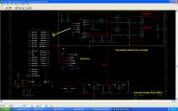
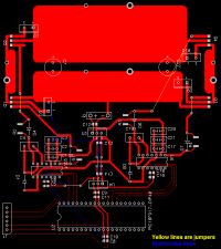
The H-bridge is driven by two IRS2110 half-bridge drivers, both connected to a microcontroller. I tried to make the H-bridge as low inductance as possible... the gates need jumper wires but at 20kHz I think that it won't cause problems. I tried to design it so that TO-220 packages (MOSFET or IGBT's) could be surface soldered for easy replacement. The PCB reflects like the classic H-bridge configuration, with the switches hanging off of the board so they can be attached to a heatsink. J2 is rectified power >15V, and J1 is the ICSP programming port for the PIC.


Re: Hard-switched 20kHz Induction Heater Driver
ragnar, Tue Jul 24 2007, 04:53AM
Bridge looks alright... you may need to shield the controlling circuitry from the power stage, especially if it's hard-switching.
ragnar, Tue Jul 24 2007, 04:53AM
Bridge looks alright... you may need to shield the controlling circuitry from the power stage, especially if it's hard-switching.
Re: Hard-switched 20kHz Induction Heater Driver
nrhoades, Wed Jul 25 2007, 03:39AM
I made the board using a milling machine at work... I don't like it. Soldering is a pain, especially when I accidently short the isolation cuts. The best thing is to have the milling tool remove all islands which kills the life of the bits. I'd rather draw it again by hand or use an iron-on method.
Re: Hard-switched 20kHz Induction Heater Driver
nrhoades, Wed Aug 01 2007, 05:08AM
It didn't work. Back to the drawing board... one day I will finally make a working H-bridge :)
Addition: I wrote a few paragraphs to add to this but they were never appended to this thread. Sorry about that... basically I think the problem may have to do with the charge pump on the 2110. The bottom half of both bridges worked, but there was no signal being sent to the base of the upper halves. I also tested this in haste, and learned how sensitive the gates of mosfets are (latching up and smoke). I don't mind redesigning the whole thing instead of fixing this one because I'm excited to practice making my own pcb boards. Again, sorry about the lack of feedback.
Re: Hard-switched 20kHz Induction Heater Driver
Marko, Wed Aug 01 2007, 11:36AM
No more information for us except 'it didn't work'?
You should be able to easily test both halves of bridge independently. For example, power the bridges with 12VDC and put a DC motor on the output, then try changing it's direction manually. (beware the shoot-trough).
After that it's only about PIC programming, although I don't see any need of it here.
I've used SG3525 alone up to 100kHz with a half bridge. You can increase output stage supply voltage up to 40V and drive pretty large mosfet's with 2:1 or 3:1 stepdown GDT.
2110 chips are rather expensive and not very fast. Your PCB, if not messy, looks like ''waste of copper'' at least. I always try to keep everything as close as possible, and always use up maximum possible copper on the board. It is also much better inductance-wise.
Regarding hard switching, you would need a work coil with very high inductance, wich is troublesome with air core. You will find it next to impossible to insulate such a coil once it heats up to several hundred degrees C.
You will absolutely need a ferrite impedance matching transformer for it.
Re: Hard-switched 20kHz Induction Heater Driver
Tom540, Wed Aug 01 2007, 10:34PM
The problem I see with the layout is you have these fat pools of copper but then they narrow down to skinny traces before they attach to the mosfet pins. You should stick the fets right in the large bodies of copper and use thermal spokes to connect them. I may post a screen shot if I have time tonight.
Print this page