
Crash and burnt coilgun
Speedsoda, Wed Jul 04 2007, 08:33PMWith an emphasis on burnt...
First I just wanna say hi though, I'm new! I've built quite a few spudguns and do alot of interesting gadgets and stuff and just recently figured I'd pick of coilgunning again...
Back to the subject though, I built a pretty jury-rigged coilgun a few days ago that used 3 camera flash circuits and 6 such capacitors connected in parallel(Uhh, what's that, 1500µf @ 300V i think?) and all this connected to a pretty bad coil that i made like 4 years ago, just a plastic pencil-tube wrapped with thin enamel(Laquered? I dunno what it's called) copper wire, probably up too 200 turns or something. I liked that one, it would shoot a piece of a nail about 25 feet, it was much better than my very first which would fire a nail half the size one fourth the distance, but I thought there must be more power to get here... So, since I have a large plastic bag full of disposed disposable cameras I thought it'd be dumb not to use some more of them.
Said and done, I built a gun with 8 flash circuits and 9 caps, it's just that it didn't work. :/ I didn't feel like messing around with eight AA batteries that would probably run out in 15 shots and need replacing, so I connected all the circuits in series and used a small sealed lead acid battery(12 volts, 12/8=1.5V). Though as I switched on the circuits to charge the caps expecting a symphony of those pretty highpitched whines, all I saw was a big grey cloud of smoke being expelled from one of the circuits and out fell a white hot, melted and pretty much totally incinerated transistor from the first circuit on the positive side of the series.
So, uhh... Now I'm just wondering if it was a smart move to connect them all in series? I never thought of the fact that all the current needed for all 8 of those circuits would have to pass through each one of them, was it this that caused the incident? If so, I'd be glad if someone could offer a different solution using that same 12 V battery, and also it'd be nice to know if they can run on 1.7(12v/7) volts instead now that I'm short of one circuit?
Thanks...
Edit: Oh, and is there even the slightest possibility that the other circuits survived the abuse? Or am I gonna have to spend another 4 hours of extracting circuits and soldering tiny wires? :P
Re: Crash and burnt coilgun
J. Aaron Holmes, Wed Jul 04 2007, 10:18PM
Seems certain that you overvolted one or more of them. Placing complex loads in series like this is challenging; you're basically betting that they'll each be presenting the exact same impedance at any particular moment. If they don't (and they probably didn't), then it's like having a voltage divider with a bunch of random-valued resistors; some will see large voltages (and hence draw excessive currents), others not much at all. So some of them will probably "fry", as you observed.
I'm not very familiar with camera flash circuits, but stringing lots of them together seems onerous. If you're already ok with lugging around a 12V lead-acid battery, maybe something inherently more high-voltage would be better. Like a flyback circuit or something. I'm sure somebody else will have some better ideas for you...
Cheers,
Aaron, N7OE
Re: Crash and burnt coilgun
Dalus, Wed Jul 04 2007, 10:50PM
I always use a 555 timer based to create a pulsed voltage (amplefied by an mosfet) which is then fed into a rewound atx transformer out of an old computer powersuply. You could even use the mosfet in the powersuply for this driver. Something like this just substitute the flyback for an atx transformer.
Dalus, Wed Jul 04 2007, 10:50PM
I always use a 555 timer based to create a pulsed voltage (amplefied by an mosfet) which is then fed into a rewound atx transformer out of an old computer powersuply. You could even use the mosfet in the powersuply for this driver. Something like this
 just substitute the flyback for an atx transformer.
Re: Crash and burnt coilgun
Speedsoda, Thu Jul 05 2007, 09:46AM
Makes alot of sense... The circuits came from the same camera models, I ensured that, but still you could see small variations like a slightly different transistor etc so they obviously weren't exactly the same.
Do you think I can expect that the others survived?
Funny, I built that exact driver circuit a few weeks ago, how convenient! I also happen to have a 555 timer circuit adjustable between 5-25khz or something, but I'm guessing the flyback circuit is a better choice?(Or maybe they are pretty much the same, come to think of it) What frequency range is optimal? Though I'm a bit worried, I think I recently burned out the mosfet(I'm not sure, I'm still getting weak sparks from the flyback and sometimes it works great, but at a much lower(15khz maybe), audible frequency.. How do I test the mosfet so I can know for sure if it's that or the flyback that broke?), probably due to overheating, despite the huge heatsink...
I had that idea too, but I couldn't figure out what transformer to use as I'm pretty green when it comes to transformers. I looked around a bit trying to find a suitable core or something that I could wind myself, but it just seemed pointless with all these cameras at hand. :P
So, this atx transformer, where else can I get it, or is there something equivalent to it? I don't think I have a computer power supply around.
Edit: Nuh-uh, this is the flyback circuit I have: ...
I thought I recognized the schematic, but I guess not then.
Speedsoda, Thu Jul 05 2007, 09:46AM
J. Aaron Holmes wrote ...
Seems certain that you overvolted one or more of them. Placing complex loads in series like this is challenging; you're basically betting that they'll each be presenting the exact same impedance at any particular moment. If they don't (and they probably didn't), then it's like having a voltage divider with a bunch of random-valued resistors; some will see large voltages (and hence draw excessive currents), others not much at all. So some of them will probably "fry", as you observed.
Cheers,
Aaron, N7OE
Makes alot of sense... The circuits came from the same camera models, I ensured that, but still you could see small variations like a slightly different transistor etc so they obviously weren't exactly the same.
Do you think I can expect that the others survived?
Dalus wrote ...
I always use a 555 timer based to create a pulsed voltage (amplefied by an mosfet) which is then fed into a rewound atx transformer out of an old computer powersuply. You could even use the mosfet in the powersuply for this driver. Something like this just substitute the flyback for an atx transformer.
I always use a 555 timer based to create a pulsed voltage (amplefied by an mosfet) which is then fed into a rewound atx transformer out of an old computer powersuply. You could even use the mosfet in the powersuply for this driver. Something like this
just substitute the flyback for an atx transformer.Funny, I built that exact driver circuit a few weeks ago, how convenient! I also happen to have a 555 timer circuit adjustable between 5-25khz or something, but I'm guessing the flyback circuit is a better choice?(Or maybe they are pretty much the same, come to think of it) What frequency range is optimal? Though I'm a bit worried, I think I recently burned out the mosfet(I'm not sure, I'm still getting weak sparks from the flyback and sometimes it works great, but at a much lower(15khz maybe), audible frequency.. How do I test the mosfet so I can know for sure if it's that or the flyback that broke?), probably due to overheating, despite the huge heatsink...
I had that idea too, but I couldn't figure out what transformer to use as I'm pretty green when it comes to transformers. I looked around a bit trying to find a suitable core or something that I could wind myself, but it just seemed pointless with all these cameras at hand. :P
So, this atx transformer, where else can I get it, or is there something equivalent to it? I don't think I have a computer power supply around.
Edit: Nuh-uh, this is the flyback circuit I have:
...I thought I recognized the schematic, but I guess not then.
Re: Crash and burnt coilgun
Dalus, Thu Jul 05 2007, 11:25AM
You could even use your circuit, the link I posted is just a simplified version of your circuit. About the atx-transformer, it's just a ferrite transformer that consists out of two E shaped cores. You can find them in almost all of the modern monitors or laptop psu's and computer psu's. You should soak it in very hot water to dissolve the glue after that you can take it apart pretty easily. The old windings should be quite loose now. Most likely you can unwind them by hand. After this you can rewind a secondary on it with about 300 turns of thin wire ( I used the secondary wire of a 50 watt transformer). The primary should be about 12 turns of relatively thick wire ( from the secondary of a 50 watt transformer. Now you only need to build a rectifier on it so you can charge your capacitors.
I always determine the frequency experimentally I would guess it's about 12khz.
You can tell when your mosfet is broken by the heat is produces, if it heats up to extremes in a short time its most likely broken.
Re: Crash and burnt coilgun
Speedsoda, Thu Jul 05 2007, 12:44PM
Won't this old Nokia charger do(230V~-3.7V=)? It very much looks like the core is two "E"'s laminated together which sounds a bit like the atx you described... The ratio is a bit too high, if I use the secondary as a primary I mean(700-something volts), but I'm supposed to rewind it anyway right? I also found a couple of other transformers, out of those I suppose the big yellow one is the only one worth looking at, but I don't know. The left-most is the nokia charger taken apart. It obviously already has a rectifier built in too that I should be able to use... It sounds really practical to me, but then again, I'm the one who pretty much set my entire gun on fire. Though I imagine the frequency might be a problem since it's designed to run on 50hz, not 15000hz...


Speedsoda, Thu Jul 05 2007, 12:44PM
Dalus wrote ...
You could even use your circuit, the link I posted is just a simplified version of your circuit. About the atx-transformer, it's just a ferrite transformer that consists out of two E shaped cores. You can find them in almost all of the modern monitors or laptop psu's and computer psu's. You should soak it in very hot water to dissolve the glue after that you can take it apart pretty easily. The old windings should be quite loose now. Most likely you can unwind them by hand. After this you can rewind a secondary on it with about 300 turns of thin wire ( I used the secondary wire of a 50 watt transformer). The primary should be about 12 turns of relatively thick wire ( from the secondary of a 50 watt transformer. Now you only need to build a rectifier on it so you can charge your capacitors.
I always determine the frequency experimentally I would guess it's about 12khz.
You can tell when your mosfet is broken by the heat is produces, if it heats up to extremes in a short time its most likely broken.
Won't this old Nokia charger do(230V~-3.7V=)? It very much looks like the core is two "E"'s laminated together which sounds a bit like the atx you described... The ratio is a bit too high, if I use the secondary as a primary I mean(700-something volts), but I'm supposed to rewind it anyway right? I also found a couple of other transformers, out of those I suppose the big yellow one is the only one worth looking at, but I don't know. The left-most is the nokia charger taken apart. It obviously already has a rectifier built in too that I should be able to use... It sounds really practical to me, but then again, I'm the one who pretty much set my entire gun on fire.
Though I imagine the frequency might be a problem since it's designed to run on 50hz, not 15000hz...

Re: Crash and burnt coilgun
Dalus, Thu Jul 05 2007, 01:07PM
Your nokia transformer won't be suitable because it's made out of laminated steel. The yellow transformer is made out of ferrite. Those are the ones you need. The rectifier on the nokia charger isn't suitable for high voltages you would most likely blow it.Instead you should build a full wave rectifier with 3 1n4007 in series per leg (just google it).
And please rewind it the insulation can't handle the extreme increase in voltage.
Re: Crash and burnt coilgun
Speedsoda, Thu Jul 05 2007, 02:33PM
Allright, thanks! I take it the yellow one is suitable then, with different windings of course, this one seems to have alot of coils and many connections.. Or is it just this type of core material that is needed, but not exactly this one? Sorry if I'm being excessively inquisitive... :P
The transformer in the middle of the picture in my previous post also has a ferrite core, is that one suitable? It doesn't have an "E" core, maybe it works anyway, I don't know the significance of that...
Speedsoda, Thu Jul 05 2007, 02:33PM
Dalus wrote ...
Your nokia transformer won't be suitable because it's made out of laminated steel. The yellow transformer is made out of ferrite. Those are the ones you need. The rectifier on the nokia charger isn't suitable for high voltages you would most likely blow it.Instead you should build a full wave rectifier with 3 1n4007 in series per leg (just google it).
And please rewind it the insulation can't handle the extreme increase in voltage.
Allright, thanks! I take it the yellow one is suitable then, with different windings of course, this one seems to have alot of coils and many connections.. Or is it just this type of core material that is needed, but not exactly this one? Sorry if I'm being excessively inquisitive... :P
The transformer in the middle of the picture in my previous post also has a ferrite core, is that one suitable? It doesn't have an "E" core, maybe it works anyway, I don't know the significance of that...
Re: Crash and burnt coilgun
Dalus, Thu Jul 05 2007, 03:31PM
The yellow transformer is made out of ferrite as its core material. This material makesit suityable for high frequency use. The transformer in the middle may also work, but I have no experience with them so I can't say for sure.
One other thing always measure the voltage when charging because this circuit can easally charge a capicator to 1.2 KV.
Re: Crash and burnt coilgun
Speedsoda, Sat Jul 07 2007, 02:57PM
I did google, but sorry, I don't quite understand. Why should I use three diodes per leg? For extra voltage rating? I'm just wondering, since I'm reading that a 1n4007 can handle 1000v which is more than enough as far as I can see... And why am I not supposed to use an ordinary 4 diode full wave rectifier? Again, sorry, I'm feeling really dumb here.
I've got a big bunch of 1n4004s and the only difference seems to be a lower voltage rating, specifically 400v, but if I use two serially connected ones for each part of the rectifier that should give me an 800v rating instead which is way over what I'm going to use... Right?
Speedsoda, Sat Jul 07 2007, 02:57PM
Dalus wrote ...
Instead you should build a full wave rectifier with 3 1n4007 in series per leg (just google it).
And please rewind it the insulation can't handle the extreme increase in voltage.
Instead you should build a full wave rectifier with 3 1n4007 in series per leg (just google it).
And please rewind it the insulation can't handle the extreme increase in voltage.
I did google, but sorry, I don't quite understand. Why should I use three diodes per leg? For extra voltage rating? I'm just wondering, since I'm reading that a 1n4007 can handle 1000v which is more than enough as far as I can see... And why am I not supposed to use an ordinary 4 diode full wave rectifier? Again, sorry, I'm feeling really dumb here.
I've got a big bunch of 1n4004s and the only difference seems to be a lower voltage rating, specifically 400v, but if I use two serially connected ones for each part of the rectifier that should give me an 800v rating instead which is way over what I'm going to use... Right?
Re: Crash and burnt coilgun
Dalus, Sat Jul 07 2007, 03:15PM
I'm using tree per leg fot a higher voltage rating, just to be safe. Almost evrything I build is overrated. It's always handy to overbuild it since this psu can output a voltage in the KV range, at least when running at 30+ volts. Two of your diodes in series would do fine if you're ain't going to use it at higher powers in the future.
You can also build a voltage doubler if you're in need for even a higher voltage.
Re: Crash and burnt coilgun
Speedsoda, Sat Jul 07 2007, 03:37PM
I'll probably stick with this voltage for now, I think there is a bigger need for more capacitance... But still, say I want to double up the voltage, is this what I use? Thanks a great deal for all the help, really! I'll go build a rectifier and see what happens... That mosfet on my flyback driver circuit that I said was broken did indeed heat up very fast, but now it magically works again. Weird.
Speedsoda, Sat Jul 07 2007, 03:37PM
Dalus wrote ...
I'm using tree per leg fot a higher voltage rating, just to be safe. Almost evrything I build is overrated. It's always handy to overbuild it since this psu can output a voltage in the KV range, at least when running at 30+ volts. Two of your diodes in series would do fine if you're ain't going to use it at higher powers in the future.
You can also build a voltage doubler if you're in need for even a higher voltage.
I'll probably stick with this voltage for now, I think there is a bigger need for more capacitance... But still, say I want to double up the voltage, is this what I use? Thanks a great deal for all the help, really! I'll go build a rectifier and see what happens... That mosfet on my flyback driver circuit that I said was broken did indeed heat up very fast, but now it magically works again. Weird.
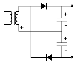
Re: Crash and burnt coilgun
Dalus, Sat Jul 07 2007, 04:46PM
The voltage doubler circuit is ok to double the charging voltage, but the diodes should be rated twice the input voltage. The caps need to be about 4.7 nf because they'll get charged en discharged rather quickly by the high operating frequency.
Dalus, Sat Jul 07 2007, 04:46PM
The voltage doubler circuit is ok to double the charging voltage, but the diodes should be rated twice the input voltage. The caps need to be about 4.7 nf because they'll get charged en discharged rather quickly by the high operating frequency.
Re: Crash and burnt coilgun
Sulaiman, Sat Jul 07 2007, 06:56PM
Just looked in on this thread, sorry for the late reply.
IF you parallel the outputs of camera flash chargers you CANNOT series the inputs because
The -ve battery connection is also the +ve capacitor connection
The net result will be to put the entire 12V (or whatever) across ONE charger ... POOF !!
Print this page