
DRSSTC
Bennem, Tue Jul 03 2007, 11:22PMHi Folks,
Due to this years wet summer we're having here in the UK,
I decided to use some time on making another DRSSTC.
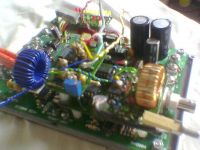
About two years ago, i purchased one of Dan McCauleys
Advanced controller boards, allthough i populated it with
components, i never got round to using it.
As it was designed for secondary feedback, i decided to
upgrade it to primary feedback and added sync shut off,
over current detection, a bargraph peak current readout
and 'set current' bar graph readout.
I have a quick question,
I read that some guys have used caps from their bus lines
to ground on their coils,
what is the reason for this?
Is it something to do with draining RF currents when subjected
to primary to secondary sparks?
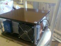
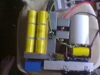
Sorry about the poor quality pics....they were taken with a phone
camera.
cheers,
Mel.
Re: DRSSTC
Part Scavenger, Tue Jul 03 2007, 11:34PM
Looking good as usual Mel!!!
Part Scavenger, Tue Jul 03 2007, 11:34PM
Looking good as usual Mel!!!
Re: DRSSTC
Bennem, Thu Jul 05 2007, 06:03AM
Cheers GB !
It may look ok....but i still have to test it on a coil....
Any ideas as to the cap question?
I read somewhere about Firkrags DRSSTC and him having
sparks appearing on his bridge, and by putting caps from
his bus lines to ground cured this.
Is this the reason folks put caps from their bus lines to ground?
Bennem, Thu Jul 05 2007, 06:03AM
Cheers GB !
It may look ok....but i still have to test it on a coil....

Any ideas as to the cap question?
I read somewhere about Firkrags DRSSTC and him having
sparks appearing on his bridge, and by putting caps from
his bus lines to ground cured this.
Is this the reason folks put caps from their bus lines to ground?
Re: DRSSTC
Steve Conner, Thu Jul 05 2007, 03:23PM
Yes, the caps are to drain away any dangerous common-mode RF voltages, that might otherwise make your gate drive transformer break down and let the smoke out big-time.
I use a single ceramic disc cap between the DC bus negative, and the mains earth. I also connect the ground rail of the driver circuitry to that same mains earth.
Re: DRSSTC
Marko, Thu Jul 05 2007, 03:56PM
God, I've just laughed out my ass after reading steve's signature.
The caps *did not* completely stop the arcing on my bridge. Much less than before, but it still occurs at ground strikes at only 60V input. I mothballed the coil for a while because of that.
This is crazy considering low RF impedance I created between two points, it still arcs over.
I now believe my single-point grounding is bad. Since I have nothing else available the secondary ground ends stuck on neutral wire wich has quite high RF impedance. Still, it doesn't explain the problem too well.
(this is all with isolation transformer. I don't know how will it behave if ran directly from mains).
Marko, Thu Jul 05 2007, 03:56PM
God, I've just laughed out my ass after reading steve's signature.
I read somewhere about Firkrags DRSSTC and him having
sparks appearing on his bridge, and by putting caps from
his bus lines to ground cured this.
Is this the reason folks put caps from their bus lines to ground?
The caps *did not* completely stop the arcing on my bridge. Much less than before, but it still occurs at ground strikes at only 60V input. I mothballed the coil for a while because of that.
This is crazy considering low RF impedance I created between two points, it still arcs over.
I now believe my single-point grounding is bad. Since I have nothing else available the secondary ground ends stuck on neutral wire wich has quite high RF impedance. Still, it doesn't explain the problem too well.
(this is all with isolation transformer. I don't know how will it behave if ran directly from mains).
Re: DRSSTC
Bennem, Thu Jul 05 2007, 05:10PM
Thanks for the replies!
I'll add something like a 1000pf cap from my neg bus rail
to mains earth.....
Bennem, Thu Jul 05 2007, 05:10PM
Thanks for the replies!
I'll add something like a 1000pf cap from my neg bus rail
to mains earth.....

Re: DRSSTC
Bennem, Sun Jul 08 2007, 03:53PM
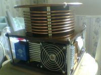
Today i made my primary coil and strike ring.
I have another question....if thats ok?
What do you guys use to connect to your primary coil?
on my last mini DRSSTC i used an ordinary fuse clip
from a mains plug and it got very hot!
Bennem, Sun Jul 08 2007, 03:53PM
Today i made my primary coil and strike ring.
I have another question....if thats ok?
What do you guys use to connect to your primary coil?
on my last mini DRSSTC i used an ordinary fuse clip
from a mains plug and it got very hot!

Re: DRSSTC
Tom540, Mon Jul 09 2007, 02:12AM
Wow that looks awesome. very clean.
Tom540, Mon Jul 09 2007, 02:12AM
Wow that looks awesome. very clean.
Re: DRSSTC
thedatastream, Mon Jul 09 2007, 07:27AM
Mel,
I used some copper earthing straps from B+Q designed for 15mm pipe. I hammered them flat and then re-bent them around an M8 rod so that they would clamp to the 8mm microbore pipe that I used for my primary.
James
thedatastream, Mon Jul 09 2007, 07:27AM
Mel,
I used some copper earthing straps from B+Q designed for 15mm pipe. I hammered them flat and then re-bent them around an M8 rod so that they would clamp to the 8mm microbore pipe that I used for my primary.
James
Re: DRSSTC
ArcLight, Mon Jul 09 2007, 07:36PM
I couldn't get a fuse holder to work properly either. And a clamp that I fashioned with a set-screw either didn't connect well or crushed the tubing.
For general coil use (MMC, gap, etc.) I purchased a 6†by 10' roll of copper flashing (USD $23) at a home improvement store. Using heavy-duty scissors I cut a strip about 5/8†wide by 1 3/4" long. Then drilled two holes (whatever size that's appropriate for a #10 screw) 1 3/16†apart. The piece was then wrapped around a form that was slightly smaller in diameter than the primary tubing and the screw installed. I then used needle-nose pliers to make the copper perfectly fit the form. After forming, the piece was finished on a belt sander to remove burrs, sharp corners, etc. The piece was then installed on the primary and secured with a couple of washers and a 1/2†#10 brass screw. It's not as convenient to move when tuning, but it has never failed to function properly.
After I wrote my response, I actually read thedatastream's post. Basically, I'm saying the same thing, but with more words.
Regards, ArcLight
ArcLight, Mon Jul 09 2007, 07:36PM
I couldn't get a fuse holder to work properly either. And a clamp that I fashioned with a set-screw either didn't connect well or crushed the tubing.
For general coil use (MMC, gap, etc.) I purchased a 6†by 10' roll of copper flashing (USD $23) at a home improvement store. Using heavy-duty scissors I cut a strip about 5/8†wide by 1 3/4" long. Then drilled two holes (whatever size that's appropriate for a #10 screw) 1 3/16†apart. The piece was then wrapped around a form that was slightly smaller in diameter than the primary tubing and the screw installed. I then used needle-nose pliers to make the copper perfectly fit the form. After forming, the piece was finished on a belt sander to remove burrs, sharp corners, etc. The piece was then installed on the primary and secured with a couple of washers and a 1/2†#10 brass screw. It's not as convenient to move when tuning, but it has never failed to function properly.
After I wrote my response, I actually read thedatastream's post. Basically, I'm saying the same thing, but with more words.

Regards, ArcLight
Re: DRSSTC
Bennem, Mon Jul 09 2007, 08:39PM
Cheers guys!
Looks like a trip to my local B&Q store tomorrow
and get some copper earthing straps.
Bennem, Mon Jul 09 2007, 08:39PM
Cheers guys!
Looks like a trip to my local B&Q store tomorrow
and get some copper earthing straps.
Re: DRSSTC
thedatastream, Tue Jul 10 2007, 06:58AM
Yes, go and pay your dues at the big orange temple! I spend so much there at the moment I should get a trade account...
As a side note, I bought two straps, one for the base and one for the tuning point
James
thedatastream, Tue Jul 10 2007, 06:58AM
Bennem wrote ...
...Looks like a trip to my local B&Q store tomorrow...
...Looks like a trip to my local B&Q store tomorrow...
Yes, go and pay your dues at the big orange temple! I spend so much there at the moment I should get a trade account...
As a side note, I bought two straps, one for the base and one for the tuning point
James
Re: DRSSTC
Bennem, Tue Jul 10 2007, 04:40PM
Yes james....and that orange temple takes a third of my wages!......lol
Right...got some today, i will do as you suggested
and flatten the strap and re-mould it to the diameter of
my primary tubeing.
Bennem, Tue Jul 10 2007, 04:40PM
Yes james....and that orange temple takes a third of my wages!......lol
Right...got some today, i will do as you suggested
and flatten the strap and re-mould it to the diameter of
my primary tubeing.
Re: DRSSTC
Bennem, Fri Jul 20 2007, 07:39AM
Hi Folks,
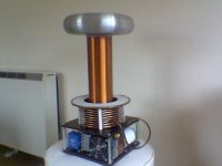
Just finished this DRSSTC by mounting the topload.
Now for some tuning with low volts.
I must learn how to tune these properly instead
of just tuning for largest output spark at low voltage on the bus.
I always seem to build them first and do tests later instead of
what i should do, is to do tests with its guts out.....lol
JAVA TC estimates my tuning point to be 4.65 for approx 200Khz
so for a starting point i've set it to this recomendation.
Is this how you guys start with tuning?
(on reflection, i should have put this thread in the 'projects section'
sorry moderators! )
Cheers,
Mel.

Re: DRSSTC
thedatastream, Fri Jul 20 2007, 09:24AM
Mel,
Looking very tidy indeed! :)
I've seen tuning info on this forum in the past - try searching for tuning on the Tesla coil board
This result looks like a possible help

James
thedatastream, Fri Jul 20 2007, 09:24AM
Mel,
Looking very tidy indeed! :)
I've seen tuning info on this forum in the past - try searching for tuning on the Tesla coil board
This result looks like a possible help

James
Re: DRSSTC
Bennem, Fri Jul 20 2007, 11:45AM
Cheers James!
lots to read up on when i get home from work,
i don't quite think my boss will appreciate if i start now......lol
Bennem, Fri Jul 20 2007, 11:45AM
Cheers James!
lots to read up on when i get home from work,
i don't quite think my boss will appreciate if i start now......lol
Re: DRSSTC
Coronafix, Fri Jul 20 2007, 12:56PM
Beautiful, just beautiful.
Coronafix, Fri Jul 20 2007, 12:56PM
Beautiful, just beautiful.
Re: DRSSTC
Tom540, Sat Jul 21 2007, 08:18PM
Damn it looks really good so far. Can't wait to see it working.
Tom540, Sat Jul 21 2007, 08:18PM
Damn it looks really good so far. Can't wait to see it working.
Re: DRSSTC
Bennem, Sun Jul 22 2007, 05:30PM
Well...Today i decided to try and fire this thing up,
i applied 30 volts to my bus line.
Not a sausage!
i reversed my primary feedback connections,
still no 'rasp' of any spark output.
I dismantled everything only to find that my primary feedback input
was short circuiting to earth when the lid of the box was on.
Now with 30 volts on the bus, my primary tapped at 4.5 turns and my intterupter
set at 100us and 100Hz....i get a 6 inch spark to a grounded rod.
still needs tuning.
As i live in an appartment block, my neighbors below me came a knocking on
my door saying that everytime they heard a 'buzzing' noise from my flat,
their digital tv picture would 'freeze'.....and demanded that i stop
whatever i was doing immediately!........lol
Did Dr Frankenstein have this problem?...i think not!.....lol
Damn.....i will have to take it to work with me next week
to see its full potential
Its just as well i work in a large open spaced workshop!
cheers
Mel.
Re: DRSSTC
colin heath, Sun Jul 22 2007, 08:05PM
Hi Mel,
Coils looking really nice. If your coils are anything like mine it won't be the output of the coil causing the problem. I found with a filter on the mains and using SY mains cable (braided) with one end grounded this problem all but dissapeared.
although saying that what earth are you using
Cheers
Colin
Re: DRSSTC
Bennem, Sun Jul 22 2007, 09:22PM
Hi Colin,
I have no mains filter on my coil at present,
but...food for thought.
For RF ground and just for low voltage testing, i'm using mains earth.
since my last two coils are small DRSSTC's....i used mains ground,
i also ground my electronics to the same earth.
but this 12 x 4 inch secondary is the largest yet built
by myself. so possibly a better earth is called for?
I hope to moving into a house early next year,
so.....a bigger coil is calling!!.......lol
Mel.
Re: DRSSTC
Bennem, Sun Jul 29 2007, 12:12PM
Arrgh!!...seems my peak current bar graph is not working,but
the 'Set Current' part of the readout is working fine,
i figure that the wire from the current feedback part has come adrift to the bar graph read out.My over current detection is working ok and at the moment is set for 200 amps
(two LEDS on the bar graph) due to the configaration /burden resistors, my current feedback is 1 volt =100amp.
With my intterupter set to 100us at 100 hz and 50% on my variac,
i'm getting 21 inch arcs to a grounded rod before my over current kicks in.
Dose this sound ok to you guys for this amount of power?
Obviosly i will have to experiment on tuning.....but this is as as far
as i have got so far.
Cheers,
Mel.
Re: DRSSTC
Bennem, Thu Sept 06 2007, 06:34PM
Due to heavy work load, i haven't had chance to mess around
with this DRSSTC.
Today however, i powered it up to 60% on the variac with an
interrupter setting of 80HZ and 100uS,
i then nervously hid by a wall and turned it on.....lol
its sparks hit a grounded rod 30inches away a few times,
i still have to experiment with tuning and set the over current
to trip at a higher level.
I'm hoping to get around 36 inch sparks eventually.
Here's a video link to it.

Bennem, Thu Sept 06 2007, 06:34PM
Due to heavy work load, i haven't had chance to mess around
with this DRSSTC.
Today however, i powered it up to 60% on the variac with an
interrupter setting of 80HZ and 100uS,
i then nervously hid by a wall and turned it on.....lol
its sparks hit a grounded rod 30inches away a few times,
i still have to experiment with tuning and set the over current
to trip at a higher level.
I'm hoping to get around 36 inch sparks eventually.

Here's a video link to it.

Re: DRSSTC
thedatastream, Thu Sept 06 2007, 08:58PM
Nice one Mel, I'm not jealous or owt... ;)
thedatastream, Thu Sept 06 2007, 08:58PM
Nice one Mel, I'm not jealous or owt... ;)
Print this page