sub-optimal 6 in. coil performance
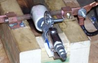
jameselectric, Wed Jun 20 2007, 10:29PMokay guys I am beating my head against the wall on this one. With my 6 in. coil at best I can only achieve 45 in. sparks. I have seen claims of 7-9 ft. with a quad pack. Here is my setup
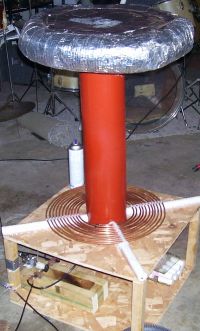
24" by 6" winding height 26 AWG
1/4 primary 11 turns
static spark gap blown and sucked via shop air and shop vac
toriod 20" by 4" roughly
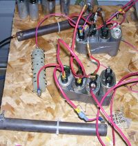
MMC 48 nf
Tapped 10th turn (works best)
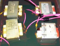
4 mots wired for 240 parallel series parallel combo
tried numerous configurations of :
1-3 doublers
1-5 caps on each side
50 ohm or 100ohm resistors
I tried at one time all of these or none of these circuits.
I have not tried a rotary gap as I don't have one.
I have also moved the toroid up and down.
The primary to secondary coupling is .200"
Any help is always appreciated
Thanks guys
Re: sub-optimal 6 in. coil performance
sparky, Thu Jun 21 2007, 12:06AM
First off how much power are you drawing from the mains VS how much power are you getting into the tank circuit? I see 3 MO caps in series on each leg of the circuit with a diode network and a resistor.... but where are the chokes?? These are very vital to any DC resonate charging system! Also your primary turns will need to be added to --- I'd say 15- then tap on turn 12. I will make a money bet that because of the OD diameter size of your primary the inductance will be to high and thus cut down on the secondary power transfer. I think tapping out further you will see at least a boost in coil performance.
Re: sub-optimal 6 in. coil performance
J. Aaron Holmes, Thu Jun 21 2007, 12:10AM
Hard to see exactly what you've got wired up there. I'm guessing 45" streamers means > 120pps on the gap, since 120pps would be 380W (assuming 8400V off your MOT stack) which translates to 33" streamers via the Freau equation, if my calc.exe skills haven't failed me.
You are using MO caps as your main capacitor? Scary. They aren't meant for pulse discharge, and may "pulse discharge" their guts all over the place on a moment's notice! Or are those your ballast, perhaps?
Generally, static gaps on MOT stack-based coils seem like a hard thing. Your lower-than-average voltage together with higher-than-average cap size plus your smallish high-frequency coil means the currents at the gap are going to be brutal. Add in the close gap spacing necessary for that lower-than-average voltage to jump and you can see why quenching is going to be tricky.
Cheers,
Aaron, N7OE
J. Aaron Holmes, Thu Jun 21 2007, 12:10AM
Hard to see exactly what you've got wired up there. I'm guessing 45" streamers means > 120pps on the gap, since 120pps would be 380W (assuming 8400V off your MOT stack) which translates to 33" streamers via the Freau equation, if my calc.exe skills haven't failed me.
You are using MO caps as your main capacitor? Scary. They aren't meant for pulse discharge, and may "pulse discharge" their guts all over the place on a moment's notice!
 Or are those your ballast, perhaps?
Generally, static gaps on MOT stack-based coils seem like a hard thing. Your lower-than-average voltage together with higher-than-average cap size plus your smallish high-frequency coil means the currents at the gap are going to be brutal. Add in the close gap spacing necessary for that lower-than-average voltage to jump and you can see why quenching is going to be tricky.
Cheers,
Aaron, N7OE
Re: sub-optimal 6 in. coil performance
jameselectric, Thu Jun 21 2007, 03:05AM
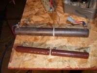
I have mot caps for ballast. I also use the resistors for chokes for the charging circuit. Can I do this or do I need to use mots for the chokes? I have 2 of each kind. The 2 smaller ones are 50 ohms 50 watts and the 2 large ones are 225 watts 100 ohms. I have a mmc composed of 48 1600 v caps giving me around 48 nf.
Thanks,
James
Re: sub-optimal 6 in. coil performance
sparky, Thu Jun 21 2007, 05:31AM
No, resistors are meant specifically to control RF feedback. Chokes are needed to control the current flow and are vital to getting good performance from a DC system.
sparky, Thu Jun 21 2007, 05:31AM
No, resistors are meant specifically to control RF feedback. Chokes are needed to control the current flow and are vital to getting good performance from a DC system.
Re: sub-optimal 6 in. coil performance
J. Aaron Holmes, Thu Jun 21 2007, 05:31AM
A schematic would probably help, although I'm probably the wrong one to talk about DC resonant charging. By "choke", do you mean "charging reactor"? Yes, I realize they both mean "inductor", but the latter term is more appropriate in this context since you're not trying to limit current, but rather store energy.
Using resistors for your charging reactor makes no sense to me at all. Your charging reactor would need to be several *Henries* at least. You'll be lucky to find a few mH in those wirewound resistors, I think! And then there's the whole "resistance" issue All of the charging reactors I've seen in TCs are wound on steel cores like transformers.
Cheers,
Aaron, N7OE
J. Aaron Holmes, Thu Jun 21 2007, 05:31AM
A schematic would probably help, although I'm probably the wrong one to talk about DC resonant charging. By "choke", do you mean "charging reactor"? Yes, I realize they both mean "inductor", but the latter term is more appropriate in this context since you're not trying to limit current, but rather store energy.
Using resistors for your charging reactor makes no sense to me at all. Your charging reactor would need to be several *Henries* at least. You'll be lucky to find a few mH in those wirewound resistors, I think! And then there's the whole "resistance" issue
 All of the charging reactors I've seen in TCs are wound on steel cores like transformers.
Cheers,
Aaron, N7OE
Re: sub-optimal 6 in. coil performance
jameselectric, Fri Jun 22 2007, 10:09AM
okay I have subsituted the power resistors with 4 mots for charging reactors. I shorted the primaries and ran the Hv leg through the secondary. The old mots I have actually have a ground spade on the chassis. All 4 mot-reactors are in series. This gives me much better performance. The best performance is with 1 set of doublers. I also threw in a dequeing diode to prevent backleakage. I will still continue to add more turns on the primary and work on a smoother toroid.
Re: sub-optimal 6 in. coil performance
colin heath, Fri Jun 22 2007, 07:28PM
Hi James,
With the setup you have you do not require an inductive or resistive ballast. The capacitors you have on the doubler will add a capacitive reactance which will restrict flow of current fine on it's own.
Without getting into the exact formulas the caps will give roughly the following results.
1 cap on each leg = 3kw
2 cap on each leg = 2kw
3 cap on each leg = 1kw
Obviously these are very approximate as the current will be V/Z = I So more voltage will change the figures.
The above figures are working on the MO caps being in series. The more capacitance the more current.
Cheers
Colin
Re: sub-optimal 6 in. coil performance
sparky, Fri Jun 22 2007, 10:04PM
High voltage charging reactors need to be at least 5 Henries - an MOT shorted should be around 5.5 Henries if memory serves me well. I did some measurements last night of my twin MOT stack with 1.06 uF 2500VAC rated MO caps --- with two caps (one on each leg) I was able to draw 3.6 kW with secondary voltage measuring 4880 VAC.
Print this page

