
Inside the Van de Graaff
Finn Hammer, Sun Jun 10 2007, 08:48PMHere is a Van de Graaff generator that I`ve just built:
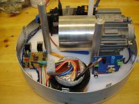
The motor is a cute little 0.12kW 2900 RPM 3-phase unit in a 56 Frame, and the pulley is 100mm dia.
The flyback is used to create the corona spray for the lower comb.
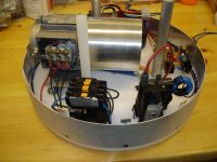
Front wiew:
Corona generator is on the green pcb.
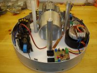
I would not have bothered you with this VDG, if it had not contained some novelty, and this is it:
The blue print contains the fiber optic components that allow the user to start the VDG by pressing a button positioned at the top of the terminal. The fiber is cut in 2 up the terminal, and a gobo connected to the on-off button allows light to pass when the button is depressed. This VDG is made specifically for hair raising duty.
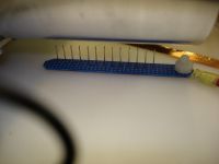
The spray and collector combs are made from stripboard and short needles:
The lower spray comb looks like this:
The top electrode is made from IKEA bowls, and the inside looks like this:
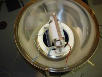
The white stuff is HDPE which I like because it is fantastic to machine.
Collector comb is conected to the top pulley, and the top spray comb is connected to the terminal. This way the belt is charged on both runs, so that it delivers double current.
The string of resistors keeps the top end from self exciting. This means that there is only output as long as the bottom spray is on. This makes it possible to remove the hands from the terminal as soon as the motor and spray is off, but while the belt is still coasting to a halt.
Here is the connection from the collector comb to the top roller:
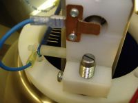
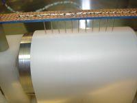
The belt is a conveyer belt from HABASIT, specifically non anti static. It is 0.7mm thick and it is 80mm wide.
Seen here with the top spray comb:
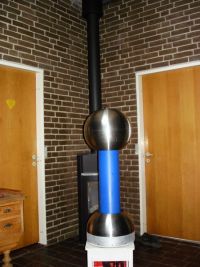
This is the finished article:
!
The generator charges with 50uA and is this enough to raise hairs?
Susanne has curly hair, like this:

Charge her up, and her hair looks like this:

Jette, on the other hand is fair haired, and charged to full potential she looks like this, on a day with 90% humidity:

Based on this, I conclude that for no questions asked hair raising, 250uA would be the way to go. Now I have a 200mm wide belt, put it on a 200mm pulley.......
That`s it, folks !
Re: Inside the Van de Graaff
Hazmatt_(The Underdog), Sun Jun 10 2007, 09:32PM
Nice Job!
Are the drive pulleys convex (raised in the center) to keep the belt centered?
I ask because a firend of mine had a terrible time with the belt walking.
Hazmatt_(The Underdog), Sun Jun 10 2007, 09:32PM
Nice Job!
Are the drive pulleys convex (raised in the center) to keep the belt centered?
I ask because a firend of mine had a terrible time with the belt walking.
Re: Inside the Van de Graaff
Finn Hammer, Sun Jun 10 2007, 09:42PM
Yes.
Both pulleys are crowned by turning a 1 degree taper on the outher quarter of the total length.
This is all it takes, and crowning should always be used.
Cheers, Finn Hammer
Finn Hammer, Sun Jun 10 2007, 09:42PM
Yes.
Both pulleys are crowned by turning a 1 degree taper on the outher quarter of the total length.
This is all it takes, and crowning should always be used.
Cheers, Finn Hammer
Re: Inside the Van de Graaff
Sulaiman, Mon Jun 11 2007, 01:40AM
Looks really good.
I have never made a VDG (and probably never will) but I am curious,
If the lower comb is positioned to spray the inside of the belt, could you omit the upper needles and just use the roller?
Sulaiman, Mon Jun 11 2007, 01:40AM
Looks really good.
I have never made a VDG (and probably never will) but I am curious,
If the lower comb is positioned to spray the inside of the belt, could you omit the upper needles and just use the roller?
Re: Inside the Van de Graaff
Ken M., Mon Jun 11 2007, 02:54AM
It charges the outside of the belt not the inside if you look at image...1,3,and 4, you'll notice that the corona spray comb would charge the outside of the belt producing an obvious charge difference between the inside and outside of the belt. I think thats covers what your asking, if not sorry for the babbling.
Re: Inside the Van de Graaff
Part Scavenger, Mon Jun 11 2007, 03:38AM
Just a thought I had about VDG's the other day if anyone cares... The ionizing brushes from laser printers would be perfect for VDG construction!
Part Scavenger, Mon Jun 11 2007, 03:38AM
Just a thought I had about VDG's the other day if anyone cares... The ionizing brushes from laser printers would be perfect for VDG construction!
Re: Inside the Van de Graaff
Finn Hammer, Mon Jun 11 2007, 01:30PM
The brushes are one part that I`d like to be able to just buy.
Do you have pctures of it, so that I can see one without tearing my printer apart?
I have no idea where to look in the printer anyway, so perhaps you could guide me there as well.
Chees, Finn Hammer
Finn Hammer, Mon Jun 11 2007, 01:30PM
Part Scavenger wrote ...
Just a thought I had about VDG's the other day if anyone cares... The ionizing brushes from laser printers would be perfect for VDG construction!
Just a thought I had about VDG's the other day if anyone cares... The ionizing brushes from laser printers would be perfect for VDG construction!
The brushes are one part that I`d like to be able to just buy.
Do you have pctures of it, so that I can see one without tearing my printer apart?
I have no idea where to look in the printer anyway, so perhaps you could guide me there as well.
Chees, Finn Hammer
Re: Inside the Van de Graaff
sparky, Mon Jun 11 2007, 02:33PM
Along the same lines as a Van De Graff - I saw a very interesting device the other day... rather than using a belt to create the static it uses a powder blown through an acrylic tube network via an air compressor to make a very decent charge. It had a 3 ft dome attached to it ---- looked like a hybrid Van De Graff to me .... maybe someone here has seen something similar before. ???
Re: Inside the Van de Graaff
DrZoidberg, Mon Jun 11 2007, 03:12PM
I have to agree. it looks really nice.
As far as I know even 5uA are enough to raise your hair.
I always wondered how much of an effect the second comb at the top has. The one that is connected to the top pulley.
I read that it doubles the current, but if I understand the working principle correctly it should only increase the current by about 30 to 50%.
Could you test that? I mean, only if the comb is easy to diconnect and reconnect.
Re: Inside the Van de Graaff
Finn Hammer, Mon Jun 11 2007, 04:31PM
When I wrote "no questions asked" hairraising what I had in mind was that the generator should be able to raise the hair of a fuzzy haired old hippie right out of the late sixties, who hasn`t had a haircut since then. Or a wash for that matter....
In principle, the system works by doubling the current. This occours when the charge density on both the ascending belt as well as the decending belt is at a maximum.
The charge density on the ascending belt is clearly at a maximum, because I can see excess charge leaving the belt at the point of tangency to the pulley.
And with only the collector comb in place, the current delivered is as expected: 32mA.
With the top spray comb in place the current is increased to 48-52mA and I have not been able to get it higher up than that.
Antonio Carlos M. de Queiroz wrote a small program called Elcal which does a fast calculation of what to expect from a VDG as well as other handy things.

Among all the silly (but funny, YMMV) things on Lateral Science you will find the standart text about Van de Graaff generators, written in 1938 by Trump, Merrill and Safford:

Cheers, Finn Hammer
Finn Hammer, Mon Jun 11 2007, 04:31PM
DrZoidberg wrote ...
I have to agree. it looks really nice.
As far as I know even 5uA are enough to raise your hair.
This depends on the kind of hair and humidity.I have to agree. it looks really nice.
As far as I know even 5uA are enough to raise your hair.
When I wrote "no questions asked" hairraising what I had in mind was that the generator should be able to raise the hair of a fuzzy haired old hippie right out of the late sixties, who hasn`t had a haircut since then. Or a wash for that matter....

DrZoidberg wrote ...
I always wondered how much of an effect the second comb at the top has. The one that is connected to the top pulley.
I read that it doubles the current, but if I understand the working principle correctly it should only increase the current by about 30 to 50%.
Could you test that? I mean, only if the comb is easy to diconnect and reconnect.
Oh yes, I have ben testing and testing this over and over.I always wondered how much of an effect the second comb at the top has. The one that is connected to the top pulley.
I read that it doubles the current, but if I understand the working principle correctly it should only increase the current by about 30 to 50%.
Could you test that? I mean, only if the comb is easy to diconnect and reconnect.
In principle, the system works by doubling the current. This occours when the charge density on both the ascending belt as well as the decending belt is at a maximum.
The charge density on the ascending belt is clearly at a maximum, because I can see excess charge leaving the belt at the point of tangency to the pulley.
And with only the collector comb in place, the current delivered is as expected: 32mA.
With the top spray comb in place the current is increased to 48-52mA and I have not been able to get it higher up than that.
Antonio Carlos M. de Queiroz wrote a small program called Elcal which does a fast calculation of what to expect from a VDG as well as other handy things.

Among all the silly (but funny, YMMV) things on Lateral Science you will find the standart text about Van de Graaff generators, written in 1938 by Trump, Merrill and Safford:

Cheers, Finn Hammer
Re: Inside the Van de Graaff
Part Scavenger, Mon Jun 11 2007, 10:02PM
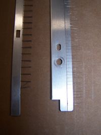
Sure! Here's a pic. They're about a foot long and you can get this pair in just about any Laser printer. I got this set from a LaserJet 5P I think. I've tried to make VDG brushes before, and yeah they're annoying.
They're not as hard as the ones you have, but I don't know if that makes much of a difference.

Re: Inside the Van de Graaff
Ken M., Tue Jun 12 2007, 12:14AM
The powder idea might not e such a good one, because if you've ever heard of grain silos exploding thats the reason why, the ground corn or wheat granules, the really fine ones are floating around and I believe a significant spark or other wise flame would ignite the power and since it'd be in an enclosed area the expanding gasses would rupture the outside as well as make a nifty flaming mushroom cloud.
Re: Inside the Van de Graaff
GreySoul, Tue Jun 12 2007, 03:27AM
You could probably use a non-flammable powder of some sort. Organic powders could ignite, sure... but what about some silica flour (SiO2), mica powder, PVC, or sodium polyacrylate?
You could also use nitrogen or CO2 as your high pressure "air" source. After an initial purge you'd run very little risk or explosion.
Or maybe a closed loop system using Sulfur hexafluoride?
...hrm.... so now I have a coil gun, a VTTC, and a VDG to make this summer.
yay me.
My Art degree at work?
-Doug
Re: Inside the Van de Graaff
Antonio, Tue Jun 12 2007, 11:21PM
A nice construction. I liked the idea of a control in the terminal to activate the machine, and also the top current doubler. I find a bit strange the 50 uA charging current. This is a lot of current for a VDG. My recently built machine is about the same size and works well in hair-rising experiments with just 5 uA. It can go to 10 uA, but the noise and vibration become inconvenient. I have made experiments with printer brushes as described. They work well, specially in doublers. There is some risk of belt contamination, depending on the kind of material used in the brushes.
Re: Inside the Van de Graaff
Finn Hammer, Wed Jun 13 2007, 05:20AM
Welcome to 4hv, Antonio
Elcal says:
Van de Graaff generator calculations
Maximum voltage: 540.0 kV
Terminal voltage: 540.0 kV
Belt length: 151.4 cm
Charging current: 32.16 µA
Terminal capacitance: 20.02 pF
Stored energy: 2.9187 J
Terminal charge: 10.8098 µC
Electrical power: 17.3668 W
Pulley rotation speed 2891.83 rpm
Charging time 0.34 s
Maximum load 16790.7 MOhmss
Does Elcal assume charge doubler?
Your terminal has a better shape, so your max voltage is likely higher than mine. I can only draw 125-- to 150mm sparks.
With proper top terminal.
Cheers, Finn Hammer
Finn Hammer, Wed Jun 13 2007, 05:20AM
Welcome to 4hv, Antonio
Antonio wrote ...
I find a bit strange the 50 uA charging current. This is a lot of current for a VDG.
Consider the driving pulley being 100mm diameter rotating at near 3000RPM, belt width 80mm.I find a bit strange the 50 uA charging current. This is a lot of current for a VDG.
Elcal says:
Van de Graaff generator calculations
Maximum voltage: 540.0 kV
Terminal voltage: 540.0 kV
Belt length: 151.4 cm
Charging current: 32.16 µA
Terminal capacitance: 20.02 pF
Stored energy: 2.9187 J
Terminal charge: 10.8098 µC
Electrical power: 17.3668 W
Pulley rotation speed 2891.83 rpm
Charging time 0.34 s
Maximum load 16790.7 MOhmss
Does Elcal assume charge doubler?
Antonio wrote ...
My recently built machine is about the same size and works well in hair-rising experiments with just 5 uA. It can go to 10 uA
My recently built machine is about the same size and works well in hair-rising experiments with just 5 uA. It can go to 10 uA
Your terminal has a better shape, so your max voltage is likely higher than mine. I can only draw 125-- to 150mm sparks.
Antonio wrote ...
but the noise and vibration become inconvenient.
I am a toolmaker. When I produced the pulley`s I made sure that all surfaces are true within 1/100mm. (0,0004"). This insures vibration and noise less operation even with the top pulley at 6000RPM. I am considering a 200mm pulley at 3000RPM in the next machine.but the noise and vibration become inconvenient.
With proper top terminal.
Cheers, Finn Hammer
Re: Inside the Van de Graaff
DrZoidberg, Wed Jun 13 2007, 05:29PM
Damn, why don't I have a machine shop?
It doesn't look like it assumes a charge doubler.
And as far as I know with your belt width and speed, 32uA is already very good.
In my opinion your machine performs pretty much perfect except for the spark length but that's because of the sharp rim at your sphere.
Re: Inside the Van de Graaff
Finn Hammer, Wed Jun 13 2007, 07:00PM
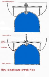
I used the technique posted by Lyonel Baum some years ago, where I cut the hole in the bowl, then draw a metal cone down into the hole with a nut and bolt. This creates a 10mm radius.
Now I realise that the hole has to come "all the way in" because there is also leakage from the charged ascending belt to the terminal. Also, the distance from the belt to terminal has to be substantial to acheive full doubling.
I set up a 110mm sphere gap:

This is the longest distance the generator will arc reliably between this diameter balls, without creating too much corona at the rim of the hole,
According to Elcal this results in a breakdown voltage of 280kV
Under these circumstances, with 32uA charging current, the charge time ought to be 0,17S
I have here a short video that shows how the machine behaves under this load:

I counted 69 discharges in 10 seconds. (If you count, you will count 57 discharges, the rest is apparently lost during processing at youtube)
That`s 0,14 S charging time, corresponding to about 40uA charging current.
Considering that the measured charging current is short circuit, meaning no corona loss at the terminal top, indicates that the corona los at 280kV is around 10uA.
Cheers, Finn Hammer
Finn Hammer, Wed Jun 13 2007, 07:00PM
DrZoidberg wrote ...
In my opinion your machine performs pretty much perfect except for the spark length but that's because of the sharp rim at your sphere.
I have been wondering how best to cave the rim in.In my opinion your machine performs pretty much perfect except for the spark length but that's because of the sharp rim at your sphere.
I used the technique posted by Lyonel Baum some years ago, where I cut the hole in the bowl, then draw a metal cone down into the hole with a nut and bolt. This creates a 10mm radius.
Now I realise that the hole has to come "all the way in" because there is also leakage from the charged ascending belt to the terminal. Also, the distance from the belt to terminal has to be substantial to acheive full doubling.
I set up a 110mm sphere gap:

This is the longest distance the generator will arc reliably between this diameter balls, without creating too much corona at the rim of the hole,
According to Elcal this results in a breakdown voltage of 280kV
Under these circumstances, with 32uA charging current, the charge time ought to be 0,17S
I have here a short video that shows how the machine behaves under this load:

I counted 69 discharges in 10 seconds. (If you count, you will count 57 discharges, the rest is apparently lost during processing at youtube)
That`s 0,14 S charging time, corresponding to about 40uA charging current.
Considering that the measured charging current is short circuit, meaning no corona loss at the terminal top, indicates that the corona los at 280kV is around 10uA.
Cheers, Finn Hammer
Re: Inside the Van de Graaff
Antonio, Thu Jun 14 2007, 01:42AM
Antonio, Thu Jun 14 2007, 01:42AM
Finn Hammer wrote ...
Does Elcal assume charge doubler?
No.Does Elcal assume charge doubler?
Finn Hammer wrote ...
Your terminal has a better shape, so your max voltage is likely higher than mine. I can only draw 125-- to 150mm sparks.
This depends on the polarity of the terminal and on the radius of curvature of the "target" too. With a negative terminal it's easy to draw long sparks to a small ball. I can obtain 30 cm with that terminal and a 2.5 cm ball. With a positive terminal I get just corona at more than ~3 cm. With a large ball the distance increases. Between two identical terminals I can obtain no more than what you obtain. I didn't measure the frequency of the sparks. Will try. Something strange with a negative terminal and a small grounded target is that most of the sparks are faint, barely visible, but some are stronger and clearly visible.Your terminal has a better shape, so your max voltage is likely higher than mine. I can only draw 125-- to 150mm sparks.
Finn Hammer wrote ...
I am a toolmaker. When I produced the pulley`s I made sure that all surfaces are true within 1/100mm. (0,0004"). This insures vibration and noise less operation even with the top pulley at 6000RPM. I am considering a 200mm pulley at 3000RPM in the next machine.
With proper top terminal.
Ok. Good mechanics are necessary for high speed. My construction was really not specially precise. I mounted the roller above the box containing the motor, connected by pulleys and a belt with it, with the motor fixed to the bottom of the box. A perfect recipe for a lot of noise.I am a toolmaker. When I produced the pulley`s I made sure that all surfaces are true within 1/100mm. (0,0004"). This insures vibration and noise less operation even with the top pulley at 6000RPM. I am considering a 200mm pulley at 3000RPM in the next machine.
With proper top terminal.
Re: Inside the Van de Graaff
Finn Hammer, Thu Jun 14 2007, 09:08PM
During today, the performance of the generator kept dropping, at an alarming rate, untill I was down to 38uA charging.
Somethng had been rumbling in the back of my head since I read Antonios write up about his latest VDG, something about aluminum contamination of the belt.
Disassembeled, the belt did show faint traces of black ruboff from the alluminium pulleys.
I took the belt into the kitchen sink, and gave it a good scrubbing with a green abrasive sponge and dish washing detergent.
Rinsed well and dried it with a towel.
While the belt was drying, I covered the pulleys with a layer of electrical tape to keep the belt clean from alluminium traces.
Once assembled again, the generator now sports a whopping 59 uA.
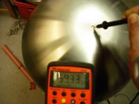
During the weekend, a Freu toroid is going to loose it`s life and become part of a hopefully perfect bottom end of the top electrode. Interesting if I can manage to hit the 64 uA which will indicate that the doubler works 100%.
I will also cover the pulleys with shrink wrap.
That learning curve is getting flatter
Cheers, Finn Hammer
Finn Hammer, Thu Jun 14 2007, 09:08PM
During today, the performance of the generator kept dropping, at an alarming rate, untill I was down to 38uA charging.
Somethng had been rumbling in the back of my head since I read Antonios write up about his latest VDG, something about aluminum contamination of the belt.
Disassembeled, the belt did show faint traces of black ruboff from the alluminium pulleys.
I took the belt into the kitchen sink, and gave it a good scrubbing with a green abrasive sponge and dish washing detergent.
Rinsed well and dried it with a towel.
While the belt was drying, I covered the pulleys with a layer of electrical tape to keep the belt clean from alluminium traces.
Once assembled again, the generator now sports a whopping 59 uA.

During the weekend, a Freu toroid is going to loose it`s life and become part of a hopefully perfect bottom end of the top electrode. Interesting if I can manage to hit the 64 uA which will indicate that the doubler works 100%.
I will also cover the pulleys with shrink wrap.
That learning curve is getting flatter
Cheers, Finn Hammer
Re: Inside the Van de Graaff
Steve Conner, Fri Jun 15 2007, 09:14AM
Good luck shrinking that shrink wrap evenly to within 0.01mm! Your generator looks awesome, BTW.
Steve Conner, Fri Jun 15 2007, 09:14AM
Good luck shrinking that shrink wrap evenly to within 0.01mm!
 Your generator looks awesome, BTW.
Re: Inside the Van de Graaff
cbfull, Fri Jun 15 2007, 02:29PM
I have to say, 59µA is rather impressive for a generator that size. It's actually the first time I've seen anyone get above 20 with a small-ish VDG. Mine has almost a 4" belt diameter, a doubler, and the roller is 3450RPM, and the most I can get right now is around 30-35µA. I know it's working good too because there is corona and leakage everywhere, and in the dark I can see faint discharges inside the column between the up/down belt halves.
Craig
Re: Inside the Van de Graaff
Finn Hammer, Fri Jun 15 2007, 03:12PM
What material is the roller, the belt, and do you spray?
Cheers, Finn Hammer
Finn Hammer, Fri Jun 15 2007, 03:12PM
cbfull wrote ...
I have to say, 59µA is rather impressive for a generator that size.
Thanks!I have to say, 59µA is rather impressive for a generator that size.
cbfull wrote ...
Mine has almost a 4" belt diameter,
Did you mean 4" wide belt or 4" diameter roller?Mine has almost a 4" belt diameter,
What material is the roller, the belt, and do you spray?
cbfull wrote ...
a doubler, and the roller is 3450RPM, and the most I can get right now is around 30-35µA.
In order to estimate the perfect output, we need to know belt width and pulley diameter. Will you post pictures of the bottom and top details?a doubler, and the roller is 3450RPM, and the most I can get right now is around 30-35µA.
Cheers, Finn Hammer
Re: Inside the Van de Graaff
Finn Hammer, Sat Jun 16 2007, 09:04PM
After a days work, the top terminal now looks like this:
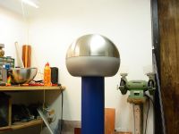
The joint btwn IKEA bowl and FREU toroid became less than ideal, so to avoid corona at that point, I had to apply an anti corrosive paint with a content of zinc. This paint managed to solve the problem.
I had hoped that the better shape of the terminal would boost the output with the missing 5 uA, and that this would reflect less leakage from the decending belt to the terminal, but this did not happen.
The maximum voltage was raised from 280kV to 320kV (measured by the 36cm Ø ball gap), but it is now limited by flashover to the base.
Cheers, Finn Hammer
Finn Hammer, Sat Jun 16 2007, 09:04PM
After a days work, the top terminal now looks like this:

The joint btwn IKEA bowl and FREU toroid became less than ideal, so to avoid corona at that point, I had to apply an anti corrosive paint with a content of zinc. This paint managed to solve the problem.
I had hoped that the better shape of the terminal would boost the output with the missing 5 uA, and that this would reflect less leakage from the decending belt to the terminal, but this did not happen.
The maximum voltage was raised from 280kV to 320kV (measured by the 36cm Ø ball gap), but it is now limited by flashover to the base.
Cheers, Finn Hammer
Re: Inside the Van de Graaff
DrZoidberg, Sun Jun 17 2007, 03:11PM
Looks really neat.
Did you also improve the shape of the base? If there is still a rim at the base that could explain the flashovers.
BTW
What materials did you use for the belt and the column?
DrZoidberg, Sun Jun 17 2007, 03:11PM
Looks really neat.
Did you also improve the shape of the base? If there is still a rim at the base that could explain the flashovers.
BTW
What materials did you use for the belt and the column?
Re: Inside the Van de Graaff
teravolt, Sun Jun 17 2007, 04:35PM
hi Finn what is the belt material and where did you get it
teravolt, Sun Jun 17 2007, 04:35PM
hi Finn what is the belt material and where did you get it
Re: Inside the Van de Graaff
Finn Hammer, Sun Jun 17 2007, 05:45PM
This is a conveyor belt from the food industry. Most of these belts are anti static, but this one is not.

The company that produces them is HABASIT

and the factory code for this particular one is F-2EQWT
The nice thing is that I specify length and width, then they weld it together, with a really nice, long finger joint.
It costs 40USD which I think is more than fair. It is washable, doesn`t stretch and is capable of running at high speeds. I don`t know how it stands up to corona, ozone and all that.
The column is made from HDPE. This is a piece from the local water supply.Therefore the nice blue.
I did not make the base like the top electrode, although I should, and this does contribute to the tendency to flashover. However, the column is only 500mm or 20" and this is also a major reason.
Cheers, Finn Hammer
Finn Hammer, Sun Jun 17 2007, 05:45PM
DrZoidberg wrote ...
Looks really neat.
Did you also improve the shape of the base? If there is still a rim at the base that could explain the flashovers.
BTW
What materials did you use for the belt and the column?
Looks really neat.
Did you also improve the shape of the base? If there is still a rim at the base that could explain the flashovers.
BTW
What materials did you use for the belt and the column?
teravolt wrote ...
hi Finn what is the belt material and where did you get it
First the belt:hi Finn what is the belt material and where did you get it
This is a conveyor belt from the food industry. Most of these belts are anti static, but this one is not.

The company that produces them is HABASIT

and the factory code for this particular one is F-2EQWT
The nice thing is that I specify length and width, then they weld it together, with a really nice, long finger joint.
It costs 40USD which I think is more than fair. It is washable, doesn`t stretch and is capable of running at high speeds. I don`t know how it stands up to corona, ozone and all that.
The column is made from HDPE. This is a piece from the local water supply.Therefore the nice blue.
I did not make the base like the top electrode, although I should, and this does contribute to the tendency to flashover. However, the column is only 500mm or 20" and this is also a major reason.
Cheers, Finn Hammer
Re: Inside the Van de Graaff
Sulaiman, Sun Jun 17 2007, 06:58PM
Looks really great -certainly display quality.
Lovely job.
Out of curiosity,
you say the column is 500mm and it flashes over at about 320kV
that's 640V/mm, quite low I thought,
is it surface tracking?
Sulaiman, Sun Jun 17 2007, 06:58PM
Looks really great -certainly display quality.
Lovely job.
Out of curiosity,
you say the column is 500mm and it flashes over at about 320kV
that's 640V/mm, quite low I thought,
is it surface tracking?
Re: Inside the Van de Graaff
Finn Hammer, Sun Jun 17 2007, 08:55PM
I frankly don`t know if this qualifies as tracking.
Cheers, Finn Hammer
Finn Hammer, Sun Jun 17 2007, 08:55PM
Sulaiman wrote ...
Looks really great -certainly display quality.
Lovely job.
Thanks!Looks really great -certainly display quality.
Lovely job.
Sulaiman wrote ...
Out of curiosity,
you say the column is 500mm and it flashes over at about 320kV
that's 640V/mm, quite low I thought,
is it surface tracking?
I can`t say for sure. But when the spark length btwn. 360mm balls exceeds 135mm, the flashovers start. These flashes run on the surface of the column, but they don`t leave any marks.Out of curiosity,
you say the column is 500mm and it flashes over at about 320kV
that's 640V/mm, quite low I thought,
is it surface tracking?
I frankly don`t know if this qualifies as tracking.
Cheers, Finn Hammer
Re: Inside the Van de Graaff
cbfull, Mon Jun 18 2007, 03:26PM
Sorry, the way I started describing the dimensions of my VDG parts was quite vague.
My roller diameter is 2.25in, or 57.15mm
Belt width is actually 3.5in, or 89mm
Upper roller is solid aluminum, soon to be made of nylon
Lower roller is solid acrylic, no forced charging.
My goal is to get maximum results WITHOUT a HVDC sprayer.
Belt is made of nylon reinforced neoprene, ends are hand sewn together, and it is 1/16" (0.0625in or 1.6mm) thickness, which is pretty heavy. I am in the process of making a new belt out of 0.022in, or 0.56mm neoprene coated nylon so I can double the belt speed.
Present speed: 34 ft/sec or 23mph.
I should be able to get it up to 60mph maximum (this is typical for a good VDG), which would be about 2.5 times my present speed.
Craig
Re: Inside the Van de Graaff
Finn Hammer, Mon Jun 18 2007, 06:27PM
I have to thank Da. Antonio for the nice litle program Elcal, which calculates this in a jiffy.
Have you had problems with alluminium contamination on the belt?
How long is your column and how is your terminal made, how big is it?
Finn Hammer, Mon Jun 18 2007, 06:27PM
cbfull wrote ...
Sorry, the way I started describing the dimensions of my VDG parts was quite vague.
My roller diameter is 2.25in, or 57.15mm
Belt width is actually 3.5in, or 89mm
With a roller speed of 3400 RPM, the max you can get is 38uA with a doubler, so I`d say you are doing very well indeed.Sorry, the way I started describing the dimensions of my VDG parts was quite vague.
My roller diameter is 2.25in, or 57.15mm
Belt width is actually 3.5in, or 89mm
I have to thank Da. Antonio for the nice litle program Elcal, which calculates this in a jiffy.
cbfull wrote ...
Upper roller is solid aluminum, soon to be made of nylon
Lower roller is solid acrylic, no forced charging.
My goal is to get maximum results WITHOUT a HVDC sprayer.
Yeah well, to each his own. I like the sprayer, because it reduces the need for low humidity to get output.Upper roller is solid aluminum, soon to be made of nylon
Lower roller is solid acrylic, no forced charging.
My goal is to get maximum results WITHOUT a HVDC sprayer.
Have you had problems with alluminium contamination on the belt?
How long is your column and how is your terminal made, how big is it?
cbfull wrote ...
Belt is made of nylon reinforced neoprene, ends are hand sewn together, and it is 1/16" (0.0625in or 1.6mm) thickness, which is pretty heavy. I am in the process of making a new belt out of 0.022in, or 0.56mm neoprene coated nylon so I can double the belt speed.
Present speed: 34 ft/sec or 23mph.
Mine is 34 MPH at the present. The belt could go *a lot* faster, so I think it is time to introduce a belt and pulley btwn. motor and the lower roller, so that the speed can get higher. This is for the next generation.Belt is made of nylon reinforced neoprene, ends are hand sewn together, and it is 1/16" (0.0625in or 1.6mm) thickness, which is pretty heavy. I am in the process of making a new belt out of 0.022in, or 0.56mm neoprene coated nylon so I can double the belt speed.
Present speed: 34 ft/sec or 23mph.
cbfull wrote ...
I should be able to get it up to 60mph maximum (this is typical for a good VDG), which would be about 2.5 times my present speed.
Craig
I should be able to get it up to 60mph maximum (this is typical for a good VDG), which would be about 2.5 times my present speed.
Craig
Re: Inside the Van de Graaff
cbfull, Tue Jun 19 2007, 12:19PM
Thanks for the comments on my VDG design. Unfortunately I am in the process of trying to get my basement finished so I can have a workspace.
I can tell you that my column is approx 40 inches long, 5 inches diameter acrylic. It was a lucky find and was given to me for free. The terminal is a 12" diameter heavy gauge aluminum sphere, halves are taped, not joined. The thickness of the aluminum basically prevents me from turning in the lower edge to try and reduce the leakage at this point, but I have another SST 14" terminal on standby that I will also be working on.
I guess I have been lucky with the aluminum roller. I have never had a problem with the metal contaminating the belt, as far as I know.
I'll have to get some pictures of it soon.
Thanks Hammer.
Re: Inside the Van de Graaff
Finn Hammer, Tue Jun 19 2007, 07:07PM
Today I did something fun!
Almost as fun as simulating a circuit in Spice. You know the thrill of trying out a circuit you could only dream about, certainly not build overnight.
I pulled out the frequency inverter drive, to increase the RPM on the motor.
At 120Hz, 7200 rpm, the contactor started to make non-standard noises, so that`s where I stopped it.
At that time I had 135uA on the clock.
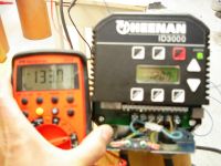
I guess this pretty much sets the standard for small VDG`s.
Pelletrons anyone?
Cheers, Finn Hammer
Finn Hammer, Tue Jun 19 2007, 07:07PM
Today I did something fun!
Almost as fun as simulating a circuit in Spice. You know the thrill of trying out a circuit you could only dream about, certainly not build overnight.
I pulled out the frequency inverter drive, to increase the RPM on the motor.
At 120Hz, 7200 rpm, the contactor started to make non-standard noises, so that`s where I stopped it.
At that time I had 135uA on the clock.

I guess this pretty much sets the standard for small VDG`s.
Pelletrons anyone?
Cheers, Finn Hammer
Re: Inside the Van de Graaff
ragnar, Wed Jun 20 2007, 03:03AM
That's an oh-so-subtle "1337", Finn hehe
hehe
ragnar, Wed Jun 20 2007, 03:03AM
That's an oh-so-subtle "1337", Finn
 hehe
heheRe: Inside the Van de Graaff
Antonio, Thu Jun 21 2007, 11:44PM
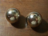
It seems possible to make a pelletron using as chain a string of beads, alternating conductive and insulating beads in an a strong insulating string. I can easily find chrome-plated plastic beads with 2 cm of diameter that look interesting for a demonstration machine.
For more current, parallel strings can be used.

Re: Inside the Van de Graaff
Finn Hammer, Sat Jun 23 2007, 01:25PM
I wonder how is it possible to determine the current that can be delivered from a chain of a given dimension, and speed.
At pelletron.com they claim up to 200uA per chain.

The chains that I have seen, I would estimate to be only 20 mm in diametre, but perhaps bigger chains are available on the big machines.
Fermilab’s Pelletron

Has these information:
************************************************* ******
Table T1: Charging System Parameters
Motor revolution frequency: 19.3 Rev/sec
Motor Power: 5.6 kW
Actual Load: ~0.5 kW
Nominal chain speed: 18.5 m/sec
Chain central diameter around sheaves: 30.5 cm
Distance between sheave centers: 3.68 m
Chain revolution frequency: 1.8 Hz
Length of a single pellet: 32 mm
Gap between pellets: 5.3 mm
Maximum voltage of charging PS: 60 kV
Charging efficiency in good condition: 7.3 µA/kV
(based on two chains with charging at the ground and at the terminal)
************************************************* *********
60kV*7.3 = 438uA/2 = 219uA per chain.
But 60kV is very high for a hobby system.
The distance btwn pellets is also surprisingly short. I assume that the chain has to be very long due to this...

And the speed can be increased...
Cheers, Finn Hammer
Finn Hammer, Sat Jun 23 2007, 01:25PM
Antonio wrote ...
It seems possible to make a pelletron using as chain a string of beads, alternating conductive and insulating beads in a strong insulating string. I can easily find chrome-plated plastic beads with 2 cm of diameter that look interesting for a demonstration machine.
Building a pelletron would be interesting.It seems possible to make a pelletron using as chain a string of beads, alternating conductive and insulating beads in a strong insulating string. I can easily find chrome-plated plastic beads with 2 cm of diameter that look interesting for a demonstration machine.
I wonder how is it possible to determine the current that can be delivered from a chain of a given dimension, and speed.
At pelletron.com they claim up to 200uA per chain.

The chains that I have seen, I would estimate to be only 20 mm in diametre, but perhaps bigger chains are available on the big machines.
Fermilab’s Pelletron

Has these information:
************************************************* ******
Table T1: Charging System Parameters
Motor revolution frequency: 19.3 Rev/sec
Motor Power: 5.6 kW
Actual Load: ~0.5 kW
Nominal chain speed: 18.5 m/sec
Chain central diameter around sheaves: 30.5 cm
Distance between sheave centers: 3.68 m
Chain revolution frequency: 1.8 Hz
Length of a single pellet: 32 mm
Gap between pellets: 5.3 mm
Maximum voltage of charging PS: 60 kV
Charging efficiency in good condition: 7.3 µA/kV
(based on two chains with charging at the ground and at the terminal)
************************************************* *********
60kV*7.3 = 438uA/2 = 219uA per chain.
But 60kV is very high for a hobby system.
The distance btwn pellets is also surprisingly short. I assume that the chain has to be very long due to this...

Antonio wrote ...
For more current, parallel strings can be used.
For more current, parallel strings can be used.
And the speed can be increased...

Cheers, Finn Hammer
Re: Inside the Van de Graaff
Antonio, Sun Jun 24 2007, 11:19PM
These high currents are surely due to operation in a pressurized tank. The charging current
can be estimated as i=NfAp, where
N=number of pellets
f=chain rotation frequency
A=pellet external area
p=maximum charge density (26.55 uC/m^2 in air)
This assumes that the pellets leave the lower pulley with one half of the maximum charge
density and that there is a current doubler at the top pulley.
With the data that you list, and assuming a pellet diameter equal to the length, I
get 34.4 uA.
Antonio, Sun Jun 24 2007, 11:19PM
Finn Hammer wrote ...
I wonder how is it possible to determine the current that can be delivered from a chain of a given dimension, and speed.
At pelletron.com they claim up to 200uA per chain.
60kV*7.3 = 438uA/2 = 219uA per chain.
But 60kV is very high for a hobby system.
I wonder how is it possible to determine the current that can be delivered from a chain of a given dimension, and speed.
At pelletron.com they claim up to 200uA per chain.
60kV*7.3 = 438uA/2 = 219uA per chain.
But 60kV is very high for a hobby system.
These high currents are surely due to operation in a pressurized tank. The charging current
can be estimated as i=NfAp, where
N=number of pellets
f=chain rotation frequency
A=pellet external area
p=maximum charge density (26.55 uC/m^2 in air)
This assumes that the pellets leave the lower pulley with one half of the maximum charge
density and that there is a current doubler at the top pulley.
With the data that you list, and assuming a pellet diameter equal to the length, I
get 34.4 uA.
Re: Inside the Van de Graaff
Finn Hammer, Mon Jun 25 2007, 06:02PM
In that case, I am out.
I am a performance freak, and would rather build a 60cm toploaded machine with 300uA charging ability in atmospheric pressure with a polyurethane belt.
Cheers, Finn Hammer
Finn Hammer, Mon Jun 25 2007, 06:02PM
Antonio wrote ...
These high currents are surely due to operation in a pressurized tank.
With the data that you list, and assuming a pellet diameter equal to the length, I
get 34.4 uA.
These high currents are surely due to operation in a pressurized tank.
With the data that you list, and assuming a pellet diameter equal to the length, I
get 34.4 uA.
In that case, I am out.
I am a performance freak, and would rather build a 60cm toploaded machine with 300uA charging ability in atmospheric pressure with a polyurethane belt.
Cheers, Finn Hammer
Re: Inside the Van de Graaff
Finn Hammer, Thu Jun 28 2007, 08:48AM
All,
Just to wrap this up.
Great fun was had when I delivered the VDG to it`s proper home, The Danish Electricity Museum.
Seen here is a guest checking it out.

With this machine, the guests can raise hair without getting shocked. They have to touch the terminal to get the belt running, so the approach to the machine is without agony. The machine stops charging as soon as they release the button, so they can get away from the machine without getting chocked either.
Cheers, Finn Hammer
Finn Hammer, Thu Jun 28 2007, 08:48AM
All,
Just to wrap this up.
Great fun was had when I delivered the VDG to it`s proper home, The Danish Electricity Museum.
Seen here is a guest checking it out.

With this machine, the guests can raise hair without getting shocked. They have to touch the terminal to get the belt running, so the approach to the machine is without agony. The machine stops charging as soon as they release the button, so they can get away from the machine without getting chocked either.
Cheers, Finn Hammer
Re: Inside the Van de Graaff
Lyonel Baum, Thu Jul 12 2007, 03:45PM
Hi all ,
More to come on embossing Vdg dome ...
Lyonel Baum
Lyonel Baum, Thu Jul 12 2007, 03:45PM
Hi all ,
More to come on embossing Vdg dome ...
Lyonel Baum
Re: Inside the Van de Graaff
Lyonel Baum, Thu Jul 12 2007, 05:41PM
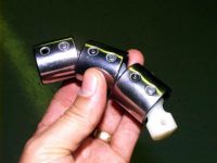
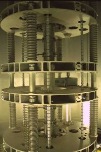
Here are a picture of 3 pellets and a picture of a 2 chains NEC Pelletron
Lyonel Baum, Thu Jul 12 2007, 05:41PM
Finn Hammer wrote ...

And the speed can be increased...
Cheers, Finn Hammer
Antonio wrote ...
It seems possible to make a pelletron using as chain a string of beads, alternating conductive and insulating beads in a strong insulating string. I can easily find chrome-plated plastic beads with 2 cm of diameter that look interesting for a demonstration machine.
The distance btwn pellets is also surprisingly short. I assume that the chain has to be very long due to this...It seems possible to make a pelletron using as chain a string of beads, alternating conductive and insulating beads in a strong insulating string. I can easily find chrome-plated plastic beads with 2 cm of diameter that look interesting for a demonstration machine.

Antonio wrote ...
For more current, parallel strings can be used.
For more current, parallel strings can be used.
And the speed can be increased...

Cheers, Finn Hammer
Here are a picture of 3 pellets and a picture of a 2 chains NEC Pelletron


Re: Inside the Van de Graaff
Lyonel Baum, Thu Jul 12 2007, 05:56PM
Lyonel Baum, Thu Jul 12 2007, 05:56PM
Lyonel Baum wrote ...
Hi all ,
More to come on embossing Vdg dome ...
Lyonel Baum
Hi all ,
More to come on embossing Vdg dome ...
Lyonel Baum

Re: Inside the Van de Graaff
Lyonel Baum, Thu Jul 12 2007, 06:30PM
Take a look on this Tandem in Heildelberg ( Deutschland ) : 3 chains Pelletron
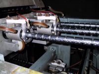
Lyonel Baum, Thu Jul 12 2007, 06:30PM
Antonio wrote ...
It seems possible to make a pelletron using as chain a string of beads, alternating conductive and insulating beads in an a strong insulating string. I can easily find chrome-plated plastic beads with 2 cm of diameter that look interesting for a demonstration machine.
For more current, parallel strings can be used.

Take a look on this Tandem in Heildelberg ( Deutschland ) : 3 chains Pelletron

Re: Inside the Van de Graaff
Finn Hammer, Thu Jul 12 2007, 07:40PM
Lyonell,
Welcome to 4hv and this thread.
Your input is highly valued and your pictures of pelletrons are invaluable.
Thanks!
Cheers, Finn Hammer
Finn Hammer, Thu Jul 12 2007, 07:40PM
Lyonell,
Welcome to 4hv and this thread.
Your input is highly valued and your pictures of pelletrons are invaluable.
Thanks!
Cheers, Finn Hammer
Re: Inside the Van de Graaff
Lyonel Baum, Fri Jul 13 2007, 02:03PM
Most air-insulated VDGRF's require only 7 kV DC at 1 mA to achieve full charge on a belt width of 1 inch through 20 inches.
Be absolutely sure that the spray screen is equal to or less than 80% of the belt width. This prevents charge from "leaking" at the corners of the screen directly to the metal pulley. Short the HV terminal to ground and observe this in a very dark room --- you should see a completely uniform blue corona across the entire belt --- and not just corona spray at the edge of the screen to the pulley (poor performance).
Re: Inside the Van de Graaff
johnf, Mon Jul 16 2007, 02:06AM
An Aside for you all
pelletrons will give much smaller current to terminal than a VDG.
Our 6Mv tandem VDG has been converted to a pelletron (2chains) and all the resistors down the acceleration tube had to be changed upward by a factor of five so that the machine can reach a bit more than 6Mv.
the reason for he change is that peletrons have much lower ripple (in the terminal volts) the VDG's.
before conversion terminal ripple @ belt speed was around 60kV, now with the peletron it is 1kV or less
Re: Inside the Van de Graaff
Finn Hammer, Mon Jul 16 2007, 06:24AM
Interesting, Do you know which material was used for the belt?
I am surprised to hear that the ripple was 1%. The Round Hill generator built in 1934-36 had a regulation of 0.1%.
This superior figure was achieved by a combination of attention to details in the belt and the charging system.
I would have thought that these results were bettered by a contemporary belt system.
Cheers, Finn Hammer
Finn Hammer, Mon Jul 16 2007, 06:24AM
johnf wrote ...
before conversion terminal ripple @ belt speed was around 60kV, now with the peletron it is 1kV or less
before conversion terminal ripple @ belt speed was around 60kV, now with the peletron it is 1kV or less
Interesting, Do you know which material was used for the belt?
I am surprised to hear that the ripple was 1%. The Round Hill generator built in 1934-36 had a regulation of 0.1%.
This superior figure was achieved by a combination of attention to details in the belt and the charging system.
I would have thought that these results were bettered by a contemporary belt system.
Cheers, Finn Hammer
Re: Inside the Van de Graaff
johnf, Tue Jul 17 2007, 09:23AM
Finn
Figures quoted are before applying GVM feedback and the unit is an EN tandem (Van Der Graaf Corp)
Belt condition was the major reason for change. There was a large excursion in terminal volts at the belt join as it went round.
The tandem is used for C14 dating with ratios of C12, C13, C14 being taken from samples with 5mg of carbon in the form of graphite.
The system is occasionly used for high energy implantation last week being an example with a silver beam @ 65MV ie silver atoms @ 10+ charge
the carbon foils didn't last long with 6nA on target longest implantation = 60 minutes
BTW i looked at the terminal volt deviation today under GVM control and the external derippler and terminal volts held to within + - 10 volts @ 5,250,000 volts for the ten minutes i was in the control room
To get an idea on what I /we do
I spend half my time between Isoscan and the ion beam analysis lab
johnf, Tue Jul 17 2007, 09:23AM
Finn
Figures quoted are before applying GVM feedback and the unit is an EN tandem (Van Der Graaf Corp)
Belt condition was the major reason for change. There was a large excursion in terminal volts at the belt join as it went round.
The tandem is used for C14 dating with ratios of C12, C13, C14 being taken from samples with 5mg of carbon in the form of graphite.
The system is occasionly used for high energy implantation last week being an example with a silver beam @ 65MV ie silver atoms @ 10+ charge
the carbon foils didn't last long with 6nA on target longest implantation = 60 minutes
BTW i looked at the terminal volt deviation today under GVM control and the external derippler and terminal volts held to within + - 10 volts @ 5,250,000 volts for the ten minutes i was in the control room
To get an idea on what I /we do

I spend half my time between Isoscan and the ion beam analysis lab
Re: Inside the Van de Graaff
Lyonel Baum, Mon Jul 23 2007, 09:04AM
One of the most curious modification of the Van de Graff generator had been conceived around 1936 in France by Marcel Pauthenier and all. In fact, they proposed to use a flow of charged dust particles circulating in a closed insulating pipe instead of the classical belt of the original apparatus. The dust was composed of glass spheres of a few microns in diameter. A blower produced a 60 in.p.s flow of these particles in the loop-pipe. For charging the dust there was a 'ionizer', which was composed by several wires parallel to the pipe. The wires were negatively charged (12,000 volts) by a kenotron rectifier and the electric fields of the wires ionized the gas molecules. The positive ions were immediately attracted by the wires, while negative ones were repelled in the direction of the walls of the pipe and charged the dust particles. Great care had to be taken for adjusting the various parameters (diameter and speed of the particles, voltage of the wire, diameter of the ionizing tube) so that the dust did not precipitate on the wall of the tube but could continue its journey after having been charged. At the top bend of the pipe the charged dust entered in a kind of centrifugal collector, which was connected with the spherical terminal electrode of the generator. In the collector the charges of the particle were transferred to the electrode.
Lyonel Baum, Mon Jul 23 2007, 09:04AM
sparky wrote ...
Along the same lines as a Van De Graff - I saw a very interesting device the other day... rather than using a belt to create the static it uses a powder blown through an acrylic tube network via an air compressor to make a very decent charge. It had a 3 ft dome attached to it ---- looked like a hybrid Van De Graff to me .... maybe someone here has seen something similar before. ???
Along the same lines as a Van De Graff - I saw a very interesting device the other day... rather than using a belt to create the static it uses a powder blown through an acrylic tube network via an air compressor to make a very decent charge. It had a 3 ft dome attached to it ---- looked like a hybrid Van De Graff to me .... maybe someone here has seen something similar before. ???
One of the most curious modification of the Van de Graff generator had been conceived around 1936 in France by Marcel Pauthenier and all. In fact, they proposed to use a flow of charged dust particles circulating in a closed insulating pipe instead of the classical belt of the original apparatus. The dust was composed of glass spheres of a few microns in diameter. A blower produced a 60 in.p.s flow of these particles in the loop-pipe. For charging the dust there was a 'ionizer', which was composed by several wires parallel to the pipe. The wires were negatively charged (12,000 volts) by a kenotron rectifier and the electric fields of the wires ionized the gas molecules. The positive ions were immediately attracted by the wires, while negative ones were repelled in the direction of the walls of the pipe and charged the dust particles. Great care had to be taken for adjusting the various parameters (diameter and speed of the particles, voltage of the wire, diameter of the ionizing tube) so that the dust did not precipitate on the wall of the tube but could continue its journey after having been charged. At the top bend of the pipe the charged dust entered in a kind of centrifugal collector, which was connected with the spherical terminal electrode of the generator. In the collector the charges of the particle were transferred to the electrode.
Re: Inside the Van de Graaff
Lyonel Baum, Sun Jul 29 2007, 02:43PM
Hi Finn ,
what is the value of the resistors you choose in the doubler system ?
Cheers , Lyonel
Lyonel Baum, Sun Jul 29 2007, 02:43PM
Hi Finn ,
what is the value of the resistors you choose in the doubler system ?
Cheers , Lyonel
Re: Inside the Van de Graaff
Finn Hammer, Sun Jul 29 2007, 08:31PM
I used 15 pcs. 12Meg. resistors for a total of 180Meg.
Cheers, Finn Hammer
Finn Hammer, Sun Jul 29 2007, 08:31PM
Lyonel Baum wrote ...
Hi Finn ,
what is the value of the resistors you choose in the doubler system ?
Cheers , Lyonel
Hi Finn ,
what is the value of the resistors you choose in the doubler system ?
Cheers , Lyonel
I used 15 pcs. 12Meg. resistors for a total of 180Meg.
Cheers, Finn Hammer
Print this page