
New DRSSTC!
Andrea87, Sun May 27 2007, 04:17PMSome time ago, I've bought most of the things necessary to build a serious drsstc... and now I have time to do it, so lets start!
primary will be 1-7 turns of 1/4" copper tubing, internal diameter about 10", spacing about 1/2" between turns. I've assembled the cap with 50 series of two .015µF 1500V KP small caps, soldered ten series on two small PCB pieces and then wired all togheter, and made out of the end wires two big connectors to be screwed to the primary / bridge. The caps are heavy duty, I've tested these with my GU-81M VTTC running far over the kW range and these caps just heated a lil up after 2-3 mins of work at 300KHz.
I've nearly ended to build the half bridge, made out of 40N60 TO-227 bricks, I've made all the connections short, with 4 layers of 1/100" brass and on the neg side a double sided well tinned piece of pcb board. The gate drive is made with the classic cat 5 cable, white cables paralleled and color ones in series to get a 1:2:2 gate trasformer. I've used some good russian 1W 12Ohm resistors, and 33V zeners to protect the gates. some 440V TVS will come soon to protect the C-E junction too.


The big cap on the supply rail is a 5µF 700V PP one, with thick 2mm leads ready to deliver hundred amps of peak current to the bridge.
Left down the last photo you can see a part of the primary feedback transformer, wound with about 200 turns of 0.4mm wire (AWG??), measured inductance of 0.29H (yes, 290mH or about a thirth of an henry, :S), isn't it a lil big for the driver, or will it work well? the driver is steve's one (
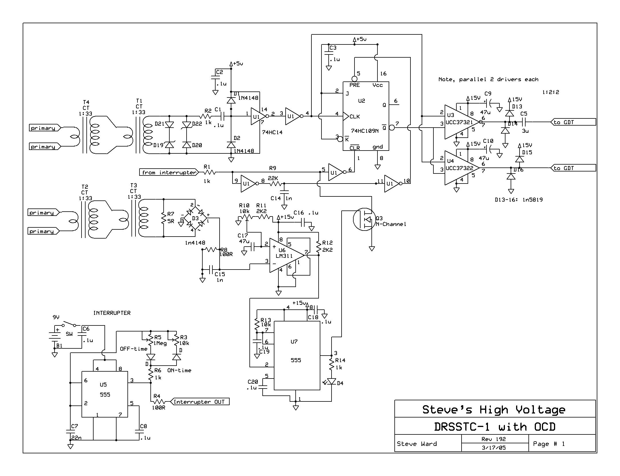 "Link2") , he suggests (I don't remember in which page) to use just one ferrite transformer with a big turn ratio for the inverter signal feedback... will the circuit work with a such high imput impedance at something more than 100KHz?
, he suggests (I don't remember in which page) to use just one ferrite transformer with a big turn ratio for the inverter signal feedback... will the circuit work with a such high imput impedance at something more than 100KHz?
I'm ending the controller board too, I'll post pics as I'll go straight with this... The secondary have been tested under heavy load with the VTTC, its made on a 4" diameter pipe, winding lenght 22", about 2500 turns of 0.25mm wire, for a self resonance of about 160KHz and a toploaded one of about 105... I still have to tune it precisely with the sig gen and the scope.
more to come soon
Andrea
Re: New DRSSTC!
Andrea87, Tue May 29 2007, 08:26PM
I've nearly ended today the driver board, I just have to add some pull-up diodes to the gate drivers outputs and it will be ready to run.
I've calculated the output impedance at 100KHz of the phase lookup transformer, and its about 200Kohm, is it too high for a 1:200 transformer for drsstc use?
The controller board nearly ready:

Phase lookup 1:200 transformer, primary loop is made from 4 layers of 0.01" brass, 1" width. everything is mounted on a teflon base.

at this point the next thing to do is to build the toroid for the coil... since it has worked allways as vttc without it... and then after some tuning finally the first light... looks good!
Since I'm using no doubler for DC source (running off variac + 230V) where do I have to connect the end of the primary LC? do I have to make a capacitive divider for it since I use the half bridge or I can hook it directly to the mains gnd (on the big capacitor)? I have two 6800µF 400V caps that would have a pretty good job here, but putting both of them on would make the power side of the TC really big...
if anyone wants after testing it I'll drop here the eagle pcb artwork.
Andrea
Re: New DRSSTC!
Steve Ward, Wed May 30 2007, 12:47AM
You can tie the primary back to either the + or - of your DC bridge supply (no "voltage divider" necessary).
Also, im not convinced that your MMC will take the abuse of a DRSSTC. They are far harder on tank capacitors than a VTTC. Even a small DRSSTC will run 10's of amps RMS current while a large VTTC might hit a few amps RMS on the tank cap.
Re: New DRSSTC!
Andrea87, Wed May 30 2007, 06:19AM
When used with the vttc there were 3 parallel strings of 12 series cap, and the estimated current was 25-35A RMS (the primary 4mm2 wire was getting easily hot)... now the thing is a little different, 50 parallel blocks of 2 caps, divided in 10x2 boards.
these are the boards before being soldered togheter and wired to the high current connectors:

now there are five of these boards paralleled... I think it will be not too bad work... if it dies I'll ask a friend for some more serious caps :D
Andrea87, Wed May 30 2007, 06:19AM
Steve Ward wrote ...
You can tie the primary back to either the + or - of your DC bridge supply (no "voltage divider" necessary).
Also, im not convinced that your MMC will take the abuse of a DRSSTC. They are far harder on tank capacitors than a VTTC. Even a small DRSSTC will run 10's of amps RMS current while a large VTTC might hit a few amps RMS on the tank cap.
When used with the vttc there were 3 parallel strings of 12 series cap, and the estimated current was 25-35A RMS (the primary 4mm2 wire was getting easily hot)... now the thing is a little different, 50 parallel blocks of 2 caps, divided in 10x2 boards.
these are the boards before being soldered togheter and wired to the high current connectors:

now there are five of these boards paralleled... I think it will be not too bad work... if it dies I'll ask a friend for some more serious caps :D
Re: New DRSSTC!
Steve Ward, Wed May 30 2007, 07:21AM
OK, i completely mis-understood your MMC layout. Nevermind, that should do very well indeed for current. Might want to watch the voltage a bit though!
Steve Ward, Wed May 30 2007, 07:21AM
OK, i completely mis-understood your MMC layout. Nevermind, that should do very well indeed for current. Might want to watch the voltage a bit though!
Re: New DRSSTC!
Andrea87, Wed May 30 2007, 09:47AM
uhm, 3kV should be a good rating for this coil... I suppose I will not go over 400-450w of output power, I'll run it in my garage and I suppose on a decent rf ground (1.5M copper tube dropped into the garden :D ), and also if this mmc goes broken... I've paid 0,01€ per capacitor, so its a mere 1€ of caps there... bought them on a stock, and got all PP film (KP / MKP) caps!
I should have around also something else, some mica caps a lil too "little" (6 pieces 17.6nF 2kV RMS, bought 20 days ago at a local hamfest for the vttc) and some other bigger PP caps... maybe for a future OLTC!
Re: New DRSSTC!
Steve Conner, Wed May 30 2007, 10:24AM
Hi Andrea
The output impedance of the current transformer isn't important. What is important is its self-resonant frequency, this should be far above your operating frequency to prevent serious phase shifts. The more turns you use, the lower the resonance will get. I believe a CT cascade has a higher self-resonant frequency than a single CT with the same ratio, and that's why we use them. Or maybe it's just because few people can be bothered winding 1000 turns on a toroid...
I prefer to use a CT with a modest number of turns (say 33 or 100) and a load that can stand high peak currents. I currently use a back-to-back parallel pair of Schottky rectifiers as the burden, which gives a nice ~1V p-p feedback signal over a wide range of primary currents. I have used it up to about 400A.
You should also be careful that your CT doesn't pick up unwanted signals by inductive coupling from the primary and secondary coils. It has a lot of unshielded loop area.
If you're using a halfbridge with only one electrolytic capacitor, just return the primary circuit to the negative terminal of the capacitor. (FWIW, this is NOT the "mains gnd"! You'll understand the first time you try to clip your scope ground to it!) The divider isn't mandatory, as long as you have a DC block capacitor. In this case, your tank capacitor also functions as the DC block.
Anyway, your work looks good, best of luck!
Re: New DRSSTC!
Marko, Sun Jun 03 2007, 10:06PM
Hi Andrea
That's looking good for now.. regarding your current transformer, I really think of it as too large.. set of two CT's seems to work well to everyone and can have really high stepup ratio (less stress to your clamp zeners.)
The little heatsink is nice... I wonder, are your IGBT's in level with those little 'standoffs'? I just tought it would be cool to mound a PCB on it..
Steve: I tought that shielding of a CT is being somewhat paranoid. Hardly anything can have significant magnetic coupling unless it passes trough the middle of the core.
Electric field from other side can have some effect, but burden and winding impedances are very low for it to have some effect on feedback.
Probably only the scope sense CT may be a good idea to shield.
Re: New DRSSTC!
Steve Conner, Mon Jun 04 2007, 09:58AM
Firkragg, as far as currents that don't pass through the toroid hole are concerned, the CT looks like a single turn air-cored coil with a diameter about equal to the major diameter of the ferrite core it's wound on. So at least an inch or two. I wouldn't care to leave a 1" unshielded loop of signal wiring sticking out anywhere near a Tesla coil primary.
Print this page