
DC Resonant TC
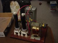
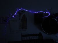
Fessenden, Wed May 16 2007, 02:54AMHello, I am Ben. I have been building coils for several years. Though I would share with the group my most recent coil. It is a DC Resonant design powered by a single 1kW MOT and full wave voltage doubler. Spark gap is a asynchronous (naturally) rotary. I am most proud in that a majority of the components were salvaged from dead FM broadcast transmitter carcasses. An example of this is the large solid state rectifier tube replacements that were just begging to be used.
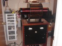
I intended this coil to be more of a furniture / conversation piece than anything, hence the turn-of-the-century quack medicine machine look.
Re: DC Resonant TC
CT2, Wed May 16 2007, 03:38AM
She's beautiful... It really does look turn-of-the-century, great job!
CT2, Wed May 16 2007, 03:38AM
She's beautiful... It really does look turn-of-the-century, great job!
Re: DC Resonant TC
Part Scavenger, Fri May 18 2007, 02:20AM
Hey! That is really cool. Nice work.
Part Scavenger, Fri May 18 2007, 02:20AM
Hey! That is really cool. Nice work.
Re: DC Resonant TC
ShawnLG, Fri May 18 2007, 04:30AM
Nice coil! The voltage doubler looks interesting.
ShawnLG, Fri May 18 2007, 04:30AM
Nice coil! The voltage doubler looks interesting.
Re: DC Resonant TC
Hazmatt_(The Underdog), Fri May 18 2007, 04:42AM
very very nice!
Hazmatt_(The Underdog), Fri May 18 2007, 04:42AM
very very nice!
Re: DC Resonant TC
Fessenden, Fri May 18 2007, 12:21PM
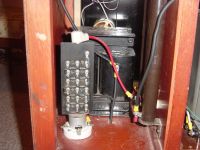
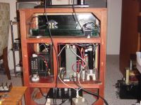
Here is a couple more views of the "business end" of the machine. The close up is of the "de-q-ing" diode, with 8H charging reactor in the background, and to the side the filter network I am using. The diode appears to be a tube replacement assembly that Wilkenson Electronics sold to there customers to retrofit old transmitters.
The second view is an of the entire contents of the machine. You can see my original glass plate cap (0.01uF). I have since started using 2 0.05uF Dearborn plastic caps in series giving 0.025uF. This doubled the spark output, but the caps get somewhat hot. Probably cant handle the current.
This was my first DC coil, and I still have some things to finalize in the construction. One question I have is placement of the filter network in the circuit. I have it between the power supply and the charging reactor. Is this correct, or should I place it between the "de-Q-ing" diode and the tank? Other circuits I have seen have it placed where I have it, but it seems to me that the charging reactor needs some protection from RF. Thoughts?
Second question I have is regarding the "de-Q-ing" diode assembly I am using it is a string of probably 24 1000V 1A diodes in series with small ceramic disc caps in parallel with the diodes. I understand the purpose of the caps, but these also have small neon lamps in parallel with the diode as well. What is the purpose of this, other than looking neat when the current flows?
In case anyone was wondering, I am not a woodworker, I just happened upon a cheap old tube radio cabinet that let it self well to TC construction.


Re: DC Resonant TC
JimG, Fri May 18 2007, 08:58PM
Hey Ben, it's cool to see that you've posted pictures of your coil here. Are you still considering building an MMC for it?
JimG, Fri May 18 2007, 08:58PM
Hey Ben, it's cool to see that you've posted pictures of your coil here. Are you still considering building an MMC for it?
Re: DC Resonant TC
Bert, Sun May 20 2007, 04:17AM
The purpose of the neon lamps (and associated series resistors) is to show, by unlit lamps, if any of the rectifiers have short circuited so that they can be quickly identified and replaced. Suppficient margin is provided by the chain so that a shorted diode or two won't overvolt and cause cascade failures of the rest of the chain.
Re: DC Resonant TC
Fessenden, Sun May 20 2007, 08:08PM
Thanks Bert, that makes sense. That would certainly help troubleshoot a failed transmitter.
Jim, I am still planning on some replacement for the capacitor, probably an MMC. I noticed recently that one of the surplus places has Maxwell 35kV 0.03uF pulse caps for a reasonable amount of money. I may have to get one of those.
Re: DC Resonant TC
sparky, Mon May 21 2007, 12:26AM
WOW! I love the vintage feel I get from this Tesla Coil.... lovely!! Thanks for sharing!
sparky, Mon May 21 2007, 12:26AM
WOW! I love the vintage feel I get from this Tesla Coil.... lovely!! Thanks for sharing!
Print this page