
low budget low voltage uc3842 h-bridge
kerver, Fri Apr 27 2007, 08:09AMHello, Guy's (i never see a female here)
This is my first post

I read the forum for a few years now with fun en joy en think it is time start with something simple.
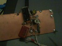
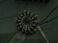
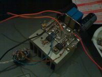
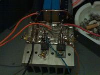
So here it is a low budget uc(un controlled)3842 half bridge.... from the low lands, yeah i life behind a wall next to the sea.
I ad the circuit layout later.
Re: low budget low voltage uc3842 h-bridge
Dalus, Fri Apr 27 2007, 12:20PM
Looks nice, but where are youre zeners and resistors on the gates. And what are you going to do with it drive a small SSTC? Here's an idea, the decoupling caps are on the back of the heat sink.
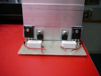
Dalus, Fri Apr 27 2007, 12:20PM
Looks nice, but where are youre zeners and resistors on the gates. And what are you going to do with it drive a small SSTC? Here's an idea, the decoupling caps are on the back of the heat sink.

Re: low budget low voltage uc3842 h-bridge
kerver, Fri Apr 27 2007, 01:58PM
Hi Dulas,
Your bridge looks very clean.
Mine is cut in 2 parts becouse it wash a clean full bridge first.
I don't have any zeners laying here, En i drive it with 16 volt.
But there are very nasty spike's on the begin en end of scoop picture
I use 30 volt 75 ampere fet's from a old ups battrey charger, Boght it in a army dump store 4 euro for 48 fets. (very robuste one's)
It is a hip4082 controller with 4 half bridge's i want to drive a coil with it ,but didn't make same time to check the layout of it.
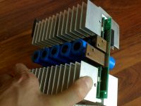
kerver, Fri Apr 27 2007, 01:58PM
Hi Dulas,
Your bridge looks very clean.
Mine is cut in 2 parts becouse it wash a clean full bridge first.
I don't have any zeners laying here, En i drive it with 16 volt.
But there are very nasty spike's on the begin en end of scoop picture

I use 30 volt 75 ampere fet's from a old ups battrey charger, Boght it in a army dump store 4 euro for 48 fets. (very robuste one's)
It is a hip4082 controller with 4 half bridge's i want to drive a coil with it ,but didn't make same time to check the layout of it.

Re: low budget low voltage uc3842 h-bridge
Dalus, Fri Apr 27 2007, 03:04PM
You really need fet's with a higher voltage rating to drive a sstc, I'm using 450 volt fet's for my bridge. Maybe you can post some scope pics so i can find the cause of your voltage spikes.
Dalus, Fri Apr 27 2007, 03:04PM
You really need fet's with a higher voltage rating to drive a sstc, I'm using 450 volt fet's for my bridge. Maybe you can post some scope pics so i can find the cause of your voltage spikes.
Re: low budget low voltage uc3842 h-bridge
kerver, Sun Apr 29 2007, 11:12AM
Here i the schematic.
I now it is not perfect but i draw it fast en it is a low budget vercie.
It works. Nothing more
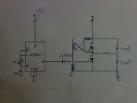
kerver, Sun Apr 29 2007, 11:12AM
Here i the schematic.
I now it is not perfect but i draw it fast en it is a low budget vercie.
It works. Nothing more

Re: low budget low voltage uc3842 h-bridge
Sulaiman, Sun Apr 29 2007, 11:30AM
I also think that the voltage is a little low for good results,
but once it's working you could EASILY convert to dual-resonance mode
where Lp x Cp = Ls x Cs in other words,
make the primary a series resonant circuit at the same frequency as the secondary.
You could either put a 'tuning' capacitor in series with the primary inductor, or better,
change each of the 1uF capacitors for half the required capacitance, and put the two 1uF capacitors across the supply.
Add a fuse (or circuit breaker) because if the UC3844 operates at exactly the resonant frequency,
the current draw will be enormous!
(an interruptor or stochatto circuit is usually used to limit the current rise)
The result will be DRAMATICALLY different.
P.S. a DRSSTC is a good transistor killer

Re: low budget low voltage uc3842 h-bridge
Dr. Shark, Mon Apr 30 2007, 10:10AM
I am surprised the 3842 can source enough current to drive the gates all by itself; Is suppose once you get into Tesla Coil frequencies and voltages you will have to add gate drivers like the TC4422 you can sample here
But then, if you are really going for an SSTC, you better go the whole way with 600V devices, protective Zeners and Varistors etc.
The circuit you have now seems ideally suited to motor control or robotics, so if you want to swap some 30V FETs for 600V FETs let me know
Dr. Shark, Mon Apr 30 2007, 10:10AM
I am surprised the 3842 can source enough current to drive the gates all by itself; Is suppose once you get into Tesla Coil frequencies and voltages you will have to add gate drivers like the TC4422 you can sample here

But then, if you are really going for an SSTC, you better go the whole way with 600V devices, protective Zeners and Varistors etc.
The circuit you have now seems ideally suited to motor control or robotics, so if you want to swap some 30V FETs for 600V FETs let me know

Re: low budget low voltage uc3842 h-bridge
kerver, Wed May 02 2007, 06:03AM
Hello,
So, i have found 2 tc4420, 2 irf2125, gate drive chips 6 irfp460, 2 irf840, 2 irf44 fets en 2 hip4082 en a couple of tl494 in my big used parts store.
Also 4 foil 1uf 630 volt caps, waiting in a box with a lot of big en small (ferriet) trafo's en flyback's.
Now i start to buils a function generator with a xr2206 wich i found to 2, with a bit luck it do 1 mhz.
I now going to look at some picture's here in the forum to build mi full-bridge so i get some idea's for mine.
Is it better to use thermale pads under the fets? when i use 4 seperate cooling blocks?
Futher can somebody help mi with the design with seperate board setup, like drive board > gate drive boards > main (2 half?) bridge boards.
The problem is i don't have a non inverted gate driver.
Thanks
Re: low budget low voltage uc3842 h-bridge
uzzors2k, Wed May 02 2007, 10:17AM
Thermal pads improve the contact to the heatsink, and provide insulation, so I would put some on. Handy incase you ever touch the heatsink!
uzzors2k, Wed May 02 2007, 10:17AM
Thermal pads improve the contact to the heatsink, and provide insulation, so I would put some on. Handy incase you ever touch the heatsink!
Re: low budget low voltage uc3842 h-bridge
Marko, Wed May 02 2007, 08:18PM
Kerver: don't turn mad at me, but there are few critical things that none mentioned among others:
UC3842 is a current mode controller with widely variable duty cycle, and generally very troublesome to set up for a SSTC. NE555 would probably be easier than it!
Your GDT configuration splits voltage in half, and as I see you are using 1:1:1 GDT?
SG3525 would be much better solution in general, but still, for a SSTC, self resonant setup will spare you much of trouble and probably blown mosfets.
Re: low budget low voltage uc3842 h-bridge
kerver, Fri May 04 2007, 08:52AM
yes it is a 1:1:1 gdt
kerver, Fri May 04 2007, 08:52AM
yes it is a 1:1:1 gdt
Re: low budget low voltage uc3842 h-bridge
uzzors2k, Fri May 04 2007, 04:28PM
Which means your mosfets will be driven with +/- 8 volts. If that is under the saturation voltage of your mosfets you'll be driving them in teh linear range, which means alot of heat dissipation. When using push-pull output stages most people use a 1:2:2 ratio, or doubled supply voltage. Also put some small resistors on the gates to prevent LC oscillations. (Small high frequency LC oscillations between gate C and gdt L)
Re: low budget low voltage uc3842 h-bridge
kerver, Tue May 08 2007, 02:50PM
Thanks for the help
kerver, Tue May 08 2007, 02:50PM
Thanks for the help
Re: low budget low voltage uc3842 h-bridge
kerver, Mon Aug 20 2007, 07:56PM
Well, i forget that the gdt was 1 tot 1:1 wind ..
So i rewind the gdt to 1:2:2 en set the voltage on the chip to 18 volts.
I just want a litle fun from this thing, i now it is far from perfect.
But it is perfect to learn, how i have the use my first o-scope!
So when i set the voltage on the fets to 40v ,the output will then swing +/- 20v correct?
Can i then drive a big fet like a irfp460 direct from the output of this ugly bridge? or sould i use a gdt with a cap between it?
Re: low budget low voltage uc3842 h-bridge
Marko, Mon Aug 20 2007, 08:07PM
I don't think you are going to do much with UC38**. You need to manually set duty cycle to 50%, somehow mimic current mode operation and have no deadtime.
Since you are actually using halfbridge, GDT primary sees 1/2 supply voltage so 1:2:2 is fine. Your idea about 40V on mosfet gate is wrong, you will blow it that way. Voltage on gate can make 40V swing but never over 20V in any direction, and since AC is always spoken about as effective value it's said that maximum gate voltage is 20V.
Don't use UC3842, switch to SG3525 instead. You'l be much happier.
Re: low budget low voltage uc3842 h-bridge
thedatastream, Tue Aug 21 2007, 07:32AM
You can DC restore the gate drive signals with a coupling capacitor and a clamp diode which removes the 50% duty cycle problem.
As for mimicing current mode operation, you can inject a portion of the ramp into the Isense pin - there are application notes on how to do this in the 3842 datasheet.
I would be inclined to use a TL494 or a 3525 instead to save you sooooooo much work
Re: low budget low voltage uc3842 h-bridge
kerver, Fri Aug 24 2007, 09:18AM
Oke thanks for the info
Found a 3524, i go with that.
kerver, Fri Aug 24 2007, 09:18AM
Oke thanks for the info
Found a 3524, i go with that.
Print this page