
Micro SSTC design
ShawnLG, Tue Apr 03 2007, 05:34PMSince the Micro RGTC was a sucess, why not build a solid state version as suggested in the other thead. The only problem making a SS coil this small is it's high operating frequency. The secondary has a low inductance and the topload has a miniscule capacitance because of their size. To overcome this, I would need to wind a new seconday with many more turns with finer wire than the micro RGTC had. Below is a schematic I drew up. I need someone to look it over before I start etching boards. This circuit would need to operate in the 1 to 2 mhz range. I may not have any GDT cores that operate at that frequency.
[Edit: Fixed image size
 ]
]Re: Micro SSTC design
thedatastream, Tue Apr 03 2007, 10:37PM
That's an interesting approach to driving a GDT, removes the need for UCC type driver chips.
Winding the GDT for reliable operation at that frequency and in that configuration would not be particularly easy. I would wind 4 turns in parallel, have one for each output and centre-tap the remaining two.
I would also have the GDT primary driven by the outputs of the TL494 in an open collector configuration as these would be better suited for driving FET gates at high frequencies than 2N3904s
I would be very interested to see what results you get with this configuration
James
p.s. There should be no need for D1 and D2 in series with the FET drains
p.p.s Also, a small gate resistor (2 ohm) should be used just to take the edge of the ringing you will get unless the gate drive layout is nice low inductance
Re: Micro SSTC design
..., Wed Apr 04 2007, 12:35AM
hmm, I didn't actually think you would go for it
In any case, for some decent ideas, check the worlds smallest thread, although there is a lot of noise in that thread
Also, I might suggest going for a simpler approach. A tl494, gdt, etc is going to be sorta big for the size of the coil... Your best bet might even be driving the primary directly off a ucc37321/ucc37322 pair, and heck you could probably even get away with just an antenna connected across the inputs of the ucc's and run self resonant
Have fun!
..., Wed Apr 04 2007, 12:35AM
hmm, I didn't actually think you would go for it

In any case, for some decent ideas, check the worlds smallest thread, although there is a lot of noise in that thread

Also, I might suggest going for a simpler approach. A tl494, gdt, etc is going to be sorta big for the size of the coil... Your best bet might even be driving the primary directly off a ucc37321/ucc37322 pair, and heck you could probably even get away with just an antenna connected across the inputs of the ucc's and run self resonant

Have fun!
Re: Micro SSTC design
ShawnLG, Wed Apr 04 2007, 06:29AM
"I would also have the GDT primary driven by the outputs of the TL494 in an open collector configuration as these would be better suited for driving FET gates at high frequencies than 2N3904s"
A TL494 IC would be too big unless they make them in a SMT package. I thought about using a 7406 to directly drive the GDT but it's only rated 48 ma of sink current. I could always replace the 2N3906s with the 2N7000 series but I only have one of them in an smt package. I will need to keep looking.
"Your best bet might even be driving the primary directly off a ucc37321/ucc37322 pair, and heck you could probably even get away with just an antenna connected across the inputs of the ucc's and run self resonant "
I do not have any UCCs.
"In any case, for some decent ideas, check the worlds smallest thread,"
Wow, I didn't know there was a heated competition on mini SSTC.
Re: Micro SSTC design
Ken M., Wed Apr 04 2007, 02:06PM
Technicaly the UCC chips differ from 442X chips just by the enable correct? If thats teh ONLY difference then why not just use a high frequency and gate or just make 1 from schottky diodes, or any diode that can switch relatively fast!
Ken M., Wed Apr 04 2007, 02:06PM
Technicaly the UCC chips differ from 442X chips just by the enable correct? If thats teh ONLY difference then why not just use a high frequency and gate or just make 1 from schottky diodes, or any diode that can switch relatively fast!
Re: Micro SSTC design
..., Wed Apr 04 2007, 02:24PM
Many companies make gate drivers, of the top of my head (in order of increasing power available) microchip, farchild, TI, ixys... There are many 'standard' gate drivers that you can get from any of them, and then there are some monsters made by ixys that can do amazing things. Like swing a 4nf gate in 3ns. We have sorta established that the ucc chips are capable of driving just about anything we will encounter, and they are reasonably priced (you can even sample), the enable is handy for drsstc's, etc.
BTW, put in a side by side test, a tc4422 will run hotter than a ucc37322, but you can get the 4422s in to-220 package which can make up for the difference. But the gate waveforms always look a little nicer with the 327322'a.
As to your original question, any ferrite core will take 1mhz no problem. Once you get >5mhz you really really have to watch your layout and things, but any old core (that isn't powdered iron) will take the frequency.
Re: Micro SSTC design
thedatastream, Wed Apr 04 2007, 08:48PM
Didn't realise that size was a consideration
SMT gate drive ICs are available for reduced size
2N2222 would be a good transistor to use, they are quite quick IIRC
Keep your GDT core size small to reduce the stray inductance
Running at 1-2MHz you can probably use about 250uH GDT inductance without too much problem
I recommend (naturally) ;)
;)
thedatastream, Wed Apr 04 2007, 08:48PM
Didn't realise that size was a consideration
SMT gate drive ICs are available for reduced size
2N2222 would be a good transistor to use, they are quite quick IIRC
Keep your GDT core size small to reduce the stray inductance
Running at 1-2MHz you can probably use about 250uH GDT inductance without too much problem
I recommend (naturally)
 ;)
;)Re: Micro SSTC design
ShawnLG, Thu Apr 05 2007, 06:38PM
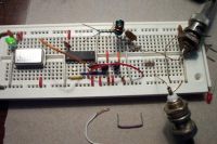
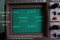
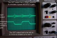
I used datastream's saturation calculation to find a good number of turns for my GDT. I built a prototype using breadboard size components. Below you can see a pic of the setup containing a 1Mhz clock. The IC is a six schmitt trigger inverting hex gates. This give me an inverting and noninverting output for the 2N7000 sitting next to it. I choosed the schmitt trigger because I can easley build an oscillator with it also. Right now the GDT is not working properly. The 250pf capacitor on the GDT output, it is not charging. There is only a small ringing in it.
By the way, the 2N7000 themselfs are working properly. I even tested them on 14.3181Mhz.


Re: Micro SSTC design
..., Thu Apr 05 2007, 06:47PM
Could you post a pic of the scope across the GDT primary?
Also, I don't see a dc blocking cap in series with your gdt, that shouldn't cause your problems but it is a good idea to have it regardles.
..., Thu Apr 05 2007, 06:47PM
Could you post a pic of the scope across the GDT primary?
Also, I don't see a dc blocking cap in series with your gdt, that shouldn't cause your problems but it is a good idea to have it regardles.
Re: Micro SSTC design
ShawnLG, Fri Apr 06 2007, 06:01AM
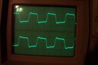
I have found the problem. I had miss crossed one of the primery wires during GDT assembly. Now it works find.
"Also, I don't see a dc blocking cap in series with your gdt, that shouldn't cause your problems but it is a good idea to have it regardles." I don't understand. The primery uses alternating DC pulses.
Below is a picture of the two GDT outputs with their 270pf capacitive load on them.

Re: Micro SSTC design
ragnar, Fri Apr 06 2007, 01:25PM
Without a DC blocking capacitor, if you fire up the power to the gatedrivers without having a signal applied, they're as good as toast.
The series cap allows them to idle, since the capacitor lets only a small initial pulse through. An appropriately sized cap (1uF) will have no effect whilst they're switching AC (high frequency, at least).
Re: Micro SSTC design
Steve Conner, Fri Apr 06 2007, 01:45PM
Seriously though, if Shawn is using the circuit he gave in his first post, where on earth is he going to put the DC block capacitor?
Steve Conner, Fri Apr 06 2007, 01:45PM
Seriously though, if Shawn is using the circuit he gave in his first post, where on earth is he going to put the DC block capacitor?
Re: Micro SSTC design
Marko, Fri Apr 06 2007, 02:08PM
Yes, push-pull is sometimes troublesome because it doesn't support a dc block cap. It may not be important although because gates themselves are capacitive.
Oscillator driven coil in megahertz range is poor choice.
I would strongly suggest you to get some UCC's and use self resonant scheme.
Your current driver doesn't look like it would drive anything but tinyest fet's, and still with huge delays, it looks slow to me even with that 270pF load...
Adding external diodes will also increase parasitic capacitances over the mosfet.
I believe your breadboard is partly messing things up. If you really feel like continuing with this driver, rebuild it on a PCB with shortest possible connections and good decoupling.
Re: Micro SSTC design
ShawnLG, Fri Apr 06 2007, 02:14PM
"Without a DC blocking capacitor, if you fire up the power to the gatedrivers without having a signal applied, they're as good as toast."
I see the problem now. This would cause a problem during an interrupt. I can try putting a capacitor in series with the gates of the MOSFETs with a pull down resistor between the capacitor and the gate.
Re: Micro SSTC design
thedatastream, Fri Apr 06 2007, 09:55PM
Putting series capacitance in the gate will maintain the gate drive amplitude but will introduce a DC shift at the MOSFET gate. Assuming a 50% duty cycle and a 10V drive, you will see ±5V on the gate.
This doesn't get around the problem of an uneven duty cycle causing flux walking in the primary of the core - if one side is on for longer than the other then there is a DC flux component that will slowly build until the top part of the B-H curve hits saturation causing excessive driver currents.
You can't couple the centretap because it has a necessary DC component. You can't couple the collectors of the transistors because the DC component of the push pull is still present in the winding. Coupling the outputs is the same.
All the other clever schemes I can think of all require the use of external FETs or transistors to drive the primary. I would go for a dual MOSFET driver in a SO8 package - maxim do some.
James
Re: Micro SSTC design
Marko, Fri Apr 06 2007, 10:08PM
Flux walking is generally main concern when talking about this.
I don't know any way it could be prevented except minimizing the duty cycle, and so I don't think this as a good topology for mosfet drive.
Proportional base drive transformers use push-pull but only trough a few kiloohm resistor in series with positive supply, and during ''off'' time both transistors are on and keep both primaries shorted together to ground.
There is also a current winding seriesed with halfbridge output wich actually provides the main base drive power, and wich I believe for also keeps the transformer safe from flux walking since there is a DC blocking cap in series with that winding.
Anyway I don't believe this would be much of use for mosfets. They generally wouldn't like their gate voltage to be proportional to drain current, it must be within limits of few volts!
Re: Micro SSTC design
ShawnLG, Tue Apr 24 2007, 07:28AM
It lives!!!
I used a pair of IRF510 to drive the primery. They had a low enuff gate capacitance to not overheat the 2N7000s. But the IRF510s are heating up, even with heat sinks and a fan blowing on them. The SMT 220s would let their smoke out in no time. This could be fixed with an interupter. The coil is also hooked up in DR mode, which give better output. Below are some pics in CW mode. By the way, RF burns hurt!
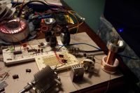
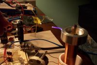
ShawnLG, Tue Apr 24 2007, 07:28AM
It lives!!!

I used a pair of IRF510 to drive the primery. They had a low enuff gate capacitance to not overheat the 2N7000s. But the IRF510s are heating up, even with heat sinks and a fan blowing on them. The SMT 220s would let their smoke out in no time. This could be fixed with an interupter. The coil is also hooked up in DR mode, which give better output. Below are some pics in CW mode. By the way, RF burns hurt!


Re: Micro SSTC design
uzzors2k, Tue Apr 24 2007, 11:41AM
Awesome work ShawnLG! Looks like it's working better than the RSGTC did.
uzzors2k, Tue Apr 24 2007, 11:41AM
Awesome work ShawnLG! Looks like it's working better than the RSGTC did.
Re: Micro SSTC design
Marko, Tue Apr 24 2007, 11:50AM
Especially considering what is he using to drive it!
I see the variable cap.. are you rinning it class E??
Marko, Tue Apr 24 2007, 11:50AM
Especially considering what is he using to drive it!
I see the variable cap.. are you rinning it class E??
Re: Micro SSTC design
ragnar, Tue Apr 24 2007, 01:40PM
Hmm, what do you mean "DR mode" (DR as in dual resonant? How?)
RF burns are nasty. Sure, they happen when you just want to grab a tool to see if you can draw an arc during testing or prototyping, but try not to make them a regular habit. They're worse than blood blisters.
ragnar, Tue Apr 24 2007, 01:40PM
ShawnLG wrote ...
The coil is also hooked up in DR mode, which give better output. Below are some pics in CW mode. By the way, RF burns hurt!


The coil is also hooked up in DR mode, which give better output. Below are some pics in CW mode. By the way, RF burns hurt!


Hmm, what do you mean "DR mode" (DR as in dual resonant? How?)
RF burns are nasty. Sure, they happen when you just want to grab a tool to see if you can draw an arc during testing or prototyping, but try not to make them a regular habit. They're worse than blood blisters.
Re: Micro SSTC design
ShawnLG, Wed Apr 25 2007, 07:00PM
"Hmm, what do you mean "DR mode" (DR as in dual resonant? How?)"
I understand that "DR" means that the primery and the secondary are LC circuits setup in resonant mode. If I got it wrong, someone please explain.
After some more experimenting, I have came up with the best circuit so far. I have notice that my primery was getting super hot so I used litz and it still gets hot. I did notice the litz help the "Q" of the primery. Better streamer length. Below is the circuit so far running in parrelel resonant mode. The voltage swings in the primery tank get so high that a neon bulb can be lit by it.
It looks like the design prossess is almost over. All thats left is the interupter. Now for some questions. Would it be better for the coil to be controlled by an oscallator or have primery feed back? Are there such thing as SMT mica capacitors? I have not seen any. Im afraid to use SMT ciramics on the primery tank, because they may burst into flaims!
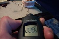
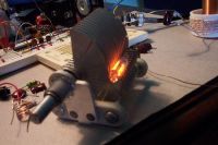


Re: Micro SSTC design
Steve Ward, Thu Apr 26 2007, 12:02AM
Typically parallel resonance isnt used with inverters because you are applying a voltage source that has very high frequency components (square wave). This results in large peak currents every switching transition as your inverter attempts to reverse the charge of the parallel resonant cap.
You really should have a series resonant circuit if you want to go that route, or use a series matching inductor like the LCLR induction heater does.
Re: Micro SSTC design
Tom540, Thu Apr 26 2007, 12:09AM
I was going to mention something about the parallel cap causing high current but Steve explained it much better.
Tom540, Thu Apr 26 2007, 12:09AM
I was going to mention something about the parallel cap causing high current but Steve explained it much better.
Re: Micro SSTC design
ShawnLG, Thu Apr 26 2007, 04:39AM
I have tried to use a series matching inductor but I do not know how to calculate the proper inductance for the circuit.
*****UPDATE*****
I have resolved the h-bridge heating issue and added an interupter. The gates where not being driven to an optimal voltage, they where only seeing +-2.5v I knew about this but since forgot. The GDT was also rewound to efficiently operate at a higher drive voltage. Now the gates see +-10v. I have since blown one IRF510 and one 2SK758 with higher bridge voltage(50v). Now the coil is running with a pair IRF630s. I am surprise that the 2n7000s are running cool when driving all that gate capacitance. Below is a pic showing streamers just oven an inch.
streamer
ShawnLG, Thu Apr 26 2007, 04:39AM
I have tried to use a series matching inductor but I do not know how to calculate the proper inductance for the circuit.
*****UPDATE*****
I have resolved the h-bridge heating issue and added an interupter. The gates where not being driven to an optimal voltage, they where only seeing +-2.5v
 I knew about this but since forgot. The GDT was also rewound to efficiently operate at a higher drive voltage. Now the gates see +-10v. I have since blown one IRF510 and one 2SK758 with higher bridge voltage(50v). Now the coil is running with a pair IRF630s. I am surprise that the 2n7000s are running cool when driving all that gate capacitance. Below is a pic showing streamers just oven an inch.
streamer
Print this page