
Self-oscillating halfbridge flyback driver
Marko, Sat Mar 10 2007, 08:03PMHi everyone
This friday I was too tred to do anythyng but randomly play with some components at hand.
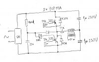
I wanted to see if a flyback could be driven with a small simple blocking oscillator as used in halogen lamp 'electronic transformers'. Off 230V mains, ofcourse.
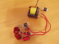
I built one out of some BUT11A transistors and FR309 diodes. It worked beautifully when I hooked it up to an old PC power supply transformer.
I loaded it with a bunch of 24V 5W lamps for some 30..40W (as much as my isolation transformers could give) and transistors were only slightly over room temperature after 10 minutes, without any heatsinks.
Circuit stops oscillating if not loaded enough, but restarts as soon as load comes back.
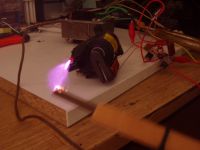
I hooked it to a flyback with 50 turns for primary and pulled off some 5cm arcs, but transistors were overheating in seconds, even when no arcs were drawn and load was minimal.
I wasn't very sure what causes this, the only difference is that flyback is rectified only by a single diode, not being exactly a forward converter, but it has no filter caps, coupling is lower and shouldn't make such problems... I'l try it on AC transformer when I find one.
Output waveform from ATX transformer is much more beautful than I expected.. it's a bit shaky due to diac startup circuit wich kicks in every cycle.. no filter cap on input.
I only blew one transistor, after I tried to run without base resistors. It just shorted out, and I don't have a clue why... currents available in entire circuit are 20mA or so and really shouldn't harm the transistor. So that's a mystery number 2...
Re: Self-oscillating halfbridge flyback driver
Dr. Dark Current, Sat Mar 10 2007, 09:09PM
That's nice. I tried that circuit too , in the past but had some problems with the base drive transformer (it didnt oscillate). when I finally get it to oscillate the driver run relatively cool with low (<50w) powers but was not really good for anything above 100w.
Re: Self-oscillating halfbridge flyback driver
Download, Sat Mar 10 2007, 10:45PM
i have seen that designe before using a halogen lamp electronic transformers seems to work well

Download, Sat Mar 10 2007, 10:45PM
i have seen that designe before using a halogen lamp electronic transformers seems to work well

Re: Self-oscillating halfbridge flyback driver
Marko, Sun Mar 11 2007, 12:58PM
The circuit is easy to get into oscillation. I used a small toroid from CFL bulb and wound two turns for base windings and one feedback turn. It made a nice small low voltage supply with ATX transformer.
I popped two more transistors trying to get it working on a flyback. Transistors just overheat and die in seconds, even on AC transformer, wjile waveform and frequency still look good.
IIRC, solid state NST's use the same circuit, and I'm sure it should work up to several hundred watts without problems. At mains voltage, half an amp per transistor should be enough to melt the flyback anyway with little dissipated heat.
So I have some basic 'mysteries' at this point, I hope some you guys can help:
First, I managed to kill a transistor just because I didn't use btase resistors. Since feedback is from current transformer base current should be proportional to primary current and hardly able to blow the transistor. (BUT11A stands 2 amps of base current).
And second is much more basic; with increase of a load, or increasing the number of primary turns on the current transformer, the working frequency decreases.
This is counter-intuitive, as one would expect the little transformer to saturate faster in both cases and frequency to increase!
I'l see if I can get a commercial halogen lamp transformer and gut it for component investigation and fix mine according to it. Guys on the internet usually don't give out component values...
Marko, Sun Mar 11 2007, 12:58PM
That's nice. I tried that circuit too , in the past but had some problems with the base drive transformer (it didnt oscillate). when I finally get it to oscillate the driver run relatively cool with low (<50w) powers but was not really good for anything above 100w.
The circuit is easy to get into oscillation. I used a small toroid from CFL bulb and wound two turns for base windings and one feedback turn. It made a nice small low voltage supply with ATX transformer.
I popped two more transistors trying to get it working on a flyback. Transistors just overheat and die in seconds, even on AC transformer, wjile waveform and frequency still look good.
IIRC, solid state NST's use the same circuit, and I'm sure it should work up to several hundred watts without problems. At mains voltage, half an amp per transistor should be enough to melt the flyback anyway with little dissipated heat.
So I have some basic 'mysteries' at this point, I hope some you guys can help:
First, I managed to kill a transistor just because I didn't use btase resistors. Since feedback is from current transformer base current should be proportional to primary current and hardly able to blow the transistor. (BUT11A stands 2 amps of base current).
And second is much more basic; with increase of a load, or increasing the number of primary turns on the current transformer, the working frequency decreases.
This is counter-intuitive, as one would expect the little transformer to saturate faster in both cases and frequency to increase!
I'l see if I can get a commercial halogen lamp transformer and gut it for component investigation and fix mine according to it. Guys on the internet usually don't give out component values...
Re: Self-oscillating halfbridge flyback driver
uzzors2k, Mon Mar 12 2007, 08:40PM
Sorry I can't give you any real advice, but I'm no engineer. However this is pretty good reading, and should help you get it working with flyback transformers. I'm looking forward to when you get it working, something small, simple and offline like this is pretty handy, quick and dirty power supplies!

Re: Self-oscillating halfbridge flyback driver
Marko, Mon Mar 12 2007, 08:59PM
Oh, regarding CFL lamps, there are about a ton of schematics.. some people have done really nice work!

As you can see there are different versions of startup circuits, some don't use diacs but just resistors and some kind of DC block to start up the oscillation. AT supplies have same approach as well!
And I mostly done it around these ST appnotes


I although didn't run itno philips appnote you posted, and it indeed looks much more detailed.
Anyway, this seems to require a dissection of a real electronic transformer, as I probably missed out something important. This was more of friday fun than something serious, but I may just get it working better at once.
Marko, Mon Mar 12 2007, 08:59PM
Oh, regarding CFL lamps, there are about a ton of schematics.. some people have done really nice work!

As you can see there are different versions of startup circuits, some don't use diacs but just resistors and some kind of DC block to start up the oscillation. AT supplies have same approach as well!
And I mostly done it around these ST appnotes


I although didn't run itno philips appnote you posted, and it indeed looks much more detailed.
Anyway, this seems to require a dissection of a real electronic transformer, as I probably missed out something important. This was more of friday fun than something serious, but I may just get it working better at once.
Re: Self-oscillating halfbridge flyback driver
uzzors2k, Thu Mar 15 2007, 03:43PM
It may be the lack of deadtime that is catching up to the transistors as power increases. Have you scoped the bases to see if they are overlapping while running the flyback? When I made a smps for my audio amplifier I had a deadtime problem, and the mosfets would die in 30 seconds even with no load. Putting something like the IGBT drive here might help. I would play with this circuit myself, but I only have power mosfets, and no diacs.
Re: Self-oscillating halfbridge flyback driver
Marko, Thu Mar 15 2007, 06:47PM
There actually is a lot of ''deadtime'' on base signals when circcuit is under load wich is probably due to transistor storage times. Circuit as such is protected from shoottrough pretty well because of positive feedback between transistors!
I checked the lamp supply and it uses 2,7 ohm resistors, small one has 1:5:5 and big one has 1:3:3 current transformer.
PC power supplyes from other side seem to use something like 1:8:8, and are fine, I guess it's just a matter of startup 'sensitivity'!
I'm now trying to get a DRSSTC working but I'l play with this circuit more after I get some time and a new bag of transistors! I hoped to get people interested and learn something in process
For mosfets, I just feel they aren't worth of it since it's just so easy and reliable to directly drive them. All schemes with bipolar transistors I seen seem to use this approach regardless If they are controlled or not.
If there is a PWM IC, like in a PC power supply, bipolar transistors with their current transformer are work horses... and controller just reins them with very little power!
Two little transistors slightly bias the core (trough a 1,5k resistor!) to VCC when drive transistor needs to be turned on, and short the transformer out if it needs to turn off.
In AT supplies, there are pull up resistors wich start the blocking oscillation on it's own (wich is required to power the controller) ala those circuits in CFL's. Diac is just sort of option.
Marko, Thu Mar 15 2007, 06:47PM
There actually is a lot of ''deadtime'' on base signals when circcuit is under load wich is probably due to transistor storage times. Circuit as such is protected from shoottrough pretty well because of positive feedback between transistors!
I checked the lamp supply and it uses 2,7 ohm resistors, small one has 1:5:5 and big one has 1:3:3 current transformer.
PC power supplyes from other side seem to use something like 1:8:8, and are fine, I guess it's just a matter of startup 'sensitivity'!
I'm now trying to get a DRSSTC working but I'l play with this circuit more after I get some time and a new bag of transistors! I hoped to get people interested and learn something in process

For mosfets, I just feel they aren't worth of it since it's just so easy and reliable to directly drive them. All schemes with bipolar transistors I seen seem to use this approach regardless If they are controlled or not.
If there is a PWM IC, like in a PC power supply, bipolar transistors with their current transformer are work horses... and controller just reins them with very little power!
Two little transistors slightly bias the core (trough a 1,5k resistor!) to VCC when drive transistor needs to be turned on, and short the transformer out if it needs to turn off.
In AT supplies, there are pull up resistors wich start the blocking oscillation on it's own (wich is required to power the controller) ala those circuits in CFL's. Diac is just sort of option.
Re: Self-oscillating halfbridge flyback driver
robert, Fri Mar 16 2007, 01:49PM
The flyback has a gapped core and therefore has very little primary inductance (compared to the ungapped transformers this is supposed to run with) so primary current will rise very high even with no load.
robert, Fri Mar 16 2007, 01:49PM
The flyback has a gapped core and therefore has very little primary inductance (compared to the ungapped transformers this is supposed to run with) so primary current will rise very high even with no load.
Re: Self-oscillating halfbridge flyback driver
Marko, Fri Mar 16 2007, 02:00PM
Oh... I ungapped the core but failed to mention it Running a gapped transformer with a halfbridge definitely wouldn't be fun for transistors.
Still, sthe leakage inductance is surely higher than of a transformer with overlapped windings, but I don't think it's a big deal. I took care to make it appear as similar as possible to ATX transformer I used first.
Circuits like these run large inductances alone in electronic ballasts and are fine about it.
Marko, Fri Mar 16 2007, 02:00PM
Oh... I ungapped the core but failed to mention it
 Running a gapped transformer with a halfbridge definitely wouldn't be fun for transistors.
Still, sthe leakage inductance is surely higher than of a transformer with overlapped windings, but I don't think it's a big deal. I took care to make it appear as similar as possible to ATX transformer I used first.
Circuits like these run large inductances alone in electronic ballasts and are fine about it.
Re: Self-oscillating halfbridge flyback driver
Steve Conner, Fri Mar 16 2007, 02:05PM
That's neat Firkragg! So an ATX power supply is actually more or less self-oscillating, and the PWM IC just pokes it now and again?
Steve Conner, Fri Mar 16 2007, 02:05PM
That's neat Firkragg! So an ATX power supply is actually more or less self-oscillating, and the PWM IC just pokes it now and again?

Re: Self-oscillating halfbridge flyback driver
Marko, Fri Mar 16 2007, 03:46PM
Sort off. Driver actually uses very little power to drive bipolar transistors just because of large positive feedback from current transformer. If drive was removed in operation halfbridge would continue to work as a blocking oscillator (and probably overvolt and unleash chaos to low voltage components of a supply).
AT supplies also have pullup resistors wich seemingly start the oscillation and power the controller up, as there's no auxiliary supply to do it.
Re: Self-oscillating halfbridge flyback driver
cbfull, Fri Mar 16 2007, 05:57PM
There is a version of that floating around here somewhere that I posted a while back, but I modified it to use resistors to place a bias on the transistors to start the oscillation instead of the diac/capacitor startup circuit.
I was very pleased with the results, and it is the circuit that I will be using from now on. If you like I can try to locate the thread, or you can just search all posts for cbfull, it shouldn't take you very long to find. The nice thing about the circuit is that you don't need any extra gate/base transformers, they are intrinsic to the design.
Re: Self-oscillating halfbridge flyback driver
Marko, Fri Mar 16 2007, 11:41PM
Yes, I remember the thread and app note...
The circuit saves on current transformer but still needs feedback windings to be wound, and I actually find external transformer more neat than it. For the rest of the circuit, it seems doesn't seem to have some special advantage over resonant version.
OK.. Can anyone answer; why operating frequency of (blocking) circuit *decreases* with increase of load? IN all occasions I would expect the little transformer to saturate faster under higher current and thus make the frequency increase. It's still boggling me up!
Marko, Fri Mar 16 2007, 11:41PM
Yes, I remember the thread and app note...

The circuit saves on current transformer but still needs feedback windings to be wound, and I actually find external transformer more neat than it. For the rest of the circuit, it seems doesn't seem to have some special advantage over resonant version.
OK.. Can anyone answer; why operating frequency of (blocking) circuit *decreases* with increase of load? IN all occasions I would expect the little transformer to saturate faster under higher current and thus make the frequency increase. It's still boggling me up!
Re: Self-oscillating halfbridge flyback driver
Dr. Dark Current, Sat Mar 17 2007, 06:59AM
Dr. Dark Current, Sat Mar 17 2007, 06:59AM
Firkragg wrote ...
OK.. Can anyone answer; why operating frequency of (blocking) circuit *decreases* with increase of load? IN all occasions I would expect the little transformer to saturate faster under higher current and thus make the frequency increase. It's still boggling me up!
possibly storage times of driver transistors increase with load?OK.. Can anyone answer; why operating frequency of (blocking) circuit *decreases* with increase of load? IN all occasions I would expect the little transformer to saturate faster under higher current and thus make the frequency increase. It's still boggling me up!
Re: Self-oscillating halfbridge flyback driver
uzzors2k, Sun Mar 18 2007, 08:10PM
Happy Birthday Firkragg! Did you get that DRSSTC working in time for your birthday?
Back on topic, what frequency does the driver drop to while running a flyback? I'm sure you've thought of it already, but if the the frequency is dropping too low, saturating the flyback, which would overheating the transistors. I'll try making a mosfet based version later this week some time, so I can see for myself whats happening.
uzzors2k, Sun Mar 18 2007, 08:10PM
Happy Birthday Firkragg! Did you get that DRSSTC working in time for your birthday?

Back on topic, what frequency does the driver drop to while running a flyback? I'm sure you've thought of it already, but if the the frequency is dropping too low, saturating the flyback, which would overheating the transistors. I'll try making a mosfet based version later this week some time, so I can see for myself whats happening.
Re: Self-oscillating halfbridge flyback driver
Marko, Sun Mar 18 2007, 09:23PM
Thanks..
I ordered some new transistors as well as some ribbon connectors an LM311's for DRSSTC I forgot to buy earlier.
I somehow feel that mosfets will be harder to get working because of their narrow operating region. You may easily overvolt the gates with just slight miscalculation of your current transformer and expected max current. You may need some kind of hard clamping and would probably waste a lot of power there.
Most of new CFL bulbs actually use mosfets in their designs, but I'm not sure how is circuit constructed since it has no current transformer and takes feedback from ballast inductor directly. Ic could be just saturating the whole inductor wich may even not be too big problem since mosfets are very fast, or it may be a resonant circuit ala CFbull's scheme.
Anyway I would much rather use SG3525 and normal GDT since it is way more robust adn mosfets are easy to drive.
Marko, Sun Mar 18 2007, 09:23PM
uzzors wrote ...
Happy Birthday Firkragg! Did you get that DRSSTC working in time for your birthday?
Back on topic, what frequency does the driver drop to while running a flyback? I'm sure you've thought of it already, but if the the frequency is dropping too low, saturating the flyback, which would overheating the transistors. I'll try making a mosfet based version later this week some time, so I can see for myself whats happening.
Happy Birthday Firkragg! Did you get that DRSSTC working in time for your birthday?

Back on topic, what frequency does the driver drop to while running a flyback? I'm sure you've thought of it already, but if the the frequency is dropping too low, saturating the flyback, which would overheating the transistors. I'll try making a mosfet based version later this week some time, so I can see for myself whats happening.
Thanks..
I ordered some new transistors as well as some ribbon connectors an LM311's for DRSSTC I forgot to buy earlier.
I somehow feel that mosfets will be harder to get working because of their narrow operating region. You may easily overvolt the gates with just slight miscalculation of your current transformer and expected max current. You may need some kind of hard clamping and would probably waste a lot of power there.
Most of new CFL bulbs actually use mosfets in their designs, but I'm not sure how is circuit constructed since it has no current transformer and takes feedback from ballast inductor directly. Ic could be just saturating the whole inductor wich may even not be too big problem since mosfets are very fast, or it may be a resonant circuit ala CFbull's scheme.
Anyway I would much rather use SG3525 and normal GDT since it is way more robust adn mosfets are easy to drive.
Re: Self-oscillating halfbridge flyback driver
Marko, Tue Mar 20 2007, 10:49PM
Apparently, they do; more precisely, storage and fall times increase as transistor goes deeper and deeper in saturation.
Large amount of charge needs more time to get removed from the base and thus switching times adn losses increase. Anyway, I tought that any such effect should still be maybe an order of magnitude weaker than response of the current transformer.
I fiddled around a lot last days, and it seems that I basically misunderstood how the circuit was supposed to operate.
At first I tought that it's just better to drive a transistor deep into saturation and make sure it stays there, basically with as much current I can allow it's base to take.
Such gross overdriving of bases must have caused very long storage and fall times. As load is purely inductivetransistors were switching off at maximum current with very long fall times, suffering massive switching losses and blowing themselves out.
The trick, or better said all the point of current transformers are used for is to always keep the ratio of collector and base current same. (proportional base drive).
That way transistor is always kept at or just over saturation with smallest possible charge storage and fall times and circuit operates at maximum efficiency. From what I know, delays can be minimized as much as a factor of ten.
Current transformer, seemingly, needs to be designed with a turns ratio *just lower* than minimal expected current gain gain of the transistor, in order to keep it just around saturation and in sweet spot of operation.
BUT11A's are relatively small, high gain transistors (Hfe 10..20 or so) and would now seem to be best with bigger ratio transformer, 1:8:8 from pc power supply or even bigger looked just fine.
Large transistors like MJE13009 have much lower gain, for this example it wanders from 4..8! This explains why these work well just with 1:3:3 or similar CT.
Current gain varies with load put on transistor, but at low powers higher gain and little bigger switching loss just isn't important. So, transformer is designed around lowest expected Hfe.
****
Just this evening (night) I lashed up a new design using ATX supply BDT (1:8:8??). I also ditched the diac startup circuit and switched to DC block cap + diode with pullup resistor, exactly the circuit as in AT power supply.
I was a bit confused with orientation of the transformer, and after I got it to oscillate the power transformer was giving off terrible sound, looking like it's saturating and transistors were getting hot quickly.
PS. as a sort of update; my frustration continues.
Two times I tried the reconfigured circuit, the transistors failed immediately with their bases shorted out. Even after I completely copied the supposedly working circuit from old AT supply, with same components, I again blew the transistor without having any clue what was going on.
So I'm back on the beggining with a pile of 4 dead BUT's. It's hard to believe that such a small and simple-looking oscillator can be so complex and frustrating to actually get running.
Marko, Tue Mar 20 2007, 10:49PM
possibly storage times of driver transistors increase with load?
Apparently, they do; more precisely, storage and fall times increase as transistor goes deeper and deeper in saturation.
Large amount of charge needs more time to get removed from the base and thus switching times adn losses increase. Anyway, I tought that any such effect should still be maybe an order of magnitude weaker than response of the current transformer.
I fiddled around a lot last days, and it seems that I basically misunderstood how the circuit was supposed to operate.
At first I tought that it's just better to drive a transistor deep into saturation and make sure it stays there, basically with as much current I can allow it's base to take.
Such gross overdriving of bases must have caused very long storage and fall times. As load is purely inductivetransistors were switching off at maximum current with very long fall times, suffering massive switching losses and blowing themselves out.
The trick, or better said all the point of current transformers are used for is to always keep the ratio of collector and base current same. (proportional base drive).
That way transistor is always kept at or just over saturation with smallest possible charge storage and fall times and circuit operates at maximum efficiency. From what I know, delays can be minimized as much as a factor of ten.

Current transformer, seemingly, needs to be designed with a turns ratio *just lower* than minimal expected current gain gain of the transistor, in order to keep it just around saturation and in sweet spot of operation.
BUT11A's are relatively small, high gain transistors (Hfe 10..20 or so) and would now seem to be best with bigger ratio transformer, 1:8:8 from pc power supply or even bigger looked just fine.
Large transistors like MJE13009 have much lower gain, for this example it wanders from 4..8! This explains why these work well just with 1:3:3 or similar CT.
Current gain varies with load put on transistor, but at low powers higher gain and little bigger switching loss just isn't important. So, transformer is designed around lowest expected Hfe.
****
Just this evening (night) I lashed up a new design using ATX supply BDT (1:8:8??). I also ditched the diac startup circuit and switched to DC block cap + diode with pullup resistor, exactly the circuit as in AT power supply.
I was a bit confused with orientation of the transformer, and after I got it to oscillate the power transformer was giving off terrible sound, looking like it's saturating and transistors were getting hot quickly.
PS. as a sort of update; my frustration continues.
Two times I tried the reconfigured circuit, the transistors failed immediately with their bases shorted out. Even after I completely copied the supposedly working circuit from old AT supply, with same components, I again blew the transistor without having any clue what was going on.
So I'm back on the beggining with a pile of 4 dead BUT's. It's hard to believe that such a small and simple-looking oscillator can be so complex and frustrating to actually get running.
Re: Self-oscillating halfbridge flyback driver
uzzors2k, Wed Mar 21 2007, 08:34PM
This is proving to be quite the mystery. I haven't gotten to try anything myself yet as my SGTC is keeping me busy. (Not that I could with contribute much, lol.) Aren't there any engineers here? I saw this a few days ago, a lot of talking in circles but it may help.
uzzors2k, Wed Mar 21 2007, 08:34PM
This is proving to be quite the mystery. I haven't gotten to try anything myself yet as my SGTC is keeping me busy. (Not that I could with contribute much, lol.) Aren't there any engineers here?
 I saw this a few days ago, a lot of talking in circles but it may help.
Re: Self-oscillating halfbridge flyback driver
Marko, Wed Mar 21 2007, 09:14PM
I don't know what was with those PC-power supply BDT's, as I can't see neither number of turns nor orientation, and even while following the original PCB and schematic I could have done something wrong.
I switched back to my little toroid transformer and diac circuit, and it works all fine now up to 30W or so with ATX transformer.
Since I now got and idea how to design a proper proportional-drive transformer, I started increasing secondary turns from 3 to up. At over 6, the transformer started throttling.
5 turns seemed to be a sweet spot for operation, and switching times indeed got much shorter!
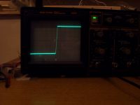
I measured both rise and fall times to be closely 400ns compared to some 1,5..2us as of before, when I used something like 2:3:3 transformer.. what was I doing!
Maybe it could go even faster with a bit of twiddling on a base circuit, but I just didn't want to touch anything.
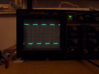
Here are some better pics so you guys can finally see what's all about now. I used a filter cap so I could actually scope something clearly.
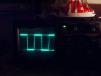
This is primary voltage, at some 40kHz with some 20W load.
Frequency tends to drop pretty much with load. I guess I could get no more than 50W this way without saturation... I use bigger ferrite for CT, as this one is really tiny one from CFL lamp.
The PC power supply CT's from those 200W supplies are often about 1:8:8 or so.. they may have just been too big!
This is closeup on a falling and rise edge, 2us div:
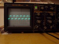
Base voltage, 1V div, at about 50kHz.
Marko, Wed Mar 21 2007, 09:14PM
I don't know what was with those PC-power supply BDT's, as I can't see neither number of turns nor orientation, and even while following the original PCB and schematic I could have done something wrong.
I switched back to my little toroid transformer and diac circuit, and it works all fine now up to 30W or so with ATX transformer.
Since I now got and idea how to design a proper proportional-drive transformer, I started increasing secondary turns from 3 to up. At over 6, the transformer started throttling.
5 turns seemed to be a sweet spot for operation, and switching times indeed got much shorter!
I measured both rise and fall times to be closely 400ns compared to some 1,5..2us as of before, when I used something like 2:3:3 transformer.. what was I doing!
Maybe it could go even faster with a bit of twiddling on a base circuit, but I just didn't want to touch anything.
Here are some better pics so you guys can finally see what's all about now. I used a filter cap so I could actually scope something clearly.
This is primary voltage, at some 40kHz with some 20W load.
Frequency tends to drop pretty much with load. I guess I could get no more than 50W this way without saturation... I use bigger ferrite for CT, as this one is really tiny one from CFL lamp.
The PC power supply CT's from those 200W supplies are often about 1:8:8 or so.. they may have just been too big!

This is closeup on a falling and rise edge, 2us div:

Base voltage, 1V div, at about 50kHz.

Print this page