TRIAC Flyback Driver
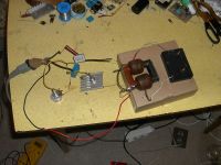
Dr. Dark Current, Sun Feb 25 2007, 02:43PMThis is a very simple and reliable circuit and can be built including the flyback inside a small box. The heart of the circuit is a TRIAC device, basically two antiparallel SCR's. It does not need a heatsink.
The circuit works by discharging a small capacitor through the flyback primary in each mains halfwave, producing a high voltage pulse on the secondary winding. The output spark produces a characteristic crackle at mains frequency, which adds to the "coolness factor".
With more primary turns and bigger capacitor (labeled "C" in the schematic), the produced spark will be much hotter and can be used to drive e.g. a small Jacob's ladder.
This circuit stresses insulation in the flyback's secondary, and breakdown can occur at lower voltages than with high-frequency drivers, but the breakdown is not usually fatal for the flyback because there is not enough energy in the spark to actually damage the insulation.
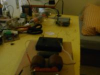
In my setup I used two seriesed secondaries on one core. The output spark can reach about 4cm. After it's tuned I will built it inside a small box (for "high voltage demos"
 )
)

sorry, I couldn't get better picture of the sparks

Re: TRIAC Flyback Driver
uzzors2k, Sun Feb 25 2007, 03:41PM
Nice and simple driver, good job. With no need for an external power supply - w00t!
uzzors2k, Sun Feb 25 2007, 03:41PM
Nice and simple driver, good job. With no need for an external power supply - w00t!
Re: TRIAC Flyback Driver
Dr. Dark Current, Sun Feb 25 2007, 05:39PM
I like this circuit because of its simplicity and because heating of the components is next to none. I was able to get about 6cm spark from my duo-flyback, but I had sparking between one of the secondaries and core, so in final version I will pot the whole thing in wax (from some old candles) for better insulation.
So far I haven't found a way how to regulate power down to zero (or near-zero), if anyone has an idea, it would be great!
Re: TRIAC Flyback Driver
Hazmatt_(The Underdog), Sun Feb 25 2007, 08:21PM
Down to zero? Okay, just rearrange your pot as a divider network and it should go to zero. Try the legs of the pot across your 22nF cap, and the wiper going to your 220K feed resistor.
I should also mention that the 1M in || with the 22nF will probably change your RC time, so you might want to reduce the 22nF to 10nF or less, but give that a shot.
Re: TRIAC Flyback Driver
Dr. Dark Current, Sun Feb 25 2007, 09:00PM
Maybe I should refine my question as, is it possible to control the output *voltage* from zero (or near-zero) to full (this means either from 0 to 90 or from 90 to 180 degrees)? There is a problem that when the triac fires, the kickback from the primary turns it off, so it is possible for it to fire multiple times in each halfwave, and this also results in that it fires quite irregularly.
Dr. Dark Current, Sun Feb 25 2007, 09:00PM
Hazmatt_(The Underdog) wrote ...
Down to zero? Okay, just rearrange your pot as a divider network and it should go to zero. Try the legs of the pot across your 22nF cap, and the wiper going to your 220K feed resistor.
I should also mention that the 1M in || with the 22nF will probably change your RC time, so you might want to reduce the 22nF to 10nF or less, but give that a shot.
hmm... thanks, I tried that, when I turn the pot from one side, the output voltage increases until at one point abruptly turns off.Down to zero? Okay, just rearrange your pot as a divider network and it should go to zero. Try the legs of the pot across your 22nF cap, and the wiper going to your 220K feed resistor.
I should also mention that the 1M in || with the 22nF will probably change your RC time, so you might want to reduce the 22nF to 10nF or less, but give that a shot.
Maybe I should refine my question as, is it possible to control the output *voltage* from zero (or near-zero) to full (this means either from 0 to 90 or from 90 to 180 degrees)? There is a problem that when the triac fires, the kickback from the primary turns it off, so it is possible for it to fire multiple times in each halfwave, and this also results in that it fires quite irregularly.
Re: TRIAC Flyback Driver
Colin 99, Sun Feb 25 2007, 09:19PM
That driver looks alot like the ignition coil drivers using triacs and diacs that I've seem before.
Here's a link for thyristor application notes:

I have some other notes related to this, but I can't remember where I found them.
If you want I can email them to you.
Shaun
Colin 99, Sun Feb 25 2007, 09:19PM
That driver looks alot like the ignition coil drivers using triacs and diacs that I've seem before.
Here's a link for thyristor application notes:

I have some other notes related to this, but I can't remember where I found them.

If you want I can email them to you.
Shaun
Print this page