
ZVS Qs
Myke, Mon Feb 19 2007, 08:27PMHi I’m new here and I built a ZVS flyback transformer driver. I was wondering if there is anything I can do to make it better besides getting better MOSFETs.
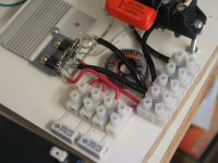
Re: ZVS Qs
cjk2, Mon Feb 19 2007, 08:46PM
IRF740 MOSFET's are 400v, .55ohm devices. If you use something with a higher voltage rating, like 600v, you can use a higher input voltage. Using a device with a lower on resistance will lower the amount of power lost in the MOSFET's, and allow you to push more current before the transistors overheat. Also, use a cap that's bigger than .33uf. Try something like 1uf. How many volts are you currently putting into your driver? What kind of output length are you getting? A pic of your entire setup, including flyback, and primary would be useful. If you have any more questions, just ask, I'd be happy to help.
Re: ZVS Qs
Dr. Dark Current, Mon Feb 19 2007, 09:13PM
Make your leads short and thick- especially those from fets to the resonant cap and from the cap to the primary. Use a thick wire for the primary to avoid overheating. Use a high quality resonant capacitor (PP type or "X2" type found in power supplies works very well). For higher power use better fets, such as the IRFP250.
Hope this helps
w00t, that is some big-ass flyback, I always wanted one of those

Re: ZVS Qs
Myke, Mon Feb 19 2007, 10:00PM
I used IRF740 MOSFETs because I get them for $1 each (I think).
There are 2 caps but one is mostly out of the picture.
I’ve put in 24V a couple of times but mostly I put in 12V.
Oh by the way I get 6 cm arcs at 24V, is this good?
Myke, Mon Feb 19 2007, 10:00PM
I used IRF740 MOSFETs because I get them for $1 each (I think).
There are 2 caps but one is mostly out of the picture.
I’ve put in 24V a couple of times but mostly I put in 12V.
Oh by the way I get 6 cm arcs at 24V, is this good?
Re: ZVS Qs
Marko, Mon Feb 19 2007, 10:07PM
6 cm is pretty good for the voltage. You can generally increase output power at lower voltages by decreasing number of primary turns and increasing the tank capacitor.
ALso, your mosfets are a bit of too high voltage rating and too high Rds ON. Some 100-200 FET's are most used, IRFP250 is one of favorites. IGBT's also work well.
Marko, Mon Feb 19 2007, 10:07PM
Oh by the way I get 6 cm arcs at 24V, is this good?
6 cm is pretty good for the voltage. You can generally increase output power at lower voltages by decreasing number of primary turns and increasing the tank capacitor.
ALso, your mosfets are a bit of too high voltage rating and too high Rds ON. Some 100-200 FET's are most used, IRFP250 is one of favorites. IGBT's also work well.
Re: ZVS Qs
Myke, Tue Feb 20 2007, 02:01AM
Too bad my flyback died by arcing from one pin to the other with no output at all. But what's strange is it only arcs from pin to pin when the HV output is shorted to the ground.
What should I do with the other outputs on the working flybacks?
About what AWG should I use from the fets to the caps?
When I was building it I tried to keep the tips from here in mind.
Myke, Tue Feb 20 2007, 02:01AM
Too bad my flyback died by arcing from one pin to the other with no output at all.
 But what's strange is it only arcs from pin to pin when the HV output is shorted to the ground.
 What should I do with the other outputs on the working flybacks?
About what AWG should I use from the fets to the caps?
When I was building it I tried to keep the tips from here in mind.
Re: ZVS Qs
Myke, Fri Feb 23 2007, 06:31AM
Here is a pic of my flyback that died due to arcing
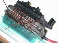
If you number the pins from left to right, 2 arcs to 3 and 3 sometimes arcs to 4. 10 is GND.
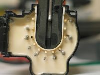
Here is my entire setup.
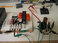
More pics of driver
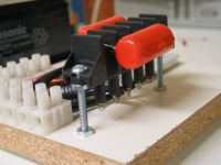
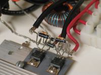
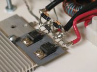
Myke, Fri Feb 23 2007, 06:31AM
Here is a pic of my flyback that died due to arcing

If you number the pins from left to right, 2 arcs to 3 and 3 sometimes arcs to 4. 10 is GND.

Here is my entire setup.

More pics of driver


Re: ZVS Qs
Dr. Dark Current, Fri Feb 23 2007, 01:56PM
If you get arcing on the flyback's base, check for all "groups of pins" (pins that are electrically connected together), and then ground each "group" once. (it doesn't matter which pin in each "group" do you ground)
Dr. Dark Current, Fri Feb 23 2007, 01:56PM
If you get arcing on the flyback's base, check for all "groups of pins" (pins that are electrically connected together), and then ground each "group" once. (it doesn't matter which pin in each "group" do you ground)
Re: ZVS Qs
Myke, Fri Feb 23 2007, 04:37PM
Is it ok that it hapens at 12V because I think it should only do it at 24V or higher? Is the flyback dead because it didn't use to do that before?
Myke, Fri Feb 23 2007, 04:37PM
Is it ok that it hapens at 12V because I think it should only do it at 24V or higher? Is the flyback dead because it didn't use to do that before?
Re: ZVS Qs
Dr. Dark Current, Fri Feb 23 2007, 05:52PM
Dr. Dark Current, Fri Feb 23 2007, 05:52PM
Myke wrote ...
Is it ok that it hapens at 12V because I think it should only do it at 24V or higher? Is the flyback dead because it didn't use to do that before?
If it didn't do that before, and you have no output at all (as you said previously), then yes, it's probably dead (probably from internal insulation breakdown)Is it ok that it hapens at 12V because I think it should only do it at 24V or higher? Is the flyback dead because it didn't use to do that before?
Re: ZVS Qs
Myke, Fri Feb 23 2007, 06:11PM
At 24V the flyback hisses because of corona and I think the corona eventually broke the insulation down. Should I do anything about the other outputs? Does the large capacitor have any thing to do with the HV output?
Myke, Fri Feb 23 2007, 06:11PM
At 24V the flyback hisses because of corona and I think the corona eventually broke the insulation down. Should I do anything about the other outputs? Does the large capacitor have any thing to do with the HV output?
Re: ZVS Qs
uzzors2k, Fri Feb 23 2007, 06:21PM
Large capacitor in the ZVS driver or flyback? If your flyback doesn't put out don't despair, you can salvage the core and make a new flyback. Usually its enough to gorund ouputs that arc to each other.
uzzors2k, Fri Feb 23 2007, 06:21PM
Large capacitor in the ZVS driver or flyback? If your flyback doesn't put out don't despair, you can salvage the core and make a new flyback. Usually its enough to gorund ouputs that arc to each other.
Re: ZVS Qs
Myke, Fri Feb 23 2007, 07:43PM
The flyback has the capacitor. It's the cilinder thing that sticks out on some flybacks. I don't think I have enough skills and matirials to make a flyback.
Myke, Fri Feb 23 2007, 07:43PM
The flyback has the capacitor. It's the cilinder thing that sticks out on some flybacks. I don't think I have enough skills and matirials to make a flyback.

Re: ZVS Qs
uzzors2k, Fri Feb 23 2007, 09:04PM
That capacitor is just a part of the internal recticfier. You'll be surprised by how easy it is to make your own flybacks, lots of the members here have done it. Here is a write up on it, in german, but babelfish does an ok job of translating.
uzzors2k, Fri Feb 23 2007, 09:04PM
That capacitor is just a part of the internal recticfier. You'll be surprised by how easy it is to make your own flybacks, lots of the members here have done it. Here is a write up on it, in german, but babelfish does an ok job of translating.

Re: ZVS Qs
Dr. Dark Current, Fri Feb 23 2007, 09:15PM
The HV filtering capacitor has on many flybacks a separate ground connection, so it is also possible to get sparks between this connection and other pins. If the capacitor connection is grounded, the output will change from a silent hissing arc to a loud buzzing spark.
Re: ZVS Qs
vasil, Fri Feb 23 2007, 09:23PM
Take one good idea from this thread:
http://old.4hv.org/index.php?board=18;action=display;threadid=5379
vasil, Fri Feb 23 2007, 09:23PM
Take one good idea from this thread:
http://old.4hv.org/index.php?board=18;action=display;threadid=5379
Re: ZVS Qs
Myke, Fri Feb 23 2007, 11:32PM
If I were to make multiple layers what matirial should I use? (BTW thanks for all the help) How would I remove the core without breaking it? Are there any other parts that I can remove from a flyback?
Myke, Fri Feb 23 2007, 11:32PM
If I were to make multiple layers what matirial should I use? (BTW thanks for all the help) How would I remove the core without breaking it? Are there any other parts that I can remove from a flyback?
Re: ZVS Qs
uzzors2k, Sat Feb 24 2007, 10:03AM
Put some insulating epoxy over each layer + some HV tape. (can't remember what its called.) The yellow tape from ATX transformers works well, and so does the core. Make sure the insulation stretches well over the layers, as arcing between layers happens easily. Take the metal clamp off the flyback core, and then it should come out easily with some twisting and turning.
Re: ZVS Qs
Myke, Sun Feb 25 2007, 11:56PM
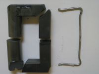
Awhile ago I droped my flyback and the core broke. Should I glue it back together? Should I remove the spacers or not?
[Edit: Fixed double post. Read this: ]
]
Myke, Sun Feb 25 2007, 11:56PM
Awhile ago I droped my flyback and the core broke. Should I glue it back together? Should I remove the spacers or not?

[Edit: Fixed double post. Read this:
 ]
]Re: ZVS Qs
Sulaiman, Mon Feb 26 2007, 01:30AM
Myke, YES, go ahead and glue the broken pieces together.
For a flyback or an inductor or a zvs you need an airgap
(that's where the energy is stored)
Imagine the cores had two 0.75mm spacers, the total airgap would be 1.5mm,
The glued joints would be less than 10% of that so no problem.
The only time an airgap is not required is for a true transformer.
Re: ZVS Qs
Myke, Mon Feb 26 2007, 02:41AM
If I were to use PVC to wind my secondary should I use white PVC because I hear gray and balck PVC have carbon in it?
Here are the vidios of the flyback driver. I'm assuming that the arcs in the second vid are getting shorter because it is near the end of its life.


Myke, Mon Feb 26 2007, 02:41AM
If I were to use PVC to wind my secondary should I use white PVC because I hear gray and balck PVC have carbon in it?
Here are the vidios of the flyback driver. I'm assuming that the arcs in the second vid are getting shorter because it is near the end of its life.


Re: ZVS Qs
uzzors2k, Mon Feb 26 2007, 04:20PM
White PVC would be best, because of the lack of carbon as you say. Steve Ward has some stuff about making your own flybacks. A little OT, but make sure you see his HV pendulum.
  Shortning of the arcs could be due to mosfet heating, increasing their resistance.
uzzors2k, Mon Feb 26 2007, 04:20PM
White PVC would be best, because of the lack of carbon as you say. Steve Ward has some stuff about making your own flybacks.
 A little OT, but make sure you see his HV pendulum.
  Shortning of the arcs could be due to mosfet heating, increasing their resistance.
Re: ZVS Qs
Tonic, Tue Feb 27 2007, 02:52PM
What wire's thickness for secondary wiring would you recommend? I would like this wire to hold a lot of current, let's say, 50mA to 100mA.
Tonic, Tue Feb 27 2007, 02:52PM
What wire's thickness for secondary wiring would you recommend? I would like this wire to hold a lot of current, let's say, 50mA to 100mA.
Re: ZVS Qs
Ambar, Mon Mar 19 2007, 09:16PM
I can change the diode of 400V+ of zvs driver, for the diode 1n4148?
Ambar, Mon Mar 19 2007, 09:16PM
I can change the diode of 400V+ of zvs driver, for the diode 1n4148?
Re: ZVS Qs
Dr. Dark Current, Mon Mar 19 2007, 09:27PM
I have used cca. 0.2mm wire for my flybacks with no problem.
Dr. Dark Current, Mon Mar 19 2007, 09:27PM
Tonic wrote ...
What wire's thickness for secondary wiring would you recommend? I would like this wire to hold a lot of current, let's say, 50mA to 100mA.
it does not have to be very thick, I had one flyback that made very powerful arcs and didn't get hot, and it used hair-thin wire for its secondary. What wire's thickness for secondary wiring would you recommend? I would like this wire to hold a lot of current, let's say, 50mA to 100mA.
I have used cca. 0.2mm wire for my flybacks with no problem.
Re: ZVS Qs
Marko, Mon Mar 19 2007, 09:39PM
Hi
I had an idea of winding homemade transformers using PVC wire from a while ago, but just wasn't about building a proper form. I would definitely go and wind it 'stacked' style ala solid state MOT's rather than layering like flybacks. I believe it would be a very robust solution for a homemade transformer, it would probebly fail only if seriously overheated or maybe from excessive corona (wich shouldn't be too much of a problem if enough clearance is left between forms and not too much wire is put into each form).
I also feel wire would be better 'heatsinked' if wound that way and not potted.
Pick the wire with thickest insulation you have and make a nice former with proper insulation from core, maybe on a lathe of a single block of plastic.
Re: ZVS Qs
Myke, Tue Mar 20 2007, 03:15AM
Or just go with the PVC if some people don't have a lathe? jmartis said that the wire dosn't have to bo too thick and I think it doesn't have to be ethier. I doubt anyone has gone above a couple of amps HV out on a flyback and the single turn voltage shouldn't be that great.
Myke, Tue Mar 20 2007, 03:15AM
Or just go with the PVC if some people don't have a lathe?
 jmartis said that the wire dosn't have to bo too thick and I think it doesn't have to be ethier. I doubt anyone has gone above a couple of amps HV out on a flyback and the single turn voltage shouldn't be that great.
Re: ZVS Qs
cjk2, Tue Mar 20 2007, 04:31AM
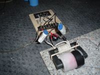
I made a seconday a while back using a piece of 3/4" black pvc as a former. I used packing tape as an insulator between layers, and I did something like 7 layers. I then potted the whole thing in wax. With a ZVS driver and 70 volts in, I got something like 4" sparks out. I used 30AWG wire and had a few hundred turns I think.

Re: ZVS Qs
Part Scavenger, Sat Mar 24 2007, 03:09AM
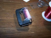
I made one a while back. The inside of trash CD's fits perfectly on the spool, I then made a core of tranparency film, it was very nice.
Also about the sparking between pins, try turning the Screen and (can't remember the other one) Pots down, that usually cuts down on the arcing.

Re: ZVS Qs
Tonic, Sat Mar 24 2007, 01:40PM
Also I've made two weeks ago an homemade secondary winding. I've used ~0.4mm thick wire and half-transparent foil I bought in garden shop. If I remember correctly, I did made 5-6 layers, each has something around 65 coils, so, overall number of them would be like 325-390, giving ratio from 1: 32.5 to 1:39. I don't know if I calculate correctly, but with 40V input at load the output is equal to 1.3-1.5kV. Arc ignities at 2-4mm distance and stretchs to 6-7cm. It may not look great, but the current is horrible! Arc is very bright, enough to make me thinking about welding goggles. Even this arc melts steel.
And the conclusion is that I need to increase ratio in order to obtain higher output voltage and decrease output current. Well, the good thing about selfmade secondaries is that you can made in way that prevents from breaking high voltage insulation. The good idea would be buying big and tall U ferrite core, but it's hard to find and the prices ain't sound funny. (Two pieces of U100 cores costs in my town about 20 euros).
What do you think about painting coils?
Print this page