
Marko's DRSSTC v1.1
Marko, Fri Jan 12 2007, 01:41AMHi everyone over here
I've done some work on a new DRSSTC these holydays. It's practically a whole new coil, secondary and control electronics are only from previous mockup.
I hammered a piece of brass in shape for driver board holder.
THe wide part will also act as an heatsink for bridge rectifier and as single ground point.
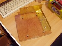
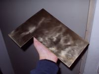
This is another piece of brass. It will be a spine for new H-bridge.
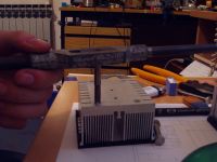
My heatsinks of choice. Cheap Spire CPU heatsinks, with threads engraved in their backs.
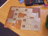
This is how I etched the board for H bridge. I found some old nail varnish my mom threw away. It was quick drying and soft when dry so it was perfect for engraving. I used sticky tape only for larger parts.
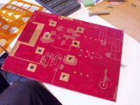
With my primitive etching techniques I couldn't get statisfactionary clearance between copper, so I forced the etching for 2 hours hoping acid will eat through 'edges'. But I ended with lots of small holes in board... luckily just cosmetic.
Board is double sided, and planes are used separately for DC supply to nullify parasitic inductances. I also tinned them, and put large blobs of cheap high-lead solder in places where I needed physical strength and smaller resistance.
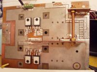
Bridge outputs are used with both sides of the clad in paralell.
Some 30N60's soldered on. Resistors, diodes, TVS and stuff are from other side.
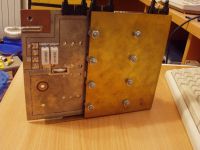
Brass is hammered and everything is bolted together making one pretty robust construction.
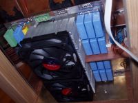
Front side populated. I'l use flat cables to connect gate drive and CT's to the board since they are pretty practical and low inductance.
I hoarded the board with decoupling caps. I put two sets of CT's on board in case I need them.
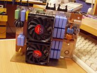
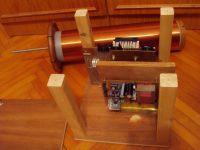
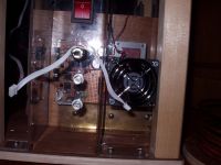
I made this casing in meanwhile. Board and bridge are shown in final arrangement. Secondary is shown in behind. I now need a nice primary form for 6mm copper pipe.
And yeah, bridge needs a proper high current capacitor... I even left exact space for vishay 76*146mm standard cap, but highest voltage I could get here was 100V 21000uF...
I'l also (ofcourse) add a nice acrylic dashboard, and then wire all things up.
I have to wait for toroid to dry it's polyester and most things will be done..
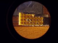
This is how I drilled holes for connectors... I taped a piece of perfboard ona desired place and followed the holes... But, it went very wrong first two tries, until I figured to use large piece of board with lots of tape to hold it in place.
update 13.01.07
toroid
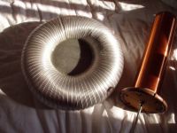
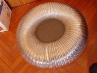
For my top toroid connection, I used a small brass plate wich I can solder the wire to, and it seemed great.
I started thinking about doing the same to the bottom, but then I remembered those red-hot induction heater nuts!
Since this is going to be basically in middle of my primary, I made some cuts in it as shown on pics. I'm going to use weakly magnetic stainless steel screw for it.
I don't know how good idea is it, I can only hope coupling and RMS current will be low enough. Any toughts on it anyone?
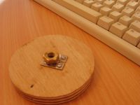
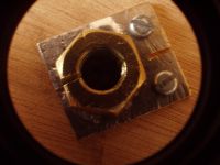
23.1. ...
Some more construction pics. My tripod has died recently beyond fixing. Pics are much uglier now :(
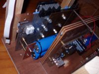
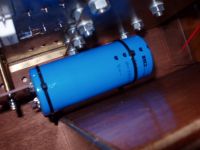
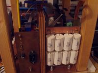
I put two 1000uF 400V caps in paralell as bridge flters.
It's not much, 150 joules, but will be somewhere near lower limit of 20 bang energies.
They also don't look like they are rated forextreme pulse discharges.
I hope to get a real cap at once.
I use my old inty for this coil... it's the only thing that always worked perfectly no matter of anything!
The bent plexi dashboard has a michrophone connector for inty, plus two scope BNC's for tuning. (primary current and drive signal).
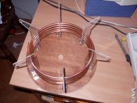
I have enough pipe for the primary... just need a good supports for it.
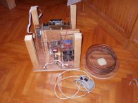
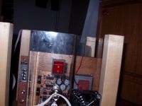
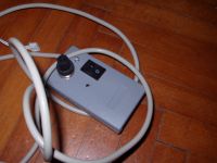
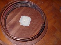
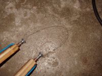
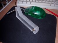
Hot wire plexi bender and cuter. (cutter is just a piece of wire suspended between two wooden sticks, works beautifully!)
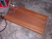
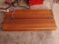
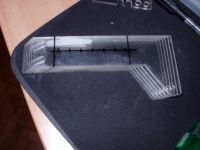
These were pretty ugly after cutting, but then I managed to screw them together (through pre-drilled holes) and polish until perfection. I needed to use 3mm plexi as anyting thicker is tedious to bend.
Then I glued them together to get 2mm displacement. There are 5 of these 'displacements' so I needed to have holes like 10mm spread.
Pipe screwed in. It's nice to finally have a proper primary.
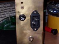
Second pic is mains connector and a fuse.
[Edit: Please don't mess with the formatting of the board]
11.2: so here is the coil, and ghetto MMC. Toroid is somewhere at limit of looking silly.. I hope it will do it's work at least. Just need to screw everything in place and fire it up!
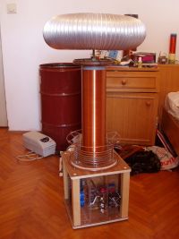
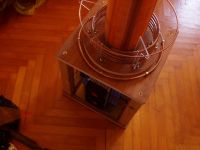
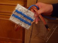
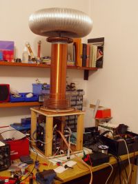
13.3.07: First light, sort of. Ceramic caps are terribly undeperforming considering the power level, so back to the drawing board about them.
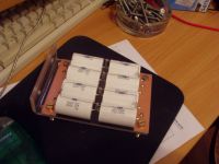
3.6.07. new CDE942C20P15K MMC:
New updates!
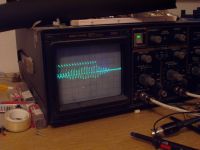
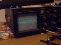
Zero current switching looks perfect.
The primary current on pic is 100A div, 120us. It grows, attempts to heterodyne 3 times and freewheels out after turned off.
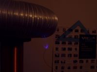
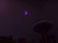
Some small 20cm arcs from toroid for now.
Re: Marko's DRSSTC v1.1
teravolt, Fri Jan 12 2007, 04:34AM
Firkragg I like your work can't wate to see the final product
teravolt, Fri Jan 12 2007, 04:34AM
Firkragg I like your work can't wate to see the final product
Re: Marko's DRSSTC v1.1
ragnar, Fri Jan 12 2007, 04:48AM
Marko, I love the heavy-duty brasswork and some very well designed copper plane. Can't wait to see it in action! =)
ragnar, Fri Jan 12 2007, 04:48AM
Marko, I love the heavy-duty brasswork and some very well designed copper plane. Can't wait to see it in action! =)
Re: Marko's DRSSTC v1.1
Part Scavenger, Fri Jan 12 2007, 03:17PM
That thing is beautiful! Great work!
Part Scavenger, Fri Jan 12 2007, 03:17PM
That thing is beautiful! Great work!
Re: Marko's DRSSTC v1.1
Daniel Uhrenholt, Fri Jan 12 2007, 10:18PM
Nice Work!
I like the CPU heatsinks, time for me to go dumpster diving again
Good luck with it.
Cheers, Daniel
Daniel Uhrenholt, Fri Jan 12 2007, 10:18PM
Nice Work!
I like the CPU heatsinks, time for me to go dumpster diving again

Good luck with it.
Cheers, Daniel
Re: Marko's DRSSTC v1.1
Marko, Sat Jan 13 2007, 12:22AM
Thanks guys
I have the toroid finished, and I'l post pics of it tommorow here.. One more pic now.
Now, I have to find some 3mm acrylic...
And yeah, have to get my signal generator fixed, so I can test the new toroid and finally probe that beastie fulbridge.
Marko, Sat Jan 13 2007, 12:22AM
Thanks guys
I have the toroid finished, and I'l post pics of it tommorow here.. One more pic now.
Now, I have to find some 3mm acrylic...
And yeah, have to get my signal generator fixed, so I can test the new toroid and finally probe that beastie fulbridge.
Re: Marko's DRSSTC v1.1
Steve Ward, Sat Jan 13 2007, 01:58AM
Nice clean work indeed.
One thing i haven't figured out is, where are your electrolytic storage caps for the H-bridge?
Steve Ward, Sat Jan 13 2007, 01:58AM
Nice clean work indeed.
One thing i haven't figured out is, where are your electrolytic storage caps for the H-bridge?
Re: Marko's DRSSTC v1.1
Marko, Sat Jan 13 2007, 10:26AM
I don't have any screw terminal caps of that voltage, although I left space for 76*146mm vishay cap. (holes on left side of board).
I have some 100V 21000uF caps but I would have to stack 4 of these to make them work.
I used 1000uF 400V solder therminal caps before, and I can bolt two there if really needed, although I don't believe anymore they are rated for that high peak currents.
PS: update: toroid...
And, how do you guys generally fix your secondary base? while having a neat ground connection and easily movable secondary?
Marko, Sat Jan 13 2007, 10:26AM
where are your electrolytic storage caps for the H-bridge?
I don't have any screw terminal caps of that voltage, although I left space for 76*146mm vishay cap. (holes on left side of board).
I have some 100V 21000uF caps but I would have to stack 4 of these to make them work.
I used 1000uF 400V solder therminal caps before, and I can bolt two there if really needed, although I don't believe anymore they are rated for that high peak currents.
PS: update: toroid...
And, how do you guys generally fix your secondary base? while having a neat ground connection and easily movable secondary?
Re: Marko's DRSSTC v1.1
Steve Conner, Sat Jan 13 2007, 08:59PM
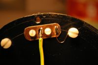
This is how I fixed my secondary base. Conductive metals like copper and brass really don't induction heat much.
Steve Conner, Sat Jan 13 2007, 08:59PM
This is how I fixed my secondary base. Conductive metals like copper and brass really don't induction heat much.

Re: Marko's DRSSTC v1.1
Marko, Sat Jan 13 2007, 09:28PM
Thanks a bunch Steve... I hope this brass plate will be good enough.
Next week I'm going for some 3mm acrylyc, finally a test for my new hot-wire bender.
Marko, Sat Jan 13 2007, 09:28PM
Thanks a bunch Steve... I hope this brass plate will be good enough.
Next week I'm going for some 3mm acrylyc, finally a test for my new hot-wire bender.
Re: Marko's DRSSTC v1.1
Marko, Tue Jan 23 2007, 03:57PM
Hi... updated with lots of new pics. Added plexi bender and cutter.
Marko, Tue Jan 23 2007, 03:57PM
Hi... updated with lots of new pics. Added plexi bender and cutter.
Re: Marko's DRSSTC v1.1
Avalanche, Thu Jan 25 2007, 10:10PM
It's coming on really nicely, good work!
I remember using one of those hot wire plexi benders at school, problem is the heating wire was way too far down - about 4" from the plexi, and I was never able to get good results. I might have to build one like yours and try it again!
Avalanche, Thu Jan 25 2007, 10:10PM
It's coming on really nicely, good work!

I remember using one of those hot wire plexi benders at school, problem is the heating wire was way too far down - about 4" from the plexi, and I was never able to get good results. I might have to build one like yours and try it again!
Re: Marko's DRSSTC v1.1
Marko, Thu Jan 25 2007, 10:28PM
Hi avalanche
Wire is 3-4mm away from plexi on mine, andI actually toughtto bring t closer, but wasn't bothered to find longer screws (these were already becoming unstable).
Wire shouldn't be too hot but should almoust touch acrilyc for best results.
26.1.07: cut primary supports, and added a pic. They aren't looking too good...
Re: Marko's DRSSTC v1.1
Marko, Sat Feb 03 2007, 01:02AM
Hi again.. Updated with some new pics.
One thing that bothers me... C. hooper pointed out steel screws I used on my primary supports.
They are chrome-nickel stainless steel and they don't seem to be noticeably magnetic.
Should I worry about these setting my coil on fire? (plexi wouldn't like to get hot at all.)
I used to have lots of ferrous things around my primary, sometimes even big plates or connection clips and didn't have any trouble...
Re: Marko's DRSSTC v1.1
Dr. Drone, Sat Feb 03 2007, 01:41AM

Dr. Drone, Sat Feb 03 2007, 01:41AM

Re: Marko's DRSSTC v1.1
..., Sat Feb 03 2007, 02:42AM
Hmm, looks like that offset in your primary is creating a pretty decent hot spot in the flux... I wonder how that affects performance?
But in general, I wouldn't worry about the bolts.
..., Sat Feb 03 2007, 02:42AM
Hmm, looks like that offset in your primary is creating a pretty decent hot spot in the flux... I wonder how that affects performance?
But in general, I wouldn't worry about the bolts.
Re: Marko's DRSSTC v1.1
Dr. Drone, Sat Feb 03 2007, 03:56AM

Dr. Drone, Sat Feb 03 2007, 03:56AM

Re: Marko's DRSSTC v1.1
Marko, Sat Feb 03 2007, 07:46PM
Thanks chris.. I'l consider this thing lossy if I ever need to run it at 500W or so, I guess I won't have any problems.
Marko, Sat Feb 03 2007, 07:46PM
Thanks chris.. I'l consider this thing lossy if I ever need to run it at 500W or so, I guess I won't have any problems.
Re: Marko's DRSSTC v1.1
Marko, Sun Feb 11 2007, 12:47AM
'evening.. Pics of almost finished coil finally! Just have to get some more wiring soldered and hooked up, and I hope for a first light tomorrow.
I also remembered I have an large amount of ceramic caps, in one of old MMC's, laying unused. They aren't best choice, but still much better than few polyester caps .
.
Each capacitor is rated 10nF 3kV, and I have 25 strings of 2 in series for 6kV 125nF, surge impedance ~10ohms. I didn't have enough bleeders for them all, so I just used two seris resistors over entire bank.. hope they won't care!
Since there's so many of them, each cap would suffer only 20 amps of peak current if I ran the coil at full 500amps.. with some luck I may get some bigger sparks with them!
Only thing I'm afraid for them is that they'l start to heat up due to losses, and detune the coil all the time due to their gross C/t dependence. Current and frequency are low so I may have some chance.
PS. 26.2. hope to continue this as soon as possible..
Marko, Sun Feb 11 2007, 12:47AM
'evening.. Pics of almost finished coil finally! Just have to get some more wiring soldered and hooked up, and I hope for a first light tomorrow.
I also remembered I have an large amount of ceramic caps, in one of old MMC's, laying unused. They aren't best choice, but still much better than few polyester caps
 .
.Each capacitor is rated 10nF 3kV, and I have 25 strings of 2 in series for 6kV 125nF, surge impedance ~10ohms. I didn't have enough bleeders for them all, so I just used two seris resistors over entire bank.. hope they won't care!

Since there's so many of them, each cap would suffer only 20 amps of peak current if I ran the coil at full 500amps.. with some luck I may get some bigger sparks with them!
Only thing I'm afraid for them is that they'l start to heat up due to losses, and detune the coil all the time due to their gross C/t dependence. Current and frequency are low so I may have some chance.
PS. 26.2. hope to continue this as soon as possible..
Re: Marko's DRSSTC v1.1
Bennem, Sun Feb 11 2007, 08:55AM
Nice looking coil
and well constructed!!
look forward to seeing pics of its first light!
Bennem, Sun Feb 11 2007, 08:55AM
Nice looking coil
and well constructed!!
look forward to seeing pics of its first light!
Re: Marko's DRSSTC v1.1
Marko, Sun Feb 11 2007, 08:24PM
Ahh.. everythyng set ready, and I seem to have a bug on my bridge. I took great care and checked it few times, so no light today
School is going to additionally mess things up, but 'l find some time.
I added a shoot of mess I created...
Marko, Sun Feb 11 2007, 08:24PM
Ahh.. everythyng set ready, and I seem to have a bug on my bridge. I took great care and checked it few times, so no light today

School is going to additionally mess things up, but 'l find some time.
I added a shoot of mess I created...
Re: Marko's DRSSTC v1.1
Marko, Tue Mar 13 2007, 07:25PM
Hi, .. OK, it works.. sort of works.
I finally got myself motivated after a month or so.
Run was at 30V and I got up to some 3 inch sparks, but it tend s to lose feedback and do wierd things again.
Sparks look way more healthy than 15mm sparks my halfbridge coil gave for same input, now I just need to be careful not to do something stupid and blow the IGBT's.
Caps I used are also a bit poor, and they slightly increase temperature even with those short runs!
I surely won't be pumping more power before I get scope connectors and everything fixed in place.
Re: Marko's DRSSTC v1.1
Marko, Fri Mar 16 2007, 03:22PM
at time, I get some 15cm sparks with 18% (60V) input voltage and pretty high ON time, over 250us. At more realistic 100us I seem to get only 10cm sparks.. point to point. There's only some little corona on breakout point and yet coil manages to drive my USB devices completely nuts. I'l have to continue with it in garage.
Part about tuning has become a bit erratic.. coil seems to work better when I tune lower than resonant even at these little powers. If undertuned, ceramic caps start getting hot and change capacitance heavily. And at some point, I got flashovers between primary and secondary, even though primary goes only for 4-5 centimeters over the secondary winding!
PS. just a quicky question about OCD: I see that faster comparators like LM311 are commonly used (wich I don't have any at moment), so can I use something like LM393 (1,3us)? Considering my period of about 10us it looks 'just fine', but should I perfer a faster comparator for some reason?
Re: Marko's DRSSTC v1.1
Steve Ward, Fri Mar 16 2007, 08:30PM
I would think the slow comparator is OK, you can probably compensate by setting the limit a little lower than you would with a faster comparator.
It looks like those ceramic caps might be the source of all your problems... id ditch them if i were you.
Steve Ward, Fri Mar 16 2007, 08:30PM
I would think the slow comparator is OK, you can probably compensate by setting the limit a little lower than you would with a faster comparator.
It looks like those ceramic caps might be the source of all your problems... id ditch them if i were you.
Re: Marko's DRSSTC v1.1
Marko, Sat Mar 17 2007, 12:07AM
I also hate the caps, but they still seem to work better from polyester I used before.. polypropylene are way more stable. I just wanted to see if they would work.
Expecting 400..500A as a final maximum for overdriven TO247 30n60's capacitors would suffer only 10..20 amps of peak curent each, but they simply aren't made for high frequency operation of any kind.
Re: Marko's DRSSTC v1.1
Marko, Wed May 30 2007, 08:19PM
Hi everyone
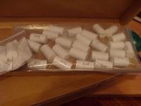
I bought a large amount of 942C20P15K caps and promptly ditched the ceramics.
The project was mothballed for a while (err, 2, or 3 months, or so) due to lack of motivation but I'm pretty sure it will get going now after school is over.
I also have enough caps to build a SGTC and possibly many other things...
These caps are really huge, more massive than I tought.
I don't think I will have easy time blowing those up.

Re: Marko's DRSSTC v1.1
Part Scavenger, Thu May 31 2007, 03:13AM
About time you got to work on that thing!!!!
You do great work! I'm waiting with great expectations...
Part Scavenger, Thu May 31 2007, 03:13AM
About time you got to work on that thing!!!!

You do great work! I'm waiting with great expectations...
Re: Marko's DRSSTC v1.1
teravolt, Thu May 31 2007, 04:27AM
hears what mine loo
teravolt, Thu May 31 2007, 04:27AM
hears what mine loo
Re: Marko's DRSSTC v1.1
teravolt, Thu May 31 2007, 04:38AM
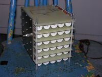
Firkragg nice design,can't wate to see it run. they were big for my project too and this this is how compact I got them. I haven't run them yet so and i dont know if they will flash yet.
teravolt, Thu May 31 2007, 04:38AM
Firkragg nice design,can't wate to see it run. they were big for my project too and this this is how compact I got them. I haven't run them yet so and i dont know if they will flash yet.

Re: Marko's DRSSTC v1.1
Dr. Drone, Sat Jun 02 2007, 04:00AM

Dr. Drone, Sat Jun 02 2007, 04:00AM

Re: Marko's DRSSTC v1.1
Marko, Sun Jun 03 2007, 04:21PM
Teravolt that is one insane MMC... I'm going to use only 8 caps in mine, and I think it's still more than enough...
We've been building air conditioner into my room these days, but I'l be sparking on as soon as I clean the mess over here!
Ps. added a pic of the MMC so you can flame it.
Re: Marko's DRSSTC v1.1
Marko, Thu Jun 07 2007, 11:03PM
Hi..
I did some experimental runs with 30V bus voltage. I set up everything including new MMC, new connections, and OCD. I don't want to make any more noise at past midnight.
I also fixed my coax cables so I don't need to drag probes around anymore.
Current peaks just under 100A with 30V in. it looks like a tad too much, but this tunage made biggest sparks.
With new caps I get 10+cm arcs at this voltage, so they really were worth!
I'l make sure to post a lot of pics tomorrow.
One thing I'm just wondering about, could anybody give me an image of maximum current and spark length I could get with a fullbridge of TO247 30N60's?
.. where should I set my current limiter to make sure not to blow them (the datasheet rating is 240A peak, so I guess not much..)
Re: Marko's DRSSTC v1.1
Steve Ward, Fri Jun 08 2007, 05:20PM
I think Jimmy H made a smaller DRSSTC that used similar IGBTs and ran them at about 500-600A pk, but at a higher frequency. It was a half-bridge and made about 2 foot sparks last i remember.
Anyway, your current will not necessarily grow linearly vs voltage input, since streamer loading is usually non-linear from what ive seen. So it will likely clamp the current to some lower than expected value.
I would expect those IGBTs to handle >350Apk under the right conditions. Of course, they may very well do 2X that.
Re: Marko's DRSSTC v1.1
Marko, Fri Jun 08 2007, 10:27PM
Hey Steve, thanks for this.
U put some more pics at the end of main post.
I did some more runs from isolation transformer (wich liits the power to some 70W) and got some 15..20cm arcs (I keept that really short because of noise, huh!)
I scoped for ZCS and it looks almost perfect as it is now.
THe bad thing has recently happened, and makes me really unhappy with my paranoid low-inductance layout.
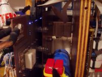
At one point, all sudden, I noticed small arcs jumping between PCB traces on my bridge as I turned the coil on!
Arcs were jumping between DC bus and current transformer traces, seemingly to mains ground.
What seems to be happening is that DC bus, being isolated, capacitively couples to coil's output and builds up high enouhg voltage to start arcing over.
When I disconnected the scope cables the arcs stopped. When circuit board is floating it doesn't seem ot provoke arcs.
They were really small and apparently not energetic enough to do any harm, but they are still really worying me.
They could have blown my GDT or silicone insulators - I haven't even grounded the heatsinks yet!
I think a good solution for this will be two DC-blocking caps of few hundred nf in value from both DC bus rails to system ground.
They may not be needed when running from mains but still I don't want to risk any chances.
EDIT: I have put caps from my DC busses to ground, and grounded the circuit board 'GND'.
At first it looked that arcing stopped, but started showing up again as I drew arcs from the topload! (60V input)
Although impedance between two points is practically nil, I still get kilovolts between them!
I'm really sad and frustrated with this board design.
I tought, I have small clearances between IGBT legs anyway, this should be fine for 300V; etc.. now I guess not.
But even after that I'm in risk of blowing my GDT or something else.
Arcs are very mall and harmless for now, like static, but it makes the thing look like it can do nothing but blow up at somewhat higher input voltage.
Marko, Fri Jun 08 2007, 10:27PM
Hey Steve, thanks for this.
U put some more pics at the end of main post.
I did some more runs from isolation transformer (wich liits the power to some 70W) and got some 15..20cm arcs (I keept that really short because of noise, huh!)
I scoped for ZCS and it looks almost perfect as it is now.
THe bad thing has recently happened, and makes me really unhappy with my paranoid low-inductance layout.
At one point, all sudden, I noticed small arcs jumping between PCB traces on my bridge as I turned the coil on!

Arcs were jumping between DC bus and current transformer traces, seemingly to mains ground.
What seems to be happening is that DC bus, being isolated, capacitively couples to coil's output and builds up high enouhg voltage to start arcing over.
When I disconnected the scope cables the arcs stopped. When circuit board is floating it doesn't seem ot provoke arcs.
They were really small and apparently not energetic enough to do any harm, but they are still really worying me.
They could have blown my GDT or silicone insulators - I haven't even grounded the heatsinks yet!
I think a good solution for this will be two DC-blocking caps of few hundred nf in value from both DC bus rails to system ground.
They may not be needed when running from mains but still I don't want to risk any chances.
EDIT: I have put caps from my DC busses to ground, and grounded the circuit board 'GND'.
At first it looked that arcing stopped, but started showing up again as I drew arcs from the topload! (60V input)
Although impedance between two points is practically nil, I still get kilovolts between them!
I'm really sad and frustrated with this board design.
I tought, I have small clearances between IGBT legs anyway, this should be fine for 300V; etc.. now I guess not.
But even after that I'm in risk of blowing my GDT or something else.
Arcs are very mall and harmless for now, like static, but it makes the thing look like it can do nothing but blow up at somewhat higher input voltage.

Re: Marko's DRSSTC v1.1
Arcstarter, Tue Nov 24 2009, 06:03AM
This is old and outdated, but i am just curious, what ever happened to this?
Arcstarter, Tue Nov 24 2009, 06:03AM
This is old and outdated, but i am just curious, what ever happened to this?
Re: Marko's DRSSTC v1.1
Mates, Thu Nov 26 2009, 04:13PM
Yeah, I even did not see any post from Marco for a while - everything is ok buddy?
Regarding your PCB problem with spark overs:
I have question and also a small advice.
How good is your grounding? It could be the problem...
You can make easily wider isolation paths using small drill with a diamond ball on the tip (every hobby shop sells such drills). After that you could apply some isolation polish.
Re: Marko's DRSSTC v1.1
Steve Conner, Thu Nov 26 2009, 06:21PM
I heard from Marko recently, he just entered 1st year at university (engineering, believe it or not!) and seems to be really busy with work.
Steve Conner, Thu Nov 26 2009, 06:21PM
I heard from Marko recently, he just entered 1st year at university (engineering, believe it or not!) and seems to be really busy with work.
Re: Marko's DRSSTC v1.1
Dalus, Thu Nov 26 2009, 08:27PM
Hehe indeed the first year is quite though, very high studyload. He'll be back when he has some time to spend.
Dalus, Thu Nov 26 2009, 08:27PM
Hehe indeed the first year is quite though, very high studyload. He'll be back when he has some time to spend.
Re: Marko's DRSSTC v1.1
Marko, Fri Nov 27 2009, 04:13PM
Hello guys, thank you. This is such a pleasant surprise to see.
I must admit I stopped posting here a while before I even started the university. I'm not sure why, I think I just got too depressed.
Now my life changed so much that I can't believe it, and at least because I just have to study a lot. I wish I encountered people like this before.
Regarding this coil, I must admit it's mostly in dead-book now. The heatsinks have been taken to make another CW coil which is now at Tesla museum in Smiljan, the control circuit died and was never fixed and there's not much more to be had from the remains. I saved the secondary coil though, and I hope to revive it in big fashion one day, with help of steve. I strongly disbelieve that will happen these holidays, despite I'll take efforts at organizing time I never did in my life, so next summer is most realistic prediction, as I have one near finished project to work on these short holidays.
Marko
Print this page