full-bridge design questions
Kolas, Wed Jan 03 2007, 04:38PMHi all,
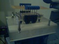
I've been thinking about an H bridge for my large "flyback" transformer. And I have come up with a layout.
I've posted a pic of what I've got so far.
I realise this barely looks like a half bridge; it's missing some things. So please disragard that.
These arent the best screw connectors, but I'm hoping they'll do the job.
At peak I want to conduct 26A rms across this bridge with a voltage of 300v, so my questions are.
Will these connectors add unexpected inductance?
Will isolation (from the heat sink) a considerable issue?
Also, are there any other comments?
My apologies for the poor picutre quality.
Thanks for your input, Kolas


Re: full-bridge design questions
hvguy, Sun Jan 14 2007, 12:05AM
No, inductance is not the big issue with your screw terminals, its contact resistance that would be the problem. If your running 26A RMS that’s probably 5X the manufactures rating for those terminals. It should not be much of a problem and will definitely not affect performance but they might run warm.
Yes, the parts you are using have their middle pin (drain or collector) connected to the metal tab of the case. If they are attached with out pads they will short out your bridge.
hvguy, Sun Jan 14 2007, 12:05AM
Will these connectors add unexpected inductance?
Will isolation (from the heat sink) a considerable issue?
No, inductance is not the big issue with your screw terminals, its contact resistance that would be the problem. If your running 26A RMS that’s probably 5X the manufactures rating for those terminals. It should not be much of a problem and will definitely not affect performance but they might run warm.
Yes, the parts you are using have their middle pin (drain or collector) connected to the metal tab of the case. If they are attached with out pads they will short out your bridge.
Re: full-bridge design questions
Steve Ward, Sun Jan 21 2007, 07:45AM
Is there some reason you mounted the transistors on a smaller heatsink then to a big heatsink, rather than just going straight to the big heatsink? Your current arrangement might hurt performace due to the added thermal resistance (2 junctions instead of 1). Depending on your dissipation, this may or may not matter. 26A at 300V seems like an awful lot of power! I hope your switching frequency isnt too high, or better yet, i hope its zero current switching.
Any more specs on this monster HF transformer?
Re: full-bridge design questions
Kolas, Sun Jan 21 2007, 10:15PM
Hi, thanks for the replies, I kind of figured this thread would fizzle and die.
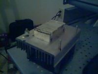
The reason I used the odd heat sink was because of my inability to make a proper PCB. Hopefully with the arrival of some new tools I can change that.
The frequency at which I was to switch was about 50khz. Though without the aid of an inductance meter I really cant progress in that area.
It's a bad day to take a picture as it's rainy and dark, however I will post a picture of the core later.
Steve Ward, I am planning on using the topology you used with a similarly sized core, so switching will be 0 crossing.
Kolas
Re: full-bridge design questions
Steve Ward, Mon Jan 22 2007, 05:52AM
Ah, if you are doing the SLR topology, feel free to ask about any details. Its very reliable when its set up right.
In this case, 26A RMS isnt too insane for the primary current (though my power supplies usually only run around 25-30A pk (~20ARMS). The higher primary currents are due to the resonant nature of the circuit, there is some energy stored in the tank circuit so you end up with a good bit of reactive power as current.
Be sure not to saturate your ferrite! I put a 1 turn sense winding on my transformers so that i could look at the voltage. You get an idea of what the voltage waveform should look like at just a few V into the inverter. As you crank it up, its clear to see if there is saturation, as the voltage starts to "droop" near the end of each half-cycle. The core will also get *very* hot if this happens (so dont run it this way or you will crack your ferrite!).
Re: full-bridge design questions
Kolas, Mon Jan 22 2007, 03:54PM
ok, thanks for the advice!
I've run alot of calculations based on the info your site gave.
My ferrite isn't one whole piece, rather it's made of blocks glued together to give me more cross-sectional area.
This causes worry in me, as it's obviously not as dense as other ferrite cores. I'm most worried about lack of power transfer, it could imped resonation in the primary.
Kolas
Re: full-bridge design questions
Steve Ward, Mon Jan 22 2007, 05:27PM
Your typical ferrite core (E or U cores) will have 2 gaps in the magnetic path. With the SLR topology, it is crucial to minimize any gaps in series with the magnetic path. Hopefully however you glued the thing together, there isnt too much glue inbetween these gaps. The only really negative side effect of the gaps is that it lowers the mutual inductance (lower coupling coefficient). This will have adverse effects when the transformer is left open circuit (like accidentally exciting some resonance when there should be none). You only want resonance to occur when the magnetizing inductance of the transformer is "shorted" (that is, a heavy load on the secondary). When open circuit, the magnetizing L should be large, and swamp out any possible resonance (that is, your inverter drive frequency is far too high for the LC resonance). When you add gaps to the core (or lower its permeability, same thing), the magnetizing inductance is reduced, thus there is less of a difference in resonant frequency when the Lmag is present or when its not.
I should mention that with "paralleling" cores, it is not too critical to remove the air gap between parallel core pieces, since the flux does not have to jump this gap. Also, the ferrite i use on my CCPS has a massive crack in it (an arc-over caused local heating, and cracked it). I simply glued it back together with CA glue, and it works fine. But care must be taken to avoid leaving a large air gap. I do note that a new core (with no cracks) tunes slightly different, and is better behaved under open circuit conditions, but my cracked core is still good enough for me.
Re: full-bridge design questions
Kolas, Wed Jan 24 2007, 04:04AM
well good.
i still havent taken a picture of the core, however i guess i would describe the spacings to be "paralleled" so hopefully they wont cause an issue
Kolas
Kolas, Wed Jan 24 2007, 04:04AM
well good.
i still havent taken a picture of the core, however i guess i would describe the spacings to be "paralleled" so hopefully they wont cause an issue
Kolas
Print this page