Symmetrical Gate Drive Circuit
thedatastream, Fri Dec 22 2006, 12:24PMObtaining an inverted and non-inverted drive signal from a single waveform usually means introducing a delay into one of the outputs by passing it through an inverter. This is especially a problem at higher frequencies (500kHz+) where the delay through an invertor gate, especially with 4000 series CMOS logic, can lead to shoot through on a device.
This can be avoided by using a 4030 or a 4070 CMOS XOR gate in the below configuration. Delay through the CMOS gate is 22ns from input to output, but the outputs are matched to within 6ns on the rising edge and 3ns on the falling edge (measured at 500kHz).
I expect you could get better matching with a fast TTL logic XOR gate.
James
Re: Symmetrical Gate Drive Circuit
Fusion, Fri Dec 22 2006, 01:26PM
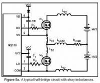
You can use also a mosfet driver.
I like IR2110this one because you would not need a clamping diode and can use two N mosfets

Fusion, Fri Dec 22 2006, 01:26PM
You can use also a mosfet driver.
I like IR2110this one because you would not need a clamping diode and can use two N mosfets

Re: Symmetrical Gate Drive Circuit
ragnar, Fri Dec 22 2006, 03:07PM
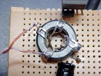
At even higher frequencies, I use a tiny ferrite transformer to invert my signals. You'll see some of the pics in the "HF gate drive experiments" thread.
Below: the four-turn autotransformer is driven between turns #2 and #3. Turn #2 is grounded. Inverting and noninverting outputs can be drawn between #2 and #0, and #2 and #4 at 2x the input voltage.


Print this page