"Stubby" SSTC
thedatastream, Mon Dec 04 2006, 02:39PMFinally...
Originally inspired by Steve Ward's Mini SSTC and started about 2 1/2 years ago, I've finally had enough lunchtimes recently to get it sorted.
A 7" high, 4" diameter secondary running at 250kHz (with topload and 1" CW spark) is driven by a half bridge of STE70NM60 ISOTOP MOSFETs mounted on a section of aluminium U-channel. The bridge is laid out on double sided copper clad PCB with the tracks cut out using a scalpel. Control circuit is Steve Conner's DWSSTC PLL driver and GDT is a bifilar secondary with a coaxial primary, 8 turns on a 22mm Epcos N27 toroid. GDT was good enough to use without series gate resistance. It's all now mounted on a bit of board with antennas and stuff and is looking much better than it used to.
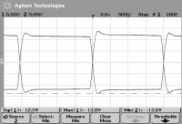
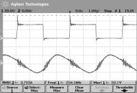
Low input voltage performance is OK when correctly tuned using the phase adjust facility, although there is still ringing on the waveforms. However, the peak on the bridge voltage seems to stay pretty constant with increasing voltage so I'm not too worried.
Gate drive

Bridge voltage and current

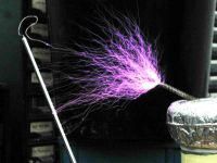
I ran it up to full operating voltage on a variac this lunchtime in the modle shop at work with a colleague acting as Igor. With interrupter set at about 20% duty it belts out streamers with ground strikes at 6 inches with a really loud buzz. Left it running at maximum input for a few minutes, not much heating of transistors, runs great!
Maximum performance of 6" arcs to ground!


Needless to say, I am well chuffed
 , especially after the initial failures with the first layout all those years ago. Next step, less primary turns and see if we can get 7" to ground.
James
Re: "Stubby" SSTC
vasil, Mon Dec 04 2006, 04:52PM
Cool!
vasil, Mon Dec 04 2006, 04:52PM
Cool!
Re: "Stubby" SSTC
Tom540, Tue Dec 05 2006, 06:13AM
Very Nice. I was thinking of trying out that PLL chip recently as well. I've had a few laying around for some time but got discouraged after reading the part about how it might not be that great or something on Conners page. I think I'm going to give it a try this weekend.
Re: "Stubby" SSTC
thedatastream, Tue Dec 05 2006, 01:16PM
Reduced number of primary turns from 9 to 6 and ran up to 270 Vac input. Now giving reliable 7" and very occasional 8" strikes to ground.
Sparks still sound a little bit stuttery at some power levels, possibly there is some interaction between interrupter frequency and mains frequency, or perhaps the PLL misses a beat perhaps.
Once I've added an audio modulator then I shall consider this project finished and keep this as my "demo" coil. An arc-to-ground performance greater than the height of the coil is acceptable in my book.
James
thedatastream, Tue Dec 05 2006, 01:16PM
Reduced number of primary turns from 9 to 6 and ran up to 270 Vac input. Now giving reliable 7" and very occasional 8" strikes to ground.
Sparks still sound a little bit stuttery at some power levels, possibly there is some interaction between interrupter frequency and mains frequency, or perhaps the PLL misses a beat perhaps.
Once I've added an audio modulator then I shall consider this project finished and keep this as my "demo" coil. An arc-to-ground performance greater than the height of the coil is acceptable in my book.

James
Re: "Stubby" SSTC
coaster_chris, Fri Dec 08 2006, 01:02AM
HA! Looking good!
I'm bussy aswell with a SSTC based on Conner's PLL driver.
I've just got some of philips PLL's and Texas Instruments kindly sent me out some UCC 37321/2 MOSFET driver samples.
I have got the sec wound too. 2000 turns of 0.2 mm wire on a 16cm dia PVC former for a nice low Fres.
Now it's time to start frying some solder, and hopefully I'll get it all working. My hopes are kinda low, but hack... just give it a shot!
Just a question before I start mucking around... what is the way to determine the best values voor de VCO cap and resistor? Just by trial and error?
And err, any other tips 'n trick?
Chris
coaster_chris, Fri Dec 08 2006, 01:02AM
HA! Looking good!

I'm bussy aswell with a SSTC based on Conner's PLL driver.
I've just got some of philips PLL's and Texas Instruments kindly sent me out some UCC 37321/2 MOSFET driver samples.

I have got the sec wound too. 2000 turns of 0.2 mm wire on a 16cm dia PVC former for a nice low Fres.
Now it's time to start frying some solder, and hopefully I'll get it all working. My hopes are kinda low, but hack... just give it a shot!

Just a question before I start mucking around... what is the way to determine the best values voor de VCO cap and resistor? Just by trial and error?

And err, any other tips 'n trick?

Chris
Re: "Stubby" SSTC
thedatastream, Fri Dec 08 2006, 08:14AM
Rgds,
James
thedatastream, Fri Dec 08 2006, 08:14AM
coaster_chris wrote ...
Just a question before I start mucking around... what is the way to determine the best values voor de VCO cap and resistor? Just by trial and error?
From Steve's siteJust a question before I start mucking around... what is the way to determine the best values voor de VCO cap and resistor? Just by trial and error?
wrote ...
First of all you have to tune the oscillator part of your PLL so that the resonant frequency of your secondary coil lies within the range. The 470pF cap determines the frequency along with the 33 and 47k resistors. The ratio of these resistors determines how far the VCO can be moved by the PLL. I chose a frequency range of 1.5:1 so it could never lock to a harmonic. So it adjusts from (roughly) 150 to 225 kHz. For a higher frequency secondary, you would need a smaller cap, and/or smaller resistors.
I changed the 470p cap to 270p and the 47k to 56k but left everything else as it was on the schematic. That was for a 250kHz coil.First of all you have to tune the oscillator part of your PLL so that the resonant frequency of your secondary coil lies within the range. The 470pF cap determines the frequency along with the 33 and 47k resistors. The ratio of these resistors determines how far the VCO can be moved by the PLL. I chose a frequency range of 1.5:1 so it could never lock to a harmonic. So it adjusts from (roughly) 150 to 225 kHz. For a higher frequency secondary, you would need a smaller cap, and/or smaller resistors.
Rgds,
James
Re: "Stubby" SSTC
thedatastream, Sun Dec 10 2006, 09:05PM
Website is now updated with stats, info and pictures -
Stubby also won the xmas decoration competition at work with a wireframe tree decorated with neon lamps and a star emiting streamers on the top! OK, I won by default - no other entries this year - but working for an engineering firm there would have been more than a few votes from the engineers I reckon. Still, won a nice bottle of red for the first prize
I'm going to focus on a smaller coil next, christened "Titch". Expect a project thread at some point.
James
thedatastream, Sun Dec 10 2006, 09:05PM
Website is now updated with stats, info and pictures -

Stubby also won the xmas decoration competition at work with a wireframe tree decorated with neon lamps and a star emiting streamers on the top! OK, I won by default - no other entries this year - but working for an engineering firm there would have been more than a few votes from the engineers I reckon. Still, won a nice bottle of red for the first prize

I'm going to focus on a smaller coil next, christened "Titch". Expect a project thread at some point.
James
Re: "Stubby" SSTC
Marko, Sun Dec 10 2006, 09:39PM
I don't get why are you using monster 70 ampere mosfets, but coil looks nice indeed. Any idea of power going into it?
Marko, Sun Dec 10 2006, 09:39PM
I don't get why are you using monster 70 ampere mosfets,
 but coil looks nice indeed. Any idea of power going into it?
 Re: "Stubby" SSTC
thedatastream, Mon Dec 11 2006, 01:35PM
Anyway, large SSTC got dumped - too large to run on desk at work and too much fuss to set up. I decided to re-use the FETs instead of selling them on eBay.
The moving iron meters on top of my variac read approx 270V and 2A when hitting 7" strikes running at about 20% interrupted. I don't know how accurate they are for pulsed current running through them but this equates to about 550W.
James
thedatastream, Mon Dec 11 2006, 01:35PM
Firkragg wrote ...
I don't get why are you using monster 70 ampere mosfets, but coil looks nice indeed. Any idea of power going into it?
I started off building a bigger SSTC before starting Stubby so I wanted some decent transistors. I had a word with our ST rep and they sponsored me with 25 of those FETs. I must get around to adding a logo or something onto my webpage by way of thanks.I don't get why are you using monster 70 ampere mosfets, but coil looks nice indeed. Any idea of power going into it?
Anyway, large SSTC got dumped - too large to run on desk at work and too much fuss to set up. I decided to re-use the FETs instead of selling them on eBay.
The moving iron meters on top of my variac read approx 270V and 2A when hitting 7" strikes running at about 20% interrupted. I don't know how accurate they are for pulsed current running through them but this equates to about 550W.
James
Print this page