
Function and form....
Ash Small, Wed Oct 24 2018, 11:18PMJust soldered this up.... More to come in a 'Poject' thread soon, but my layouts appear to be improving almost to the form of art.... couple of 'errors', maybe, but getting there.....
I bet no-one can guess what it's designed to drive?..... not tested it yet, it might require a bit of tuning.....

Re: Function and form....
Ash Small, Sun Oct 28 2018, 11:55PM
I managed to fry the first version because I'd believed the textbooks and was trying to measure voltage instead of current..... Ohm's law isn't easy to apply to the output of this circuit...... The Mk 2 version is complete overkill, and I exceeded the output requirements as soon as I started tweaking.... Adding extra parallel resistors to the source..... I need to do a bit more tweaking to learn the true nature of this creature, but it has so far exceeded all expectations, and I feel I've barely begun yet..... More to follow.....

Re: Function and form....
Ash Small, Sat Nov 03 2018, 02:34AM
Latest incarnation, the Mk 3.... It's getting there.... Explanation to follow shortly.....

EDIT: I needed to add a parallel resistor to the source.....
Ash Small, Sat Nov 03 2018, 02:34AM
Latest incarnation, the Mk 3.... It's getting there.... Explanation to follow shortly.....

EDIT: I needed to add a parallel resistor to the source.....
Re: Function and form....
Ash Small, Wed Nov 07 2018, 07:15PM
So this is the current circuit.....

There are still a few mods I want to try..... I think I can improve efficiency, but it performs splendidly 'as is'.....
Ash Small, Wed Nov 07 2018, 07:15PM
So this is the current circuit.....

There are still a few mods I want to try..... I think I can improve efficiency, but it performs splendidly 'as is'.....
Re: Function and form....
Shrad, Mon Nov 12 2018, 10:55AM
I bet those would make some nice voltage followers which sound as good as one could expect... what is the range of gate capacitance?
Shrad, Mon Nov 12 2018, 10:55AM
I bet those would make some nice voltage followers which sound as good as one could expect... what is the range of gate capacitance?
Re: Function and form....
Sulaiman, Mon Nov 12 2018, 11:28AM
Is it a bi-phasic jfet terminator ?
I do not know the application but it is clearly not for a true sinewave output,
and the component values seem 'odd' for 1 kHz operation,
what is it for ?
It looks to me that you have wired j105's in parallel,
If your fets get inexplicably hot it may be due to parasitic oscillations,
probably at such high frequency that all your 'scope will 'show' is a thick fuzzy trace instead of a nice thin line,
if so then ferrite beads on jfet leads will help.
Generally, using UHF transistors in low frequency circuits can cause parasitic oscillations
- if the designer is not familiar with r.f. design.
The common symptoms are
. unexpectedly high current draw or component heating
. at certain levels in waveforms the 'scope trace looks 'fuzzy'
. 'scoping at different points gives inconsistent waveforms due to the 'scope lead aiding or loading a self-oscillating circuit.
No obvious sign of parasitic oscillation in the 'photo above but something worth keeping an eye open for.
Re: Function and form....
Shrad, Tue Nov 13 2018, 07:23AM
I failed at looking some pictures and did not see jfet part number, so assumed it was one of those power JFET
maybe you want to try cascode operation? there is a nice example at
Shrad, Tue Nov 13 2018, 07:23AM
I failed at looking some pictures and did not see jfet part number, so assumed it was one of those power JFET
maybe you want to try cascode operation? there is a nice example at
Re: Function and form....
Plasma, Tue Nov 13 2018, 09:23AM
If you want ac voltage emitter ,a capacitor in series on the top right leg,to remove the DC bias
Plasma, Tue Nov 13 2018, 09:23AM
If you want ac voltage emitter ,a capacitor in series on the top right leg,to remove the DC bias
Re: Function and form....
Ash Small, Wed Nov 14 2018, 12:02AM
35-160pF
Interesting article you've linked to. While these are only rated for 25Vdg, I'm running them from a 38V supply, as at least 15V is across the drain resistor, so the device 'sees' less than 25V.
(EDIT: I've just realised what you mean by voltage follower.... Yes, it seems to be an 'ideal' voltage follower )
It'gives a perfect sinewave output, Suliaman.
They seem to work in parallel exactly the same as individually. No 'fuzzy' trace, just perfect sine wave.
It's actually for driving a spring reverb tank with input impedence of 8 Ohms. As you're aware this is the impedence at 1kHz, at ten kHz impedence is 80 Ohms. It requires at least 28mA, with the series resistor of 246 Ohm, at 10kHz, total impedence is 326 Ohms, and it is driving 36mA @ 1kHz and 30mA @ 10kHz, with a perfect sine wave.
These are nothing like the JFET's from 50 years ago, things have moved on a bit since then....
(EDIT: regarding your point re. parasitic oscillations when using fast switches..... Would that be when using solid state voltage controllers?..... I wanted to avoid them because I could foresee that kind of problem, I'm only using copper and iron for voltage regulation with this circuit. 'Old Skool' technology.....
the capacitor on the bottom leg blocks any DC. The resistor on the top leg is to reduce the difference in current at 1kHz and 10kHz by giving a total impedence at 1kHz of 254 Ohms and a total at 10kFz of 326 Ohms.
connecting the output in this way isolates the output. It also provides a very low impedence output.
This is the latest incarnation, I'm driving it with a more conventional JFET topology stage which gives a gain of 25 because this circuit needs to be driven with a signal of 8V P-P. I still need to add some filtering to the gain stage, though.

Ash Small, Wed Nov 14 2018, 12:02AM
Shrad wrote ...
I bet those would make some nice voltage followers which sound as good as one could expect... what is the range of gate capacitance?
I bet those would make some nice voltage followers which sound as good as one could expect... what is the range of gate capacitance?
35-160pF
Interesting article you've linked to. While these are only rated for 25Vdg, I'm running them from a 38V supply, as at least 15V is across the drain resistor, so the device 'sees' less than 25V.
(EDIT: I've just realised what you mean by voltage follower.... Yes, it seems to be an 'ideal' voltage follower
)Sulaiman wrote ...
Is it a bi-phasic jfet terminator ?
I do not know the application but it is clearly not for a true sinewave output,
and the component values seem 'odd' for 1 kHz operation,
what is it for ?
It looks to me that you have wired j105's in parallel,
If your fets get inexplicably hot it may be due to parasitic oscillations,
probably at such high frequency that all your 'scope will 'show' is a thick fuzzy trace instead of a nice thin line,
if so then ferrite beads on jfet leads will help.
Generally, using UHF transistors in low frequency circuits can cause parasitic oscillations
- if the designer is not familiar with r.f. design.
The common symptoms are
. unexpectedly high current draw or component heating
. at certain levels in waveforms the 'scope trace looks 'fuzzy'
. 'scoping at different points gives inconsistent waveforms due to the 'scope lead aiding or loading a self-oscillating circuit.
No obvious sign of parasitic oscillation in the 'photo above but something worth keeping an eye open for.
It'gives a perfect sinewave output, Suliaman.
They seem to work in parallel exactly the same as individually. No 'fuzzy' trace, just perfect sine wave.
It's actually for driving a spring reverb tank with input impedence of 8 Ohms. As you're aware this is the impedence at 1kHz, at ten kHz impedence is 80 Ohms. It requires at least 28mA, with the series resistor of 246 Ohm, at 10kHz, total impedence is 326 Ohms, and it is driving 36mA @ 1kHz and 30mA @ 10kHz, with a perfect sine wave.
These are nothing like the JFET's from 50 years ago, things have moved on a bit since then....
(EDIT: regarding your point re. parasitic oscillations when using fast switches..... Would that be when using solid state voltage controllers?..... I wanted to avoid them because I could foresee that kind of problem, I'm only using copper and iron for voltage regulation with this circuit. 'Old Skool' technology.....
Plasma wrote ...
If you want ac voltage emitter ,a capacitor in series on the top right leg,to remove the DC bias
If you want ac voltage emitter ,a capacitor in series on the top right leg,to remove the DC bias
the capacitor on the bottom leg blocks any DC. The resistor on the top leg is to reduce the difference in current at 1kHz and 10kHz by giving a total impedence at 1kHz of 254 Ohms and a total at 10kFz of 326 Ohms.
connecting the output in this way isolates the output. It also provides a very low impedence output.
This is the latest incarnation, I'm driving it with a more conventional JFET topology stage which gives a gain of 25 because this circuit needs to be driven with a signal of 8V P-P. I still need to add some filtering to the gain stage, though.

Re: Function and form....
Plasma, Wed Nov 14 2018, 12:59AM
I see, would the voltage and current be in phase, voltage leg would get less affected by a capacitor, thand the lower leg current leg,
Does this sound right?
Plasma, Wed Nov 14 2018, 12:59AM
I see, would the voltage and current be in phase, voltage leg would get less affected by a capacitor, thand the lower leg current leg,
Does this sound right?
Re: Function and form....
Ash Small, Wed Nov 14 2018, 04:33AM
I don't know... I wasn't sure about this, but I needed an isolated output, and I'd seen this implemented once on a tube amp designed by 'trial and error' rather than theory.
It's customary to fit a capacitor between source and ground (or B- ), in parallel with the source resistor to maximise gain, so I figured maybe connecting the cap to source 'may' have a similar effect.
I can't see it really makes much difference, since the cap is still in series with the load between both points.
I may yet fit a capacitor in parallel with the load, to act as a low pass filter in conjunction with the resistor. I'm still calculating various filter combinations, but it will come down to trial and error (ear). I need high pass, low pass and maybe a conditioning low pass filter. This 'could' go on the output, or on the input of one of the transistors. I'm not even sure I'll need it yet, but it's something I want to experiment with.
EDIT: I've just re-read Plasma's post..... The voltage and current do some strange things, well, mostly the voltage, and Plasma mentioning phase has just caused me to realise why....
there is a point when adjusting the source resistor when there is no voltage across the load, but still maximum current.
either side of this point the voltage rises
I guess at that point they are in phase.
I guess thats where I should adjust it to.
The voltages across the drain resistor and source resistor, I believe, go up and down alternately..... I guess this adds some feedback. It's a remarkable little circuit
EDIT: Actually, the scope is connected to the upper side of the load and ground, which, I think suggests the voltage across the transistor remains constant at all times, or the voltage across the source resistor varies, .....
Ash Small, Wed Nov 14 2018, 04:33AM
Plasma wrote ...
I see, would the voltage and current be in phase, voltage leg would get less affected by a capacitor, thand the lower leg current leg,
Does this sound right?
I see, would the voltage and current be in phase, voltage leg would get less affected by a capacitor, thand the lower leg current leg,
Does this sound right?
I don't know... I wasn't sure about this, but I needed an isolated output, and I'd seen this implemented once on a tube amp designed by 'trial and error' rather than theory.
It's customary to fit a capacitor between source and ground (or B- ), in parallel with the source resistor to maximise gain, so I figured maybe connecting the cap to source 'may' have a similar effect.
I can't see it really makes much difference, since the cap is still in series with the load between both points.
I may yet fit a capacitor in parallel with the load, to act as a low pass filter in conjunction with the resistor. I'm still calculating various filter combinations, but it will come down to trial and error (ear). I need high pass, low pass and maybe a conditioning low pass filter. This 'could' go on the output, or on the input of one of the transistors. I'm not even sure I'll need it yet, but it's something I want to experiment with.
EDIT: I've just re-read Plasma's post..... The voltage and current do some strange things, well, mostly the voltage, and Plasma mentioning phase has just caused me to realise why....
there is a point when adjusting the source resistor when there is no voltage across the load, but still maximum current.
either side of this point the voltage rises
I guess at that point they are in phase.
I guess thats where I should adjust it to.
The voltages across the drain resistor and source resistor, I believe, go up and down alternately..... I guess this adds some feedback. It's a remarkable little circuit
EDIT: Actually, the scope is connected to the upper side of the load and ground, which, I think suggests the voltage across the transistor remains constant at all times, or the voltage across the source resistor varies, .....
Re: Function and form....
Shrad, Wed Nov 14 2018, 06:55AM
as you need high pass wouldn't a cascode arrangement be a better fit at higher frequencies?
for filtering, you can also use NFB the japanese way
Shrad, Wed Nov 14 2018, 06:55AM
as you need high pass wouldn't a cascode arrangement be a better fit at higher frequencies?
for filtering, you can also use NFB the japanese way
Re: Function and form....
Ash Small, Wed Nov 14 2018, 07:25AM
I've just had a quick look at cascode, and I don't think it would work with this topology. From what I can see, the cascode circuit requires one side of the load to be grounded, thus not isolated output.
I'm a minimalist, I try to keep my circuits to the absolute minimum component count. I know virtually nothing about feedback, I'm only just beginning to learn about filters. I've worked out that if you have two capacitors connected to the same node, the one with a smaller value will tend to develop a higher voltage across it, all other things being equal, which they are not when you add a couple of resistors...
Ash Small, Wed Nov 14 2018, 07:25AM
Shrad wrote ...
as you need high pass wouldn't a cascode arrangement be a better fit at higher frequencies?
for filtering, you can also use NFB the japanese way
as you need high pass wouldn't a cascode arrangement be a better fit at higher frequencies?
for filtering, you can also use NFB the japanese way
I've just had a quick look at cascode, and I don't think it would work with this topology. From what I can see, the cascode circuit requires one side of the load to be grounded, thus not isolated output.
I'm a minimalist, I try to keep my circuits to the absolute minimum component count. I know virtually nothing about feedback, I'm only just beginning to learn about filters. I've worked out that if you have two capacitors connected to the same node, the one with a smaller value will tend to develop a higher voltage across it, all other things being equal, which they are not when you add a couple of resistors...
Re: Function and form....
Shrad, Wed Nov 14 2018, 08:48AM
that's not really an isolated circuit, is it?
maybe an AC coupled differential output would better fit then? just a suggestion of course
EDIT:
like the input stage of this diagram :

EDIT again:
just found this and thought it was especially on-topic : https://www.edn.com/electronics-blogs/anablog/4307462/Your-friend-the-JFET-
Shrad, Wed Nov 14 2018, 08:48AM
that's not really an isolated circuit, is it?
maybe an AC coupled differential output would better fit then? just a suggestion of course
EDIT:
like the input stage of this diagram :
EDIT again:
just found this and thought it was especially on-topic : https://www.edn.com/electronics-blogs/anablog/4307462/Your-friend-the-JFET-
Re: Function and form....
Ash Small, Wed Nov 14 2018, 02:39PM
Why is it not isolated output?..... It's de-coupled from the source resistor via the output cap?..... Would a de-coupling cap on the drain make it isolated, or am I missing something?
I'll try googling it.....
Ash Small, Wed Nov 14 2018, 02:39PM
Shrad wrote ...
that's not really an isolated circuit, is it?
maybe an AC coupled differential output would better fit then? just a suggestion of course
EDIT:
like the input stage of this diagram :
EDIT again:
just found this and thought it was especially on-topic : https://www.edn.com/electronics-blogs/anablog/4307462/Your-friend-the-JFET-
Why is it not isolated output?..... It's de-coupled from the source resistor via the output cap?..... Would a de-coupling cap on the drain make it isolated, or am I missing something?
I'll try googling it.....
Re: Function and form....
Shrad, Wed Nov 14 2018, 03:12PM
when your jfet is conducting your upper output leg is coupled with ground via the transistor (which is the case most of the time) so your output is always coupled to your input in some manner
in the diagram I reference to, both output legs are AC coupled, so isolated
for what I know, a full differential output would be totally decoupled and better achieve your goal... drawback is you have to pair jfets and if you want to parallel them it may be difficult...
Re: Function and form....
Ash Small, Wed Nov 14 2018, 03:56PM
These parallel fine, one of the photo's above has five in parallel, it behaved perfectly... I now see your link is basically a long tailed pair..... I guess I'll just add a second output cap to my previous circuit, it will be isolated both sides then.... Although I do have some iron powder toroids here, and some suitable magnet wire.......
Ash Small, Wed Nov 14 2018, 03:56PM
Shrad wrote ...
when your jfet is conducting your upper output leg is coupled with ground via the transistor (which is the case most of the time) so your output is always coupled to your input in some manner
in the diagram I reference to, both output legs are AC coupled, so isolated
for what I know, a full differential output would be totally decoupled and better achieve your goal... drawback is you have to pair jfets and if you want to parallel them it may be difficult...
These parallel fine, one of the photo's above has five in parallel, it behaved perfectly... I now see your link is basically a long tailed pair..... I guess I'll just add a second output cap to my previous circuit, it will be isolated both sides then.... Although I do have some iron powder toroids here, and some suitable magnet wire.......
Re: Function and form....
Shrad, Thu Nov 15 2018, 08:08AM
I did my own experimentation with transformer isolation of input and got some promising result by driving a miniature toroid with a PAM8403 class D module, but did not go so far as filtering and actually drive some actual valves
Shrad, Thu Nov 15 2018, 08:08AM
I did my own experimentation with transformer isolation of input and got some promising result by driving a miniature toroid with a PAM8403 class D module, but did not go so far as filtering and actually drive some actual valves
Re: Function and form....
Ash Small, Thu Nov 15 2018, 09:49PM
I've given it some thought, and I'm pretty certain you just need to block any DC component, so one cap should be sufficient, but by then the two I'd ordered yesterday had shown up, I chose 10uF, as they are effectively in parallel, so I'm guessing I only generate half the voltage over either, so they need to be twice the capacitance..... It seemed to make sense....
Anyway, I've now re-drawn the circuit with full isolation. I guess it's an improvement assuming it performs the same.....

Ash Small, Thu Nov 15 2018, 09:49PM
Shrad wrote ...
I did my own experimentation with transformer isolation of input and got some promising result by driving a miniature toroid with a PAM8403 class D module, but did not go so far as filtering and actually drive some actual valves
I did my own experimentation with transformer isolation of input and got some promising result by driving a miniature toroid with a PAM8403 class D module, but did not go so far as filtering and actually drive some actual valves
I've given it some thought, and I'm pretty certain you just need to block any DC component, so one cap should be sufficient, but by then the two I'd ordered yesterday had shown up, I chose 10uF, as they are effectively in parallel, so I'm guessing I only generate half the voltage over either, so they need to be twice the capacitance..... It seemed to make sense....
Anyway, I've now re-drawn the circuit with full isolation. I guess it's an improvement assuming it performs the same.....

Re: Function and form....
Plasma, Thu Nov 15 2018, 11:22PM
You're still DC based
About the first,one is a voltage source, ttop leg,the second is a current source.
The one you posted for full isolation will need a cap from top left of the jfet to bottom right,adjust for series,but its still DC,try using 2 MOSFET with diode's at source to clip both ways
Re: Function and form....
Ash Small, Fri Nov 16 2018, 12:16AM
How is it still DC biased? There are two 10u caps blocking any DC?
If you mean there is still a voltage present, I did the maths..... there is 12.66V across the fet 'at rest'..... the load resistor is 246 Ohms.... the DC resistance of the tank is around 0.8Ohms..... the tank itself 'sees' 50mV..... I don't expect that to be an issue.....
Have I missed something?....
EDIT: I do now have all the components to build a long tailed pair, but I'd use these JFET's if I were to do so, I don't like the hard clipping of mosfet's..... That's one reason I'm only using jfet's for this, and my other audio projects.....
What advantages would a long tailed pair give?
Ash Small, Fri Nov 16 2018, 12:16AM
Plasma wrote ...
You're still DC based
About the first,one is a voltage source, ttop leg,the second is a current source.
The one you posted for full isolation will need a cap from top left of the jfet to bottom right,adjust for series,but its still DC,try using 2 MOSFET with diode's at source to clip both ways
You're still DC based
About the first,one is a voltage source, ttop leg,the second is a current source.
The one you posted for full isolation will need a cap from top left of the jfet to bottom right,adjust for series,but its still DC,try using 2 MOSFET with diode's at source to clip both ways
How is it still DC biased? There are two 10u caps blocking any DC?
If you mean there is still a voltage present, I did the maths..... there is 12.66V across the fet 'at rest'..... the load resistor is 246 Ohms.... the DC resistance of the tank is around 0.8Ohms..... the tank itself 'sees' 50mV..... I don't expect that to be an issue.....
Have I missed something?....
EDIT: I do now have all the components to build a long tailed pair, but I'd use these JFET's if I were to do so, I don't like the hard clipping of mosfet's..... That's one reason I'm only using jfet's for this, and my other audio projects.....
What advantages would a long tailed pair give?
Re: Function and form....
Ash Small, Fri Nov 16 2018, 01:58AM
What value should the diagonal capacitor be?
(Sorry mods for breaching the rules..... New question..... I don't do it often..... )
Ash Small, Fri Nov 16 2018, 01:58AM
Plasma wrote ...
You're still DC based
About the first,one is a voltage source, ttop leg,the second is a current source.
The one you posted for full isolation will need a cap from top left of the jfet to bottom right,adjust for series,but its still DC,try using 2 MOSFET with diode's at source to clip both ways
You're still DC based
About the first,one is a voltage source, ttop leg,the second is a current source.
The one you posted for full isolation will need a cap from top left of the jfet to bottom right,adjust for series,but its still DC,try using 2 MOSFET with diode's at source to clip both ways
What value should the diagonal capacitor be?
(Sorry mods for breaching the rules..... New question..... I don't do it often..... )
Re: Function and form....
Plasma, Fri Nov 16 2018, 03:28AM
The diagonal caps should be greater than 10uF ,but that covers a driving ac source,if you want to drive a amplifier just match the series capatance
It DC bais because the voltage drops to from peak, but doesn't go negative
Plasma, Fri Nov 16 2018, 03:28AM
The diagonal caps should be greater than 10uF ,but that covers a driving ac source,if you want to drive a amplifier just match the series capatance
It DC bais because the voltage drops to from peak, but doesn't go negative
Re: Function and form....
Ash Small, Fri Nov 16 2018, 06:22PM
The load is three tiny coils with a total inductance of just over 1mH. It can be treated like any other coil, say a small speaker..... It also has a series resistance, currently of around 235 Ohms.
There is no DC current, due to the blocking caps.....
It's basically a single ended class A amp driving into a coil with a series resistor....
While the impedence of the coil increases to around 80 Ohms at 10kHz, at 0Hz the coil 'sees' 50mV.
If a single ended Class A amp works fine with a DC voltage bias, surely this should as well?....
Am I missing something?..... I could implement a long tailed pair, or even an H bridge, but if single ended class A is good enough to drive a speaker, why is this circuit not suitable to drive a siminar inductive load?
EDIT: When I say single ended class A, I mean a parafeed type circuit with a parafeed capacitor that blocks the DC component, so a gapped O/T is not required, as there is no DC component.
Ash Small, Fri Nov 16 2018, 06:22PM
Plasma wrote ...
The diagonal caps should be greater than 10uF ,but that covers a driving ac source,if you want to drive a amplifier just match the series capatance
It DC bais because the voltage drops to from peak, but doesn't go negative
The diagonal caps should be greater than 10uF ,but that covers a driving ac source,if you want to drive a amplifier just match the series capatance
It DC bais because the voltage drops to from peak, but doesn't go negative
The load is three tiny coils with a total inductance of just over 1mH. It can be treated like any other coil, say a small speaker..... It also has a series resistance, currently of around 235 Ohms.
There is no DC current, due to the blocking caps.....
It's basically a single ended class A amp driving into a coil with a series resistor....
While the impedence of the coil increases to around 80 Ohms at 10kHz, at 0Hz the coil 'sees' 50mV.
If a single ended Class A amp works fine with a DC voltage bias, surely this should as well?....
Am I missing something?..... I could implement a long tailed pair, or even an H bridge, but if single ended class A is good enough to drive a speaker, why is this circuit not suitable to drive a siminar inductive load?
EDIT: When I say single ended class A, I mean a parafeed type circuit with a parafeed capacitor that blocks the DC component, so a gapped O/T is not required, as there is no DC component.
Re: Function and form....
Ash Small, Sat Nov 17 2018, 05:50PM
So, New information....
I've been doing a bit of online research, apparently, this topology, with the cap referenced to the source is generally called 'ultrafeed topology'. It has pro's and con's, the cons being about isolation..... in the case of failure of an O/T, the plate voltage is not isolated. That's not really an issue with a drain potential of 19V. It appeals to me because it defies the rules of the usual descriptors regarding voltage and current, it's effectively both. It doesn't really matter in which leg you place the cap, it's in series between them.
It also excels as an ungrounded low impedence source.
Anyway, back to the current question, regarding how 'isolated' this circuit needs to be. I've come to the conclusion after extensive googling that the issues regarding inadequate isolation all seem to relate to ground loop problems. That was my understanding when I designed it and that is why I chose the ultrafeed topology. I'm also aware that these were traditionally driven from O/T's running from tube stages. As the load is just an inductive load, like a transformer primary, I can't see that any more isolation would be required, although I do understand the meaning of 'total isolation', especially when related to safety and higher voltages. I propose to order a couple of small audio transformers for delivery on Tuesday, and then try my original circuit both with and without 'total isolation'. That would appear to be the most pragmatic approach, before I start building a long tailed pair, or H bridge, or something.
There is another isolation issue relating to power supply ripple rejection, but my power supply is completely ripple free.
In the meantime, I'll get on and build the recovery stage.....
I do plan to use the transformers for other purposes, one is ideal for driving a long tailed pair, the other for driving an H bridge. (It's likely that the power stage of an amp I'm building is likely to consist of a class A power JFET H bridge, with choke regulation. Something I've never seen attempted before )
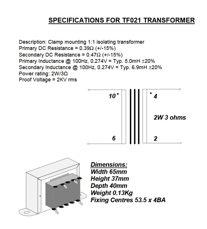
Transformer is 2W, 1:1, nominally 3 Ohm, but is good for 15 Ohm, 20Hz, which is well below what I'll be putting through it here.
EDIT: There appears to be an issue with some of the links to images below..... I'll try and sort it.
EDIT: Fixed it.....


Ash Small, Sat Nov 17 2018, 05:50PM
So, New information....
I've been doing a bit of online research, apparently, this topology, with the cap referenced to the source is generally called 'ultrafeed topology'. It has pro's and con's, the cons being about isolation..... in the case of failure of an O/T, the plate voltage is not isolated. That's not really an issue with a drain potential of 19V. It appeals to me because it defies the rules of the usual descriptors regarding voltage and current, it's effectively both. It doesn't really matter in which leg you place the cap, it's in series between them.
It also excels as an ungrounded low impedence source.
Anyway, back to the current question, regarding how 'isolated' this circuit needs to be. I've come to the conclusion after extensive googling that the issues regarding inadequate isolation all seem to relate to ground loop problems. That was my understanding when I designed it and that is why I chose the ultrafeed topology. I'm also aware that these were traditionally driven from O/T's running from tube stages. As the load is just an inductive load, like a transformer primary, I can't see that any more isolation would be required, although I do understand the meaning of 'total isolation', especially when related to safety and higher voltages. I propose to order a couple of small audio transformers for delivery on Tuesday, and then try my original circuit both with and without 'total isolation'. That would appear to be the most pragmatic approach, before I start building a long tailed pair, or H bridge, or something.
There is another isolation issue relating to power supply ripple rejection, but my power supply is completely ripple free.
In the meantime, I'll get on and build the recovery stage.....
I do plan to use the transformers for other purposes, one is ideal for driving a long tailed pair, the other for driving an H bridge. (It's likely that the power stage of an amp I'm building is likely to consist of a class A power JFET H bridge, with choke regulation. Something I've never seen attempted before
)Transformer is 2W, 1:1, nominally 3 Ohm, but is good for 15 Ohm, 20Hz, which is well below what I'll be putting through it here.
EDIT: There appears to be an issue with some of the links to images below..... I'll try and sort it.
EDIT: Fixed it.....


Re: Function and form....
Ash Small, Mon Nov 19 2018, 09:56PM
Here's the 'recovery' circuit.... the circuit that amplifies the output from the spring reverb tank back up to line level.....
I could leave out the input gate resistor and up to four capacitors, but as I'm testing it at the transistor voltage limits, they do add some protection in the case of transistor failure.
This circuit has yet to be tested, but is basically two of the boost stages that drives the output stage for the tank input.
More to come in due course.....

EDIT: The input cap and resistor form a high pass filter, although it currently passes pretty much everything, but could be 'tweaked' if required, also there's room on the left hand side of the board to add a low pass filter if this turns out to be required.....
Re: Function and form....
Shrad, Wed Dec 05 2018, 07:18AM
would I have known about the load, I wouldn't have told you about isolation :) the transformer is giving you that already so no real need of long tailed pair or anything, just DC blocking will be sufficient
I personally tried hooking up a PAM8403 module to a small toroïdal transformer to match a tube phase splitter, or even a PP stage directly, to avoid half the iron with replacing power supply by a PLC stage with a current limit... would have made nice, easy instrument amplifiers (please give me shares if you start a business on this idea ;) )
Re: Function and form....
Ash Small, Sat Jan 05 2019, 11:37PM
It works fine without the transformer. Once I got thinking I realised there was no good reason not to use one, although the only good reasons I could think of for using one is that the famous Fender units from the Sixties all had transformers, so maybe it was a part of the sound. Also, it was simpler to reverse the phase, which I did do. Phase shouldn't in theory be important in this application (reverb driver), but the waveforms seem to match better one way round. I'm still playing with it all, added active splitter and combiner, it's pumping 50mA or more, still playing with trimpots and cap values, and I need to add attenuation to the output.....
Ash Small, Sat Jan 05 2019, 11:37PM
Shrad wrote ...
would I have known about the load, I wouldn't have told you about isolation :) the transformer is giving you that already so no real need of long tailed pair or anything, just DC blocking will be sufficient
I personally tried hooking up a PAM8403 module to a small toroïdal transformer to match a tube phase splitter, or even a PP stage directly, to avoid half the iron with replacing power supply by a PLC stage with a current limit... would have made nice, easy instrument amplifiers (please give me shares if you start a business on this idea ;) )
It works fine without the transformer. Once I got thinking I realised there was no good reason not to use one, although the only good reasons I could think of for using one is that the famous Fender units from the Sixties all had transformers, so maybe it was a part of the sound. Also, it was simpler to reverse the phase, which I did do. Phase shouldn't in theory be important in this application (reverb driver), but the waveforms seem to match better one way round. I'm still playing with it all, added active splitter and combiner, it's pumping 50mA or more, still playing with trimpots and cap values, and I need to add attenuation to the output.....
Print this page