
World's Simplest Frequency Counter
Hazmatt_(The Underdog), Thu Nov 23 2006, 02:45AMThat's right. I have made a frequency counter so simple that anyone can put it together (or so I hope).
I needed a tachometer for a motor, and spent 3 weeks going through counter circuits that just did not work. Some of the circuits were untested designs, and some fed pulses into monostables that were too short for the monostable to trigger.
I have done away with monostable triggering, and I have designed a rock solid MSI Frequency counter that really works!
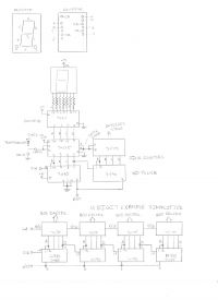
The first step is to setup the counter so that we can see if it will count up, reset and latch the displays. Here is an example using 74XX family logic gates to accomplish this.
I am showing the pinout for the display so you can hook one up. If you have a different type of display you can figure out the segments by using a continuity tester. The resistors should be about 220-330R each. Once you get the display hooked up to the 7447, test your display to see if it decodes properly by jumpering the BCD inputs to logic 1 or 0.
The next step is to get the latch connected. The latch is a quad D flip-flop that stores the old count, or is transparent depending on the latch enable bit. You should be able to jumper the BCD inputs, freeze the display, then change all the jumpers, and the number will stay until you change the latch state. How cool is that!
After this comes the decade counters. These divide the input so that you end up with decades for each digit. The D output spills over into the A input of the next counter, making a decade chain. The 7490 automatically resets itself after 9 to 0, but we need to be able to clear the count, so we trigger the master reset by pin 2. You will be able to count up while the latch is held at logic 1 and reset is at logic 0. Then you can reset the count, freeze the count, and play with it.
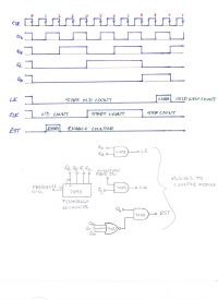
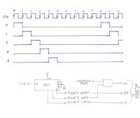
So the hard part is done right? Well, kind of. We need to generate the timing structure now. We need to arrange the gate, latch, and reset pulses such that we make a functional counter. I have given you the timing diagram for the sequency generator, another 7490 and a couple of gates. This is where the real 'magic' happens. This sequencer takes your standard timebase input and derives the necessary pulses to control your counter.
The last step of all of this is coming up with your standard. What standard should I use?
Well, if you needed a tachometer, you want the operator to see R.P.M right? And of course for a frequency counter you would want to see counts/ second.
I have set up the divider of 30,000 to divide my 2MHz source so I get 66.6666 Hz. This gives me my timing for the motor.
But likewise, if you wanted 100 Hz timebase for your counter, you could implement a 1MHz crystal or 10MHz crystal and divide it down in decades.
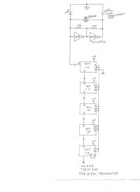
**There's a bit of a mistake on the divider chain. If you look at the last two chips it should be 12 output to 14 input. All dividers are 14 inputs from previous stage, and 12 as the output to the next stage. Hope that clears up any confustion**
This is a great little counter. It will function up to about 40MHz. AND you can add as many digits to the right as you need. Anything more then 8 digits is really un-necessary, but I thought I might like to make a 20 digit counter someday for fun.
The next evolution of this counter is to take it from overly bulky 74XX logic and go full CMOS.
The CD 4026 Decade/latch/decoder replaces the 7490/7475/7447 ALL IN ONE!!!!! How cool is that!
So that will reduce the counter module to 4 chips and 4 displays right off.
Then if you take the 4017 and derive the timing pulses from it, any 3 you like, you have again your timing for latch, reset, and gate. So that will reduce the 'magic gating' even further.
And still yet, if you can find a crystal that matches up with a large 2^n divider chip, you could derive your timebase in the smallest number of chips possible.
A word of caution to builders: This circuit performs perfectly, but be careful about power supply noise. This may be an issue in your circuit. If you're like me, and you built your own regulated power supply, be aware that it may be switching at very high frequencies well in the hundreds of KHz. So if you get some strange results, like the display jitters quickly, that means you are seeing the result of high frequency rail noise.
It took me a while to track my noise down, and it was very high frequency. So I switched to a simple regulated supply unit by Interplex Enterprises. They make a little regulated supply that plugs into breadboards. This supply uses a 7805 and worked fine.
My supply still needs some rework, and that will come later.
Have fun.
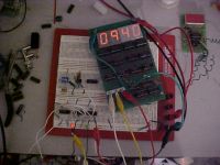
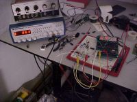
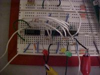
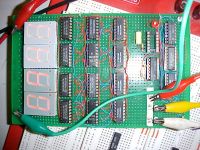
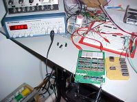
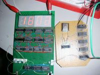
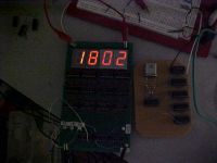
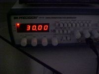
Some more old pics showing it working:

Pics of my Tachometer for my DCRSGC
Re: World's Simplest Frequency Counter
ragnar, Thu Nov 23 2006, 02:50AM
Hooray! I've been looking forward to this, thanks Hazmatt. =)
ragnar, Thu Nov 23 2006, 02:50AM
Hooray! I've been looking forward to this, thanks Hazmatt. =)
Re: World's Simplest Frequency Counter
Hazmatt_(The Underdog), Thu Nov 23 2006, 03:12AM
You're very welcome. I hope to see lots and lots of variants of my design. AND I will be expecting to see some 12 Digit counters from you guys
This circuit is fine up to 100Hz into the timebase generator, and with 8 digits, that gives you one heck of a counter!
I will have to see what I can do about microwave mixing down converters so you guys can have 4GHz counters. Now wouldn't that be fun!
If there is any debate of the timing diagram that I made some errors on the margins passed 0 to the left and after 0 on the right, don't worry. All we're interested in are the timing pulses from 0 to 0 in the full cycle, okay
Happy building and Measuring!
Hazmatt_(The Underdog), Thu Nov 23 2006, 03:12AM
You're very welcome. I hope to see lots and lots of variants of my design. AND I will be expecting to see some 12 Digit counters from you guys

This circuit is fine up to 100Hz into the timebase generator, and with 8 digits, that gives you one heck of a counter!
I will have to see what I can do about microwave mixing down converters so you guys can have 4GHz counters. Now wouldn't that be fun!
If there is any debate of the timing diagram that I made some errors on the margins passed 0 to the left and after 0 on the right, don't worry. All we're interested in are the timing pulses from 0 to 0 in the full cycle, okay

Happy building and Measuring!
Re: World's Simplest Frequency Counter
Steve Conner, Thu Nov 23 2006, 11:13AM
Nice work Hazmatt! Here's a thought: can you (or anyone else) figure out how to make it into a speed trap that reads out in meters per second (or fps or whatever) without losing the frequency counter function? A dual-purpose frequency counter and speed trap would be a great gizmo for coilgunners.
You get prescaler ICs for a few dollars that let these counters read up into the GHz.
Steve Conner, Thu Nov 23 2006, 11:13AM
Nice work Hazmatt!
 Here's a thought: can you (or anyone else) figure out how to make it into a speed trap that reads out in meters per second (or fps or whatever) without losing the frequency counter function? A dual-purpose frequency counter and speed trap would be a great gizmo for coilgunners.
You get prescaler ICs for a few dollars that let these counters read up into the GHz.

Re: World's Simplest Frequency Counter
Hazmatt_(The Underdog), Thu Nov 23 2006, 07:20PM
For a speed trap you would disengage the reset and make it a manual reset. Then you would need a rising edge trigger as the start count, and a falling edge trigger as the stop count. Inbetween the count trigger, the local oscillator timebase would free-run. You might be able to do both with the same counter, but you will need sets of latches to store the data until you can read it out on the display.
I did buy way back when, some Motorola prescalers that go to 1.2 GHz for $14 each! I had planned back in '98 to build an 8 digit counter and generator, but never got to it. I still have the ICM7216DIPI, and a zif socket for it.
I'm going to post the Dulux version of the counter soon too, All CMOS.
Matt
Re: World's Simplest Frequency Counter
Sulaiman, Fri Nov 24 2006, 09:59AM
Nicely done project.
I have built parts of two frequency counters many years ago
One was VERY similar using 7490 etc. etc.
One used a 4 decade counter with 7-segment multiplexed drive ic
I never finished the hardware, enclosure, knobs, display window etc.
I bought an 80 MHz Philips frequency meter for about GBP15 from eBay
and a Racal Nixie computing Counter/Timer with ext. START/STOP for about the same
(the 5/6 decade counter board used 7490 + latches + decoders + nixies)
So for readers looking to learn, DIY is excellent
If you just want a timer/counter it's MUCH cheaper/quicker/easier to get a cheap one off eBay.
Re: World's Simplest Frequency Counter
Steve Conner, Fri Nov 24 2006, 12:13PM
I still use an old nixie-tube frequency counter that I dumpster-dived years ago, so I kind of agree with Sulaiman's view there. But this is an excellent project for learning about all those textbook principles of digital electronics. I see hazmatt already learnt the "Never use monostables" rule the hard way

Re: World's Simplest Frequency Counter
Dr. Slack, Sat Nov 25 2006, 08:45AM
Absolutely. However, if you want a timer/counter that you can control, read, log and has extremely high resolution, then a program that uses your PC soundcard is a very easy and cheap way of doing it. I wrote one in Matlab, which reads 1000 samples from the sound card, fits the demodulated phase, then differentiaites it, which gives a noise-limited resolution in parts per billion ( don't count zero crossings, or look for the peak of an FFT, neither are in the same ball-park for resolution ). That resolution allows you to prescale your input frequency down to the 5-15kHz needed for the sound card, and still get useable resolution at UHF or even microwave input frequencies. Accuracy is down to the stability of your soundcard timebase, however it's easy enough to use the second channel to measure the frequency of a divided down reference source (10MHz oscillator, or the carrier from a designated radio station) if you are fussed about stability, and essentially the sound card does a comparison between the two.
My application was measuring the output of a differential capacitive oscillator transducer, so comparing two channels needs only resolution, not accuracy or stability.
Dr. Slack, Sat Nov 25 2006, 08:45AM
If you just want a timer/counter it's MUCH cheaper/quicker/easier to get a cheap one off eBay.
Absolutely. However, if you want a timer/counter that you can control, read, log and has extremely high resolution, then a program that uses your PC soundcard is a very easy and cheap way of doing it. I wrote one in Matlab, which reads 1000 samples from the sound card, fits the demodulated phase, then differentiaites it, which gives a noise-limited resolution in parts per billion ( don't count zero crossings, or look for the peak of an FFT, neither are in the same ball-park for resolution ). That resolution allows you to prescale your input frequency down to the 5-15kHz needed for the sound card, and still get useable resolution at UHF or even microwave input frequencies. Accuracy is down to the stability of your soundcard timebase, however it's easy enough to use the second channel to measure the frequency of a divided down reference source (10MHz oscillator, or the carrier from a designated radio station) if you are fussed about stability, and essentially the sound card does a comparison between the two.
My application was measuring the output of a differential capacitive oscillator transducer, so comparing two channels needs only resolution, not accuracy or stability.
Re: World's Simplest Frequency Counter
Hazmatt_(The Underdog), Sun Nov 26 2006, 01:02AM
Here is a very simple timebase generator for your counter. It uses the 4017 to generate the pulses. You can reset on pulse 5, but letting it go through its full count cycle will give you more display time, so it will appear to be more stable.
I was going to add the 4026 as your decade counter/display driver/latch, but it occured to me that the 4026 does not have a latch to 'store' the count. It can blank the display to save power, or force the display to all zeros, but no D flip-flops for storage.
Alternativily there are two chips that do a rather nice job for 3 displays. They are the 4511 and 4553. They come with a 3 digit up counter kit that you can chain together for n x 3 digit counter modules. So you could have a 9 digit frequency counter if you desired. I will post that circuit a bit later.

Re: World's Simplest Frequency Counter
Hazmatt_(The Underdog), Sat Jun 08 2013, 01:31AM
Now here is an ancient thread indeed!
But we come back to it with purpose, and a real application!
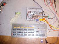
The picture is the counter connected to a VCO source system in the Aluminium box. The counter is not fully hooked up, if it were, there would be 6 digits reading out, but for test, all I needed was 3 digits.
The picture is showing 300, but.. 300 of what, hehehe.
That's not 300 KHz, 30.0 MHz, or even 300 MHz, its counting from the VCO 3000 MHz !!!!!!! NOW HOW COOL IS THAT!
The box is furnished with a Minicircuits ZX95-2800-S+, which feeds a microwave splitter, to a small +20 dB gain block, and to a divider chain.
The divider chain divides by 160, and feeds a buffer pulse amp so the TTL can see what is coming out, roughly 19 MHz max.
This then feeds the 6 digit counter system, with a 250 Hz clock, which offsets the 160 divde prescalar of my little 'magic box'.
Top that off with a selectable attenuator that is to come later, throw it in a neat little box, and you have yourself a frequency source
that spans 1240 MHz to 3000 MHz, with a max power out of +20 dBm!

Re: World's Simplest Frequency Counter
Tetris, Mon Jun 10 2013, 12:20AM
Isn't (technically) the world's simplest frequency counter a crystal?
Tetris, Mon Jun 10 2013, 12:20AM
Isn't (technically) the world's simplest frequency counter a crystal?
Re: World's Simplest Frequency Counter
Dr. Slack, Mon Jun 10 2013, 07:00AM
And how would you use a crystal as a frequency counter? Stare into it in a darkened room chanting 'Ommmm' and have the frequency come to you in a vision? I never did like the use of the the word 'technically', especially when my wife uses it, to mean 'please excuse me while I spout bollox'.
Dr. Slack, Mon Jun 10 2013, 07:00AM
ASHPoD wrote ...
Isn't (technically) the world's simplest frequency counter a crystal?
Isn't (technically) the world's simplest frequency counter a crystal?
And how would you use a crystal as a frequency counter? Stare into it in a darkened room chanting 'Ommmm' and have the frequency come to you in a vision? I never did like the use of the the word 'technically', especially when my wife uses it, to mean 'please excuse me while I spout bollox'.
Re: World's Simplest Frequency Counter
Hazmatt_(The Underdog), Mon Jun 10 2013, 01:22PM
I was wondering the same thing, although I was going to say it in a different, less harsh way:
"A crystal as a frequency counter? Please justify your reasoning."
I think what was intended, because I was blindsided by this statement as well, was that a simplistic frequency counter is a BFO, although it wasn't said that way.
Beat Frequency counting, or harmonically mixing would be "simple" compared to a digital counter, BUT! and this is a big BUT!, you STILL need to have done alignments on the BFO BEFORE you can even start to use it! Which means you again need a calibrated source and some kind of meter, standard, or reference.
I have a BFO test set for TV service, a Simpson Genescope, which is a monster with AM and FM generators. Part of the TV alignment process is tuning the TV with the Genescope and getting a beat pattern on the CRO, then taking a dial reading (wich is already calibrated in Megacycles), and doing a calculation.
Failing that, if you wanted to be humorous, or an attempt at humor would have been to show a "reed type" frequency meter and call it a day. But that is not productive, nor relavent to forwarding the cause of this thread.
Re: World's Simplest Frequency Counter
Hazmatt_(The Underdog), Sat Jul 13 2013, 06:34PM
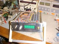
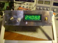
Here we have the counter married to a VCO, and is now a portable microwave signal source, nearly complete, it just needs the stickers made up and it will be finished.
Hazmatt_(The Underdog), Sat Jul 13 2013, 06:34PM
Here we have the counter married to a VCO, and is now a portable microwave signal source, nearly complete, it just needs the stickers made up and it will be finished.


Re: World's Simplest Frequency Counter
Linas, Sat Jul 13 2013, 06:39PM
why not implement that on simple FPGA/CPLD? that should be very easy, with low wires count...
Linas, Sat Jul 13 2013, 06:39PM
why not implement that on simple FPGA/CPLD? that should be very easy, with low wires count...
Re: World's Simplest Frequency Counter
Hazmatt_(The Underdog), Sun Jul 14 2013, 08:55PM
1. Frequency out of the prescalar is 18.75 MHz max
2. Didn't have a week to play with code, I work full time.
3. I knew this way would work
4. I designed this frequency counter arrangement, so why not use it.
5. All parts are field replacable, a programed chip is not.
Print this page