
Tuned loop for AM broadcast reception
klugesmith, Fri Sept 22 2017, 12:46AMYears ago, I made a loop antenna configured much like the one described at

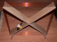
My tuning capacitor, like Darrin's, is a good old 365 pF variable unit with air between the plates. The most obvious difference: my coil form is just a flat, square cardboard box. The widely spaced turns of wire rest on the four narrow faces of the box, secured with sticky tape of some kind.
A better word would be rested, because the tape has dried up and the turns are falling off. Not yet tangled beyond recovery, but close.
I want to repair or rebuild this and connect a much larger capacitor, to tune for the national time-of-day station WWVB at 60 kHz.
Came here to shamelessly ask, at a forum, about the space between turns. Why not pack the turns closely together, as if one were making a degaussing coil? My guess is to keep the self-capacitance down, and to some extent the inductance, so the Self Resonant Frequency is well above the band of interest.
A hula hoop would make a handy loop-antenna enclosure, but I don't see an easy way to keep wire turns away from each other if they run inside the plastic tube.
Re: Tuned loop for AM broadcast reception
Dr. Slack, Fri Sept 22 2017, 06:30AM
A while ago I did a bit of head-banging about what influences coil self capacitance, and how to keep it down, starting with the fact that TC secondary calculators seem to give a self capacitance that depends on overall geometry rather than wire and turn-spacing details.
The lightbulb moment was when I found a reference that suggested computing the energy stored when the coil was at peak volts, and then using this to define an effective capacitance. This weights any pair of turns with the square of the voltage between them. What this quickly leads to is that it's not the adjacent inter-turn effects that are important, which it might appear that basket wound coils reduce, but it's the input to output layers and their polarity where you get the most bang for buck, which is what pancake windings are doing. The implication being that for single layer coils, the turn spacing is of much lower importance than the fact that you have a single layer.
I'm not trying to teach you to suck eggs, o granny, but just trying to help other readers understand what's important in the geometry of the coil.
I notice your X-shaped coil is single layer, kept that way by the former. A winding in a hula-hoop would of necessity be multi-layer, so regardless of the turn spacing, the self capacitance would be higher. If you want to wind the coil within the cross section of a hula hoop, and rate the SRF from the best to the worst configuration, most of the benefit will be had by, and in this order, for keeping it in layers ordered from one end to the other, then with the same layer polarity, then with good inter-layer spacing, and finally with good inter-turn spacing. Of course that doesn't make it any easier to compute from geometry and first principles.
If you start with an unloaded coil, it will have a particular SRF. As you increase the external capacitance, the loaded resonant frequency will fall with respect to the unloaded SRF. With a large enough external C, the spacing between the two can be made very large. How large is 'large enough' for any given receiver configuration?
It's long been an amusing thought experiment of mine to make a coil by using a length of flat N-way ribbon cable, soldered in a loop 'off by one', so there's a single conductor looping N times round. This would enforce a single layer geometry and stay flat as long as not forcibly scrunched up.
I must confess I've not figured out or found in a search the scaling laws for SRF of a coil as you increase turns, cross section or diameter, but then I've not applied myself seriously to that yet. These would allow you to perform a small-scale experiment and estimate what a larger hula hoop based coil would do, to see whether scramble wound would be 'good enough'. It's complicated by practical assumptions. Even something as simple as 'for constant cross section and diameter, how does changing the number of turns affect self capacitance?' cannot neglect the fact that inter-layer distance tends to be constant (wire insulation and tape) while wire diameter varies. I'll need to think about that.
I'm not sure yet how you intend to wind a coil inside a hula hoop? Perhaps cut a slot round the outside and simply wind into the former. This would at least achieve a gross input to output ordering, though not really layers. Pulling the wire through again and again with an increasing coil building up seems like awfully hard work, and would still leave an open bit of the hoop, and would probably randomise any hint of 'layer ordering' that you might have wanted to instill. Winding through an outer slot might be improved if for some reason you didn't need to fill the entire cross section with wire, so you wound wire and string together. This would 'bulk up' the winding and increase the inter turn and 'inter layer' spacing, so should reduce self capacitance.
Re: Tuned loop for AM broadcast reception
Sulaiman, Fri Sept 22 2017, 10:58AM
For a single layer coil, the inter-turn capacitance is not usually critical as it is of moderately high 'Q'
it is the proximity effect causing an increase in the effective resistance of the wires I find significant,
a winding pitch of 3x wire diameter is a good balance between
'loss' of effective wire csa (increase in resistive loss) versus good inter-turn magnetic coupling to maximise inductance.
There are online calculators giving effective height, Q and impedance ... somewhere.
For 60 kHz (wavelength=5km) there are three options that I would consider;
1) An electrostatically shielded ferrite rod 'loopstick'
SNR should be good enough for electronic amplification to compensate for antenna gain,
and the antenna can easily be rotated to null out the strongest source of interference.
This is the prefered commercial solution, using ferrite rods of one to three inches long.
Longer = better.
2) Multi-turn loop.
Received signal is proportional to Area x #Turns .... wire length.
You can choose a small area with lots of turns - easy to rotate but difficult to get high 'Q'
or a large area with few turns for better 'Q' but at the expense of rotatability, portability and storage.
The loop needs to be vertical, well clear of earth, and aligned to the transmitter.
A single-turn pickup loop in the ventre of the main tuning coil can be used to supply a lower impedance (e.g. 300 Ohm ladder) cable and amplifier.
3) A vertical whip, as tall as possible, plus earth. (I use 2nd-hand fishing poles)
The whip impedance will be high (e.g. 10m is only 1/500 wavelength) so 'earthing' impedance can be high too.
This will be omnidirectional and wideband and very noisy, requiring significant filtering.
but allows 'messing about' at other frequencies.
(e.g. audio frequencies, or make it 1/4-wavelength at shortwave frequencies of interest - good 'earth' required)
Re: Tuned loop for AM broadcast reception
Chris Russell, Sat Sept 23 2017, 07:38PM
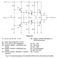
Not to get too far off topic, but as a fourth option at 60kHz, a short whip with a high input impedance amplifier also works very well. PA0RDT's active whip design works well here, but I've had even better luck with one of the Trask designs, which basically uses a complementary pair of JFETs in push-pull, followed by a second push-pull stage of complementary Darlington BJT pairs. Reception on 60kHz is strong, but of course I'm only one state over from WWVB. VLF transmitters around 24kHz in Hawaii, North Dakota, and Maine are all readily receivable as well.
Still, if the goal is to receive WWVB and only WWVB, it's hard to beat a portable tuned loop or loopstick, if only for their rejection of AM broadcast interference, and the ability to rotate to null out local noise sources.
Edit: note that there's a mistake in the parts list. Q3 and Q4's descriptions should be swapped. Their appearance in the schematic is correct.
Chris Russell, Sat Sept 23 2017, 07:38PM
Not to get too far off topic, but as a fourth option at 60kHz, a short whip with a high input impedance amplifier also works very well. PA0RDT's active whip design works well here, but I've had even better luck with one of the Trask designs, which basically uses a complementary pair of JFETs in push-pull, followed by a second push-pull stage of complementary Darlington BJT pairs. Reception on 60kHz is strong, but of course I'm only one state over from WWVB. VLF transmitters around 24kHz in Hawaii, North Dakota, and Maine are all readily receivable as well.

Still, if the goal is to receive WWVB and only WWVB, it's hard to beat a portable tuned loop or loopstick, if only for their rejection of AM broadcast interference, and the ability to rotate to null out local noise sources.
Edit: note that there's a mistake in the parts list. Q3 and Q4's descriptions should be swapped. Their appearance in the schematic is correct.
Re: Tuned loop for AM broadcast reception
Sulaiman, Sun Sept 24 2017, 12:06AM
Why not just use an LM833 (or newer, better) op-amp ?
The discrete jFET front end would be noisier.
Sulaiman, Sun Sept 24 2017, 12:06AM
Why not just use an LM833 (or newer, better) op-amp ?
The discrete jFET front end would be noisier.
Re: Tuned loop for AM broadcast reception
Chris Russell, Sun Sept 24 2017, 06:21AM
Mostly because the folks turning out well-documented, usable, builder-tested designs with measured IMD, OIP2, and OIP3 characteristics are still using discretes, unfortunately. It's one of the problems Amateur radio is facing: the older "Elmers" are not on the bleeding edge, and those that are on the bleeding edge tend not to be Elmers.
I'm sure there's better silicon out there, but if there are any designs for VLF to VHF active whip amplifiers with extremely good performance characteristics, I haven't seen them, and don't have the time/equipment/expertise to design and test them myself. Regardless, across the VLF and LF spectrum, atmospheric (and man-made) noise is, by far, the limiting factor.
For just receiving one LF frequency, though, I'm sure it wouldn't be hard to put something together with easier-to-source parts that would work well enough.
Re: Tuned loop for AM broadcast reception
Plasma, Mon Sept 25 2017, 05:36AM
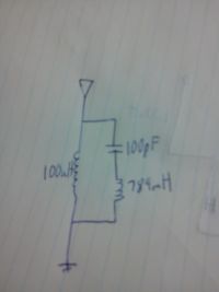
Kludgesmith you might be able to do something like below, saving the area of a large antenna,, might be off track with what you mean
Plasma, Mon Sept 25 2017, 05:36AM
Kludgesmith you might be able to do something like below, saving the area of a large antenna,, might be off track with what you mean

Re: Tuned loop for AM broadcast reception
Carbon_Rod, Mon Sept 25 2017, 06:25AM
You may also find some interesting designs here:

Carbon_Rod, Mon Sept 25 2017, 06:25AM
You may also find some interesting designs here:

Re: Tuned loop for AM broadcast reception
Sulaiman, Mon Sept 25 2017, 08:48AM
Carbon_Rod - Great link ... Thanks.
.......................................... .......
Chris Russell, an op-amp such as the LM833 that I mentioned would be good at 60 kHz but useless at VHF.
(the amlifier that you showed looks excellent for up to VHF, but would be overkill here)
This application of an op-amp specifically at 60 kHz should be simple for 4HV members to implement, basic application notes and 'standard' op-amp topologies, the LM833 is pin-compatible with most dual 8-pin dip op-amps, just a little faster and quieter
there is no need to measure r.f. parameters
....................................... ..............
I agree with Chris Russell that a short whip is as good as a long one when there is a lot of emi and noise,
i.e. the SNR will not be significantly worsened by amplifier noise.
(but I work in a shed with external antennas and I prefer a longer whip / larger signal / less amplification)
I have found that a parallel tuned circuit at the bottom of a short whip is best,
the inductor shunts accidental d.c. and low frequencies directly to earth,
and the capacitor does the same for very high frequencies
and of course at the intended resonant frequency it is a tuned circuit that can be tapped for a low impedance amplifier, or fed directly (via protection) to a high impedance amplifier.
(allow for c10 pF/m whip capacitance ... from memory, but like TCs, a nearby hand adds significant capacitance)
I failed to get a good signal from my 'local' MSF 60 kHz, 75 kW erp at c276 km range, time transmitter, when using a whip in my shed, due to noise and insufficient shielding and filtering.
So I still think that a ferrite rod loopstick is best - unless you WANT a huge antenna)
(due to my location I mostly use Radio4 198 kHz as a reference)
OR, you could cheat, and buy a radio 'atomic' clock and tap off a signal, e.g. ?
?
......................................
Plasma, I don't understand the functioning of your circuit, could you elaborate ?
Sulaiman, Mon Sept 25 2017, 08:48AM
Carbon_Rod - Great link ... Thanks.
.......................................... .......
Chris Russell, an op-amp such as the LM833 that I mentioned would be good at 60 kHz but useless at VHF.
(the amlifier that you showed looks excellent for up to VHF, but would be overkill here)
This application of an op-amp specifically at 60 kHz should be simple for 4HV members to implement, basic application notes and 'standard' op-amp topologies, the LM833 is pin-compatible with most dual 8-pin dip op-amps, just a little faster and quieter
there is no need to measure r.f. parameters
....................................... ..............
I agree with Chris Russell that a short whip is as good as a long one when there is a lot of emi and noise,
i.e. the SNR will not be significantly worsened by amplifier noise.
(but I work in a shed with external antennas and I prefer a longer whip / larger signal / less amplification)
I have found that a parallel tuned circuit at the bottom of a short whip is best,
the inductor shunts accidental d.c. and low frequencies directly to earth,
and the capacitor does the same for very high frequencies
and of course at the intended resonant frequency it is a tuned circuit that can be tapped for a low impedance amplifier, or fed directly (via protection) to a high impedance amplifier.
(allow for c10 pF/m whip capacitance ... from memory, but like TCs, a nearby hand adds significant capacitance)
I failed to get a good signal from my 'local' MSF 60 kHz, 75 kW erp at c276 km range, time transmitter, when using a whip in my shed, due to noise and insufficient shielding and filtering.
So I still think that a ferrite rod loopstick is best - unless you WANT a huge antenna)
(due to my location I mostly use Radio4 198 kHz as a reference)
OR, you could cheat, and buy a radio 'atomic' clock and tap off a signal, e.g.
 ?
?......................................
Plasma, I don't understand the functioning of your circuit, could you elaborate ?
Re: Tuned loop for AM broadcast reception
Chris Russell, Mon Sept 25 2017, 10:48AM
Sulaiman, my only caveat with not worrying too much about RF parameters would be to ensure that the circuit's response rolls off strongly not too far above 60kHz, so that MW broadcast intermodulation products don't become an issue. The 10kHz channel spacing unfortunately tends to place intermodulation products at nice round spots on the dial, often every 10kHz all the way up and down the band for quite a ways, if there are multiple strong stations nearby.
Personally, I'd also go for the loopstick. Ferrite bars are easily scrounged or found cheaply online. Loopsticks are easy to place in a waterproof enclosure made from PVC or ABS pipe, placed far away from noise sources and oriented for best reception, and even then remotely trimmed via varactor (or reverse-biased LED, in a pinch) if a little wiggle room is desired.
Re: Tuned loop for AM broadcast reception
Conundrum, Mon Oct 02 2017, 06:25AM
What about using the glass from dead Samsung phones as it has a graphite backing with good electromagnetic properties similar to a super-ferrite rod!
Its a minor hassle to get these out and all it would need is some thin clear parcel tape to hold the glass together (I used S6) then use a printer coil former.
Limitless quantity of these so you could make a huge antenna this way.
Also it does not by any means need to be new wire, wire salvaged from an old relay would work fine.
I did this for my recent coil and it works very well indeed.
Alternate *3, take the graphene layer off the screens with parcel tape and wind it round the former.
4 layers with thin enough tape should work fine and be about 1/10 the weight of a ferrite rod but so much larger.
Re: Tuned loop for AM broadcast reception
Proud Mary, Wed Oct 11 2017, 02:26PM
Chris Trask, mentioned by Mr Russell, does have some really good designs for a varactor tuned mag loop, and a broadband mag loop, where great attention is paid to matching the very lo-Z| loop to the feeder.


Proud Mary, Wed Oct 11 2017, 02:26PM
Chris Trask, mentioned by Mr Russell, does have some really good designs for a varactor tuned mag loop, and a broadband mag loop, where great attention is paid to matching the very lo-Z| loop to the feeder.


Re: Tuned loop for AM broadcast reception
Conundrum, Sun Oct 15 2017, 06:44AM
making progress.
Apart from laboriously making Litz wire *by hand* can someone suggest a source?
I found that old microwave transformers and some TVs have Litz primaries but
normally they are glued together.
Conundrum, Sun Oct 15 2017, 06:44AM
making progress.
Apart from laboriously making Litz wire *by hand* can someone suggest a source?
I found that old microwave transformers and some TVs have Litz primaries but
normally they are glued together.
Re: Tuned loop for AM broadcast reception
klugesmith, Sun Mar 11 2018, 07:39AM
Don't know if this should go on Projects forum.
I'm about to make a new loop antenna, using a laminated wooden hoop as a form.
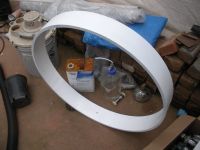
The hoop is wound from four turns of white-surfaced hardboard about 1/8" (3 mm) thick. The material is heavy and not very strong, flexible, or water-tolerant. I foolishly bought a sheet 'cause it was on clearance, for less than $4. Mostly bonded with polyurethane construction adhesive, from a large caulking-gun tube.
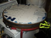
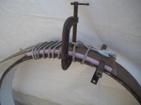
You may have seen the round form here: At the beginning and end, I tapered the material and stuck it down with water-based wood glue.
klugesmith, Sun Mar 11 2018, 07:39AM
Don't know if this should go on Projects forum.
I'm about to make a new loop antenna, using a laminated wooden hoop as a form.

The hoop is wound from four turns of white-surfaced hardboard about 1/8" (3 mm) thick.
 The material is heavy and not very strong, flexible, or water-tolerant. I foolishly bought a sheet 'cause it was on clearance, for less than $4. Mostly bonded with polyurethane construction adhesive, from a large caulking-gun tube.
You may have seen the round form here:
 At the beginning and end, I tapered the material and stuck it down with water-based wood glue.
Re: Tuned loop for AM broadcast reception
Conundrum, Sun Mar 11 2018, 08:10AM
Might have a go at this now some nice person on 4HV sent me some.
Hint: if you're linking sections of wire, try and make more than one connection. 8 seems to be the minimum but each one reduces overall noise and increases Q.
Also relevant, I can probably track down a few ferrite rods here if you wanted to make an all-ferrite coil. Just be sure to leave a gap in the foil shield!
Also relevant, try and use high silver content (Ag) solder if possible as though somewhat toxic it does work well for RF applications.
SnAgCu is adequate but sucks only slightly less than 60/40.
Re: Tuned loop for AM broadcast reception
klugesmith, Mon Mar 26 2018, 05:05PM
Had an opportunity to measure the old rectangular loop on a digitally-controlled LCR bridge.
For f=75 kHz on up, wrote down the vector impedance magnitude and angle.
Charted here, next to similar measurements on a compact toroidal inductor that might become used as a current transformer.
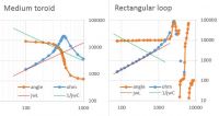
Vertical axis labels for angle, -180° to +180° linear, were cut off by the snip. H axis is f in kHz.
The toroid chart looks like textbook picture of L with parasitic C in parallel.
At low frequencies, with angle near +90°, it matches a 2.3 mH inductor (red line).
At high frequencies, with angle near -90°, it’s like a 52 pF capacitor (green line), if my arithmetic is right.
Self resonant frequency is 462 kHz; the angle reading is a sensitive indicator of that.
The loop chart has low frequency asymptote matching 558 uH inductor (red line). This time the green line is a hypothetical 126 pF capacitor to resonate with the coil at 600 kHz. Starting in the low MHz, we see wild excursions of the impedance. I think from various resonances in the 21-turn coil due to irregular spacing, after half the turns had literally fallen off the form and only roughly been put back in place.
With that much data, it was time to sacrifice the old coil and use its wire on a nice new form. Perimeter length is about the same, but it’s round so it encloses a larger area. The stubby solenoid's length and turn spacing (6 per inch) match the original rectangle.
The wire transplant was done while watching neighbor's dog, and watching Get Out on their big TV. By good luck, the old wire filled the form with about the same about left over at the finish; length per turn matched within 1%!
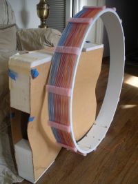
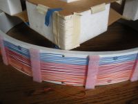
The turn spacers are blocks of plastic foam, each with 21 slots cut by knife.
klugesmith, Mon Mar 26 2018, 05:05PM
Had an opportunity to measure the old rectangular loop on a digitally-controlled LCR bridge.
For f=75 kHz on up, wrote down the vector impedance magnitude and angle.
Charted here, next to similar measurements on a compact toroidal inductor that might become used as a current transformer.

Vertical axis labels for angle, -180° to +180° linear, were cut off by the snip. H axis is f in kHz.
The toroid chart looks like textbook picture of L with parasitic C in parallel.
At low frequencies, with angle near +90°, it matches a 2.3 mH inductor (red line).
At high frequencies, with angle near -90°, it’s like a 52 pF capacitor (green line), if my arithmetic is right.
Self resonant frequency is 462 kHz; the angle reading is a sensitive indicator of that.
The loop chart has low frequency asymptote matching 558 uH inductor (red line). This time the green line is a hypothetical 126 pF capacitor to resonate with the coil at 600 kHz. Starting in the low MHz, we see wild excursions of the impedance. I think from various resonances in the 21-turn coil due to irregular spacing, after half the turns had literally fallen off the form and only roughly been put back in place.
With that much data, it was time to sacrifice the old coil and use its wire on a nice new form. Perimeter length is about the same, but it’s round so it encloses a larger area. The stubby solenoid's length and turn spacing (6 per inch) match the original rectangle.
The wire transplant was done while watching neighbor's dog, and watching Get Out on their big TV. By good luck, the old wire filled the form with about the same about left over at the finish; length per turn matched within 1%!


The turn spacers are blocks of plastic foam, each with 21 slots cut by knife.
Re: Tuned loop for AM broadcast reception
Conundrum, Tue Mar 27 2018, 06:10AM
Nice!
Wonder if anyone else has used zrzsg's graphene (aka heatsink graphite from phones) to make DIY RF antennas?
Mine seemed to work well and extended range on NFC, for lower frequencies it should be even better.
Conundrum, Tue Mar 27 2018, 06:10AM
Nice!
Wonder if anyone else has used zrzsg's graphene (aka heatsink graphite from phones) to make DIY RF antennas?
Mine seemed to work well and extended range on NFC, for lower frequencies it should be even better.
Re: Tuned loop for AM broadcast reception
klugesmith, Fri Mar 30 2018, 02:59AM
Does anyone else like the round coil's simple wooden stand?
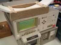
Today's vector impedance sweep shows an inductance of 614 uH. That's 10% higher than the old rectangular coil, which had the same turns count, wire length per turn, and wire spacing.
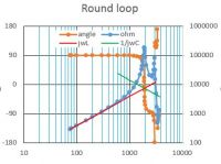
At the high end there's now a nice simple self-resonance at 1.92 MHz, indicating effective C of about 11.2 pF. Then the complex numbers stop behaving simply, just as with the old coil.
The coil was good at detecting me. At 1.92 MHz the angle reading was -5° with me sitting on a chair, close enough to push buttons. With one hand up near center of coil, angle went up to +60°. With me standing as far away as I could still read the display, angle was -14°.
Looks like the resonant C value for 60 kHz (WWVB) would be around 11.5 nF.
I figure that for AM broadcast band, this coil wants C adjustable between 16 and 140 pF. To make the most of the old 365 pF tuning capacitor, how about tapping the coil for reduced inductance, with the remaining turns left in place?
klugesmith, Fri Mar 30 2018, 02:59AM
Does anyone else like the round coil's simple wooden stand?

Today's vector impedance sweep shows an inductance of 614 uH. That's 10% higher than the old rectangular coil, which had the same turns count, wire length per turn, and wire spacing.

At the high end there's now a nice simple self-resonance at 1.92 MHz, indicating effective C of about 11.2 pF. Then the complex numbers stop behaving simply, just as with the old coil.
The coil was good at detecting me.
 At 1.92 MHz the angle reading was -5° with me sitting on a chair, close enough to push buttons. With one hand up near center of coil, angle went up to +60°. With me standing as far away as I could still read the display, angle was -14°.
Looks like the resonant C value for 60 kHz (WWVB) would be around 11.5 nF.
I figure that for AM broadcast band, this coil wants C adjustable between 16 and 140 pF. To make the most of the old 365 pF tuning capacitor, how about tapping the coil for reduced inductance, with the remaining turns left in place?
Re: Tuned loop for AM broadcast reception
Sulaiman, Fri Mar 30 2018, 11:44AM
I think that your coil is probably even better than measured - so close to earthed metal
Sulaiman, Fri Mar 30 2018, 11:44AM
I think that your coil is probably even better than measured - so close to earthed metal

Print this page