High frequency ZVS driver with low heat waste
Yunus, Sun Sept 17 2017, 01:45PMHi, i am a new member on this forum.
I am trying to build an ZVS driver to powering up the ferrite transformer.
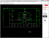
The circuit schema is attached below.
The problem is when i attached the little transformer, it cannot handle huge load,
the transformer getting hot quickly.
I tried increasing the frequency (lowering the capacitor), the transformer temperature drop a bit but the mosfet getting hot.
(i am not using heatsink because it is bulky, the circuit must fit into small casing.
I also tried using bigger transformer, the temperature both transformer and mosfets are pretty cool,
but i am not satisfied with the bulky size transformer.
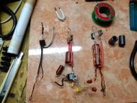
The transformer inductances are about 200 uH, 350 uH, 700 uH.
The inductance values is not by measurement (i don't have a tool to measure it).
Just the calculation from the page: http://coil32.net/online-calculators/ferrite-torroid-calculator.html.
The capacitor values are: some of 100 nF, some of 470 nF (i tried combination of parallel & series)
* frequency is about 15-80 KHz (the mosfet getting hot above 40 KHz)
* mosfet type is IRF540.
* ferrite cores are taken from VGA cable.
* power consumption is 12 V, 1,5-3 ampere.
Do you have an idea to build ZVC driver - small transformer - high power capacity.


Re: High frequency ZVS driver with low heat waste
hen918, Sun Sept 17 2017, 02:36PM
What are you making it for?
The first thing to do is find better ferrite. Chokes are designed to have high power dissipation at high frequencies, and that's definitely not what you want. (on the other hand, if you got it from a USB cable or something it will probably only dissipate significant power at idle in the MHz range.)
You will have a problem making a PSU that efficient with the power density of a commercial power supply, using a Mazzilli flyback driver. You are reaching the limits of what the design can do.
On another note, what gets hot, the ferrite or the wire?
I was assuming it was the ferrite (as you said increasing the size made it better), but if it is the wire you could try increasing the number of turns on the primary and secondary. This should reduce the current in the windings at the expense of increasing losses in the core (ferrite).
EDIT: I've just noticed that on your simulation you don't have a load connected. If you connect a load you should see significant currents flowing!
Re: High frequency ZVS driver with low heat waste
Yunus, Mon Sept 18 2017, 06:38AM

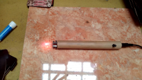
this is what i making for.
It is an pyrography soldering iron.
Unlike an ordinary solder, it is very short pin so comfortable for drawing.
The picture above is the 1st generation. the handle is getting hot and uncomfortable.
I am trying build the better one.
Basiclly, it convert 12v to 1v (or less) but have about tens ampere (my multimeter overloaded measuring the current).
I cannot use the buck converter because the diode/mosfet cannot handle the big current with low voltage.
Typically mosfet resistance is about 0.05-0.1 ohm. The resistance is not low enough.
The glowing tip is a nichrome wire, 1mm diameter, 3 cm length, 0.15 ohm.
So the best approach is using svs driver (similar to induction heater).
Lowering down the voltage by transformer's turn ratio
The primary winding of transformer is 12 turns. the secondary just 1 turn with thick wire or multiple insulated thin wire,
connected directly to the nichome wire.
When the tip detached, all 3 transformer produces very low heat,
but if the tip attached the 2 small transformers are getting very hot. The bigger one is bit hotter.
I am not sure where the heat coming from (ferrite or wire) because i dont have a thermal camera
Maybe the heat coming from ferrite.
After 10 seconds operation, i use my finger to measure the transformer's temperature.
It is unlikely from wire because wire is so thin and should get cool quickly after powering off.
Note:
the secondary wire insulated by heat resistant fiber + alumunium foil + heat resistant fibers again.
It should prevent heat transfer from the glowing tip to ferrite core by conduction and radiation.
Is that the design limit
I will try using IRF520 mosfet (gate's capacitance is 400pf but rds on is 0.27 ohm),
running with higher frequency (hoping the mosfet not getting stress),
but i am not sure it will work as expected.
any other mosfet suggestion?

The simulator just for explaning how i assembly the components,
the simulation result is different from reality.
Yunus, Mon Sept 18 2017, 06:38AM

this is what i making for.
It is an pyrography soldering iron.
Unlike an ordinary solder, it is very short pin so comfortable for drawing.
The picture above is the 1st generation. the handle is getting hot and uncomfortable.
I am trying build the better one.
Basiclly, it convert 12v to 1v (or less) but have about tens ampere (my multimeter overloaded measuring the current).
I cannot use the buck converter because the diode/mosfet cannot handle the big current with low voltage.
Typically mosfet resistance is about 0.05-0.1 ohm. The resistance is not low enough.
The glowing tip is a nichrome wire, 1mm diameter, 3 cm length, 0.15 ohm.
So the best approach is using svs driver (similar to induction heater).
Lowering down the voltage by transformer's turn ratio
The primary winding of transformer is 12 turns. the secondary just 1 turn with thick wire or multiple insulated thin wire,
connected directly to the nichome wire.
When the tip detached, all 3 transformer produces very low heat,
but if the tip attached the 2 small transformers are getting very hot. The bigger one is bit hotter.
I am not sure where the heat coming from (ferrite or wire) because i dont have a thermal camera

Maybe the heat coming from ferrite.
After 10 seconds operation, i use my finger to measure the transformer's temperature.
It is unlikely from wire because wire is so thin and should get cool quickly after powering off.
Note:
the secondary wire insulated by heat resistant fiber + alumunium foil + heat resistant fibers again.
It should prevent heat transfer from the glowing tip to ferrite core by conduction and radiation.
Is that the design limit

I will try using IRF520 mosfet (gate's capacitance is 400pf but rds on is 0.27 ohm),
running with higher frequency (hoping the mosfet not getting stress),
but i am not sure it will work as expected.
any other mosfet suggestion?
The simulator just for explaning how i assembly the components,
the simulation result is different from reality.
Re: High frequency ZVS driver with low heat waste
Yunus, Mon Sept 18 2017, 02:34PM
I think I choose the wrong ferrite ðŸ˜
There are many kinds of ferrite.
Yunus, Mon Sept 18 2017, 02:34PM
I think I choose the wrong ferrite ðŸ˜
There are many kinds of ferrite.
It is important to select the right material for the application, as the correct ferrite for a 100 kHz switching supply (high inductance, low loss, low frequency) is quite different to that for an RF transformer or ferrite rod antenna, (high frequency low loss, but lower inductance), and different again from a suppression ferrite (high loss, broadband)
https://en.m.wikipedia.org/wiki/Ferrite_core
Print this page